PrecisionLineï RCR-PET - UTCFS Global Security Products
PrecisionLineï RCR-PET - UTCFS Global Security Products
PrecisionLineï RCR-PET - UTCFS Global Security Products

You also want an ePaper? Increase the reach of your titles
YUMPU automatically turns print PDFs into web optimized ePapers that Google loves.
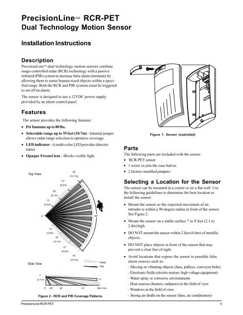
PrecisionLine <strong>RCR</strong>-<strong>PET</strong><br />
Dual Technology Motion Sensor<br />
Installation Instructions<br />
Description<br />
PrecisionLine dual technology motion sensors combine<br />
range-controlled radar (<strong>RCR</strong>) technology with a passive<br />
infrared (PIR) system to increase false alarm immunity by<br />
allowing them to sense human-sized objects within a specified<br />
range. Both the <strong>RCR</strong> and PIR systems must be triggered<br />
to set off an alarm.<br />
The sensor is designed to use a 12VDC power supply<br />
provided by an alarm control panel.<br />
Features<br />
The sensor provides the following features:<br />
• Pet Immune up to 80 lbs.<br />
• Selectable range up to 35 feet (10.7m) - Internal jumper<br />
allows radar range selection to optimize coverage.<br />
• LED indicator - A multi-color LED provides detector<br />
status.<br />
• Opaque Fresnel lens - Blocks visible light.<br />
Top View<br />
Side View<br />
0’<br />
7’<br />
(2.1m)<br />
13’<br />
(4.0m)<br />
0’<br />
PrecisionLine <strong>RCR</strong>-<strong>PET</strong><br />
20’<br />
(6.1m)<br />
13’<br />
(4.0m)<br />
20’<br />
(6.1m)<br />
27’<br />
(8.2m)<br />
35’<br />
(10.7m)<br />
27’<br />
(8.2m)<br />
35’<br />
(10.7m)<br />
60° 30° 15°<br />
90°<br />
Figure 2 - <strong>RCR</strong> and PIR Coverage Patterns<br />
Radar<br />
PIR<br />
4°<br />
floor line<br />
Figure 1. Sensor (exploded)<br />
Parts<br />
The following parts are included with the sensor:<br />
• <strong>RCR</strong>-<strong>PET</strong> sensor<br />
• 1 screw to join the case halves<br />
• 2 factory-installed jumpers<br />
Selecting a Location for the Sensor<br />
The sensor can be mounted in a corner or on a flat wall. Use<br />
the following guidelines to determine the best location to<br />
install the sensor:<br />
• Mount the sensor so the expected movement of an<br />
intruder is within a 90-degree radius in front of the sensor.<br />
See Figure 2.<br />
• Mount the sensor on a stable surface 7 to 8 feet (2.1 to<br />
2.4m) high.<br />
• DO NOT mount the sensor within 2 feet (0.6m) of metallic<br />
objects.<br />
• DO NOT place objects in front of the sensor that may<br />
prevent a clear line of sight.<br />
• Avoid locations that expose the sensor to possible false<br />
alarm sources such as:<br />
– Moving or vibrating objects (fans, pulleys, conveyor belts)<br />
– Electronic fields (electric motors, high voltage equipment)<br />
– Water spray or corrosive environments<br />
– Heat sources (heaters, radiators) in the field of view<br />
– Windows in the field of view<br />
– Strong air drafts on the sensor (fans, air conditioners)<br />
1
• When installing multiple sensors:<br />
– DO NOT mount sensors facing each other.<br />
– Mount them at least 40 feet (12.2m) apart.<br />
– Mounting sensors back to back is not recommended, but<br />
if an application requires such mounting, use the 13-foot<br />
(4.0m) range, mount at least 1foot (0.3m) apart, and walk test<br />
the installation to ensure proper operation.<br />
Flat wallmount<br />
knockout<br />
Terminal<br />
sockets<br />
Installing the Sensor<br />
All wiring must conform to the National Electric Code (NEC)<br />
and/or local codes having jurisdiction.<br />
Important: DO NOT use this device for safety interlock<br />
applications.<br />
Use the following steps to install the sensor:<br />
1. Run the security system wiring to the sensor location.<br />
2. Lift off the front cover/electronic module. Remove the<br />
nameplate and loosen the screw if necessary. See<br />
Figure 1.<br />
Cornermount<br />
knockouts<br />
Strain relief<br />
Wiring<br />
knockout<br />
Cornermount<br />
knockouts<br />
Flat wallmount<br />
knockout<br />
CAUTION<br />
You must be free of all static electricity before<br />
handling sensor circuit boards. Touch a<br />
grounded, bare metal surface before touching<br />
circuit boards or wear a grounding strap.<br />
Figure 3. Sensor Base<br />
3. If necessary, set the jumpers on the circuit board. See<br />
Setting the Jumpers.<br />
4. Remove the appropriate wiring and mounting knockouts<br />
from the back cover. The sensor can be mounted<br />
on a flat wall or in a corner. See Figure 3.<br />
5. Pull the wires through the knockout holes and use the<br />
two screws provided to attach the base to the wall. Use<br />
screw anchors if necessary.<br />
6. Strip 1/4 inch (6.4 mm) of insulation from each wire.<br />
7. Run each wire through the strain relief and under the<br />
appropriate screw terminals on the base and tighten<br />
the screws. See Figure 3.<br />
8. Line up the tabs on the bottom of the cover/electronic<br />
module with the corresponding tabs on bottom of the<br />
base and snap the cover/electronic module firmly down<br />
onto the base.<br />
9. Tighten the screw and replace the nameplate. See<br />
Figure 1.<br />
10. Apply power. The LED should light green for approximately<br />
25 seconds and then go out.<br />
11. Walk test the coverage pattern as follows:<br />
– Walk throughout the intended coverage area.<br />
J2<br />
J3<br />
J3 LED<br />
Disable<br />
– Verify the sensor alarms. See Understanding the LED.<br />
J2 Range<br />
Figure 4. Main Circuit Board<br />
2 PrecisionLine <strong>RCR</strong>-<strong>PET</strong>
Setting the Jumpers<br />
The sensor provides jumpers to select the detection range<br />
and LED operation. See Figure 4.<br />
J2 Range - Use the jumper to cover the center pin and the pin<br />
indicating the desired range. No jumper = 27 feet (8.2m) and<br />
under.<br />
35 feet (10.7m) and under 27 feet (8.2m) and under<br />
(Factory default)<br />
35’<br />
(10.7m)<br />
35’<br />
(10.7m)<br />
SB01 Swivel Mount Bracket<br />
For ceiling-mount applications that require 90 degree<br />
coverage, an optional ceiling-mount swivel bracket (SB01) is<br />
available. See Figure 5.<br />
27’<br />
(8.2m)<br />
13’<br />
(4.0m)<br />
27’<br />
(8.2m)<br />
13’<br />
(4.0m)<br />
20’<br />
(6.1m)<br />
20’<br />
(6.1m)<br />
20 feet (6.1m)and under 13 feet (4.0m) and under<br />
35’<br />
(10.7m)<br />
35’<br />
(10.7m)<br />
Figure 5. SB01 Swivel-Mount Bracket<br />
27’<br />
(8.2m)<br />
Important: You need to set J2 as close to the intended<br />
coverage range as possible. Overshooting the coverage<br />
area may cause false alarms.<br />
J3 LED -<br />
20’<br />
(6.1m)<br />
Pet Immunity<br />
13’<br />
(4.0m)<br />
27’<br />
(8.2m)<br />
ON = LED enabled (factory default)<br />
OFF = LED disabled<br />
20’<br />
(6.1m)<br />
13’<br />
(4.0m)<br />
When mounted properly, the <strong>RCR</strong>-<strong>PET</strong> sensor provides false<br />
alarm immunity to dogs and similar animals. The size and<br />
temperature of the animal, which is affected by the length of<br />
the animal’s coat, affects the immunity to false alarms. Dogs<br />
vary in body temperature by breed, a very warm-blooded dog<br />
with short hair will not be as immune to false alarms as a<br />
similar sized dog with long hair. Therefore, the acceptable<br />
short hair dog is limited to a smaller (lighter) weight dog. See<br />
the examples listed in the following table:<br />
Maintaining the Sensor<br />
When installed and used properly, the sensor provides<br />
years of service with minimal maintenance. You should walk<br />
test the sensor annually to ensure proper operation.<br />
Understanding the LED<br />
The multi-color LED located on the bottom of the sensor<br />
indicates the status of the unit as described in the following<br />
table.<br />
LED<br />
Red<br />
Green<br />
Yellow<br />
Status<br />
PIR and <strong>RCR</strong> detection. The sensor is in<br />
alarm and the relay has switched.<br />
PIR detection only (no alarm).<br />
<strong>RCR</strong> detection only (no alarm).<br />
After 30 minutes the LED will only indicate an alarm condition.<br />
Drop power to reset the walktest timer.<br />
Long hair<br />
(2" long) up<br />
to 80 lbs.<br />
Medium hair<br />
(1.5" long)<br />
up to 50 lbs.<br />
Short hair<br />
(1" long) up to<br />
30 lbs.<br />
Not recommended<br />
Use pet alley<br />
application<br />
Chinook<br />
Collie<br />
Basenji<br />
Doberman<br />
Husky<br />
English<br />
Setter<br />
Border<br />
Terrier<br />
Great Dane<br />
Poodle<br />
Pointer<br />
Cocker<br />
Spaniel<br />
Greyhound<br />
Retriever<br />
Pug<br />
French<br />
Bulldog<br />
Mastiff<br />
Sheepdog<br />
Toy<br />
Poodle<br />
Mini<br />
Bull Terrier<br />
Pit Bull<br />
Shepherd<br />
Weimeraner<br />
Welsh<br />
Corgi<br />
St. Bernard<br />
Cats<br />
PrecisionLine <strong>RCR</strong>-<strong>PET</strong><br />
3
FCC Compliance<br />
This device complies with Part 15 of the FCC rules.<br />
Operation is subject to the following two conditions:<br />
(1) This device may not cause harmful interference.<br />
(2) This device must accept any interference received,including<br />
interference that may cause undesired operation.<br />
FCC ID: CGGAA2<br />
Specifications<br />
Input voltage<br />
8.5 to 18VDC<br />
Typical current 20mA<br />
Maximum current 27mA<br />
Electrical configuration Form A<br />
Relay rating<br />
40VDC, 300mA max.,<br />
6W Load max.<br />
Detection range 35' (10.7m) x 90°<br />
Target velocity 0.5 ft/sec to 5 ft/sec<br />
Alarm duration 5 sec. ± 10%<br />
Mounting height 7' to 8' (2.1m to 2.4m)<br />
Operating temperature 32°F to 122°F (0°C to 50°C)<br />
Relative humidity 5 to 93% non-condensing<br />
Dimensions<br />
Width 2.8" (71mm)<br />
Height 5.1" (130mm)<br />
Depth 2.3" (58mm)<br />
Weight<br />
6 oz (170g)<br />
Color<br />
White<br />
Field wiring size 12-24 AWG<br />
Product Ordering<br />
Model Number<br />
<strong>RCR</strong>-<strong>PET</strong><br />
Accessories<br />
SB01<br />
Description<br />
PrecisionLine Dual Technology Motion Sensor with Pet Immunity up to 80 lbs., Form A<br />
Swivel-Mount Bracket<br />
g<br />
GE <strong>Security</strong><br />
www.ge-security.com<br />
1037946 Rev D 03/10