Repro Rev-D Owners Manual - RTZ Professional Audio
Repro Rev-D Owners Manual - RTZ Professional Audio
Repro Rev-D Owners Manual - RTZ Professional Audio

Create successful ePaper yourself
Turn your PDF publications into a flip-book with our unique Google optimized e-Paper software.
<strong>Repro</strong>duce Amplifier<br />
<strong>Rev</strong>ision-D<br />
AMPEX UPGRADE ELECTRONICS<br />
<strong>Owners</strong> <strong>Manual</strong><br />
<strong>RTZ</strong> <strong>Professional</strong> <strong>Audio</strong><br />
4260 Pine Vista Blvd<br />
Alpharetta, GA 30022 USA<br />
Web: http://www.rtzaudio.com<br />
Email: rtzaudio@mindspring.com<br />
COPYRIGHT © 2003-2005, <strong>RTZ</strong> AUDIO<br />
DOC-REV-A5<br />
02/18/2005
<strong>Repro</strong>duce <strong>Rev</strong>-D<br />
1. INTRODUCTION<br />
Thank you for purchasing your new <strong>RTZ</strong><br />
upgrade electronics for Ampex studio recorders!<br />
All of our cards are hand built and individually<br />
tested prior to shipping. Before installing any<br />
cards, please read this document thoroughly<br />
and retain it for future reference. Additional<br />
copies of this manual are available upon request<br />
or may be downloaded from our website at<br />
http://www.rtzaudio.com.<br />
All items are carefully packed to endure the<br />
rigors of shipping and handling. However,<br />
please inspect all contents and packaging<br />
immediately upon receipt. Please report any<br />
problems to us immediately. In the event of<br />
damage, retain all shipping and packaging<br />
materials for shipper damage claims inspection.<br />
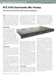
2. DESCRIPTION<br />
The <strong>Rev</strong>-D reproduce cards are modern<br />
replacement electronics designed to greatly<br />
enhance the playback performance of vintage<br />
Ampex 440/1100/1200 series studio recorders.<br />
The original Ampex head amplifier design has<br />
been combined with a new modern head input<br />
transformer. The line amplifier stage has been<br />
completely redesigned to provide improved<br />
specifications and sonic performance. The<br />
PCB’s are full ground plane types for improved<br />
shielding and circuit stability. An onboard<br />
thermal poly fuse protects the PCB and<br />
components against further damage in the event<br />
of a short or component failure.<br />
Originally, Ampex made a number of minor<br />
circuit design and component changes during<br />
the evolution of the various machines supported<br />
by the <strong>Rev</strong>-D reproduce cards. As such, our<br />
cards are populated with the appropriate<br />
components upon ordering for the machine type<br />
specified. In some cases the reproduce cards<br />
may interchange between different series<br />
recorders with only EQ realignment and/or<br />
jumper changes required. In other cases, a few<br />
component values may need to be changed,<br />
added or removed to achieve proper alignment.<br />
Please refer to the schematic for additional<br />
information on component values and changes.<br />
In general, this document covers details specific<br />
to the <strong>RTZ</strong> <strong>Rev</strong>-D reproduce cards. Otherwise,<br />
you should perform the alignment procedures as<br />
originally specified in the Ampex Operation and<br />
Maintenance manual supplied with the machine.<br />
If you experience any difficulty installing or<br />
aligning the electronics, please contact us<br />
directly for assistance.<br />
3. HEAD INPUT TRANSFORMER<br />
CONFIGURATION<br />
The input transformer must be configured to<br />
match the head impedance of the recorder being<br />
upgraded. Jumper block JP1 selects the head<br />
input transformer ratio for either 1:4 or 1:8 turns<br />
ratio. The jumper configuration also depends on<br />
whether the head resonance trimmer (VR2) is<br />
installed. In either case, you may want to<br />
experiment between ratios and note the<br />
record/playback response during testing. The<br />
goal is to obtain the best matching between the<br />
playback head and head input transformer for<br />
both tape speeds.<br />
Note that the MM-1200 typically requires 1:8<br />
turns ratio with the head resonance trimmer VR2<br />
installed. Otherwise, the 1:4 ratio should be<br />
used with FET switch Q13 installed and no VR2<br />
resonance trimmer for the MM1200. The AG440<br />
series recorders usually require a 1:8 turns ratio<br />
for proper alignment. Refer to Table 1 for the<br />
jumper options. Confirm the JP1 jumper settings<br />
from the table below before installing the new<br />
cards.<br />
Table 1<br />
Ratio JP1 Jumpers Usage<br />
1:4 1 & 2 LOW-Z<br />
1:8 3 & 4 HIGH-Z<br />
It is extremely important that the recorder heads<br />
are in good condition to obtain optimum<br />
alignment and frequency response. Worn or<br />
damaged heads will make optimum alignment<br />
difficult and/or impossible. Likewise it is<br />
extremely helpful to plot the current frequency<br />
response of the recorder using the stock<br />
electronics with a calibrated test tape (we<br />
recommend MRL alignment tapes) before<br />
making any upgrades. In other words, you want<br />
to know what the frequency response of the<br />
machine is prior to upgrade for comparison<br />
purposes later. The original frequency response<br />
information will be needed if you encounter<br />
alignment difficulties after upgrading!<br />
<strong>RTZ</strong> <strong>Professional</strong> <strong>Audio</strong> 1
<strong>Repro</strong>duce <strong>Rev</strong>-D<br />
N O T E<br />
MAKE SURE YOUR RECORDER’S HEADS ARE IN<br />
PROPER CONDITION BEFORE UPGRADING. WE<br />
RECOMMEND SENDING THE HEADSTACK TO JRF<br />
MAGNETICS FOR EVALUATION PRIOR TO MAKING ANY<br />
CHANGES IF THE HEADSTACK IS OF UNKNOWN<br />
CONDITION!<br />
4. EQUALIZER CONFIGURATION<br />
The <strong>RTZ</strong> <strong>Rev</strong>-D cards include a universal EQ<br />
daughter card that is jumper configurable for any<br />
of the equalizations and tape speeds originally<br />
supported by the stock Ampex recorders. This<br />
includes speed ranges from 3-3/4 through 30<br />
IPS for the NAB or CCIR equalization standards.<br />
The original Ampex 4020270-01, 4020270-02 or<br />
4020270-03 EQ option types may be selected<br />
via jumpers JP1 and JP2. Optional speed<br />
indicator LED’s may also be installed on the<br />
card for diagnostic purposes as well. The LED’s<br />
may be enabled or disabled via jumper 4 on<br />
JP4. Refer to the schematic or Table 2 for the<br />
EQ configuration options available.<br />
Note that the <strong>RTZ</strong> 4020270-D equalizer cards<br />
are direct replacements for standard Ampex<br />
equalizer cards used in the AG-440, MM-1000,<br />
MM-1100, and MM-1200 series studio recorders<br />
with the appropriate jumper settings configured.<br />
Thus, the reproduce EQ cards may be swapped<br />
between the original Ampex cards or <strong>RTZ</strong> cards<br />
if needed.<br />
Before installing your new <strong>RTZ</strong> cards, verify that<br />
the correct EQ jumper settings are set from<br />
Table 2 according to the machine and tape<br />
speed required. Note that the speed select<br />
indicator LED’s are generally not installed or<br />
enabled on multi-track recorders to avoid<br />
excessive current drain on the power supply and<br />
EQ switching driver transistors. However, you<br />
may wish to install LED’s on a couple of cards<br />
for diagnostics purposes if desired.<br />
Table 2<br />
Original Ampex EQ Card P/N JP1 JP2<br />
4020270-01 (3¾ - 15ips NAB or CCIR) 2 & 4 1<br />
4020270-02 (7½ - 15ips NAB or CCIR) 1 & 3 1<br />
4020270-03 (15 - 30ips NAB or CCIR) 1 & 3 1 & 2<br />
JP1<br />
EQ Range Select<br />
JP2<br />
EQ Type Select<br />
<strong>RTZ</strong> <strong>Professional</strong> <strong>Audio</strong> 2
<strong>Repro</strong>duce <strong>Rev</strong>-D<br />
5. INSTALLING THE NEW CARDS<br />
Many of the components on the repro cards<br />
have HOT +39V supply voltage directly<br />
exposed. This includes the metal transistors<br />
cases and the heat sink. Any contact of the heat<br />
sink or metal transistor bodies, to ground or<br />
other signal sources, will most likely cause<br />
immediate damage to the card components.<br />
Always use extreme care when handling or<br />
working around the repro cards during testing<br />
and alignment to avoid damage.<br />
In the event of component damage or a short,<br />
thermal poly fuse MF1 will heat rapidly at around<br />
200ma current and revert to high impedance<br />
open circuit state. The fuse remains heated and<br />
open as long as the over-current condition<br />
persists. If the card fails to operate and the fuse<br />
is hot to the touch, do not attempt to continue<br />
operating the card. This indicates a shorted<br />
component condition that requires repair. If card<br />
damage occurs, please contact <strong>RTZ</strong> directly or a<br />
qualified service person for repairs.<br />
C A U T I O N<br />
SOME RECORDERS (I.E THE AG-440) HAVE AN<br />
INTERNAL CARD CHASSIS SHIELD IN THE SLOT NEAR<br />
THE REAR EDGE CONNECTOR. MAKE SURE THE<br />
REPRO CARD HEATSINK DOES NOT CONTACT THIS<br />
WHEN INSERTED BEFORE POWERING UP THE<br />
MACHINE! IF NEEDED, BEND THE SHIELD OVER<br />
SLIGHTLY BY HAND TO AVOID ANY POSSIBLE<br />
CONTACT WITH THE HEATSINK WHEN THE CARD IS<br />
INSERTED INTO THE SLOT!<br />
6. ALIGNMENT PROCEDURES<br />
After the head input transformer ratio and EQ<br />
select jumpers are properly configured, align<br />
and bias the recorder using the normal<br />
reproduce and record alignment procedures.<br />
Refer to the original Ampex Operation and<br />
Maintenance manual alignment section for<br />
complete details.<br />
You will notice the reproduce calibration level<br />
drops by about 5 – 7 dB after installing the <strong>RTZ</strong><br />
cards – this is normal. Adjust the reproduce<br />
calibration level to make up this difference. The<br />
gain structure of the <strong>RTZ</strong> cards is designed for<br />
high output tape levels. This design helps<br />
recover some of the lost headroom associated<br />
with using stock cards with modern high output<br />
tape formulations.<br />
We strongly recommend making notes of the<br />
record and reproduce response of the recorder<br />
with the original cards before installing the new<br />
cards. This will provide a known response for<br />
comparison purposes after installing the new<br />
cards. As with any major component changes, it<br />
is advisable to change one card initially. If<br />
possible, make sure the tape recorder is in (or at<br />
least close to) proper alignment, including head<br />
alignment, before installing any new cards.<br />
During initial alignment, start incrementally with<br />
one channel (or group of channels for multi-track<br />
recorders) and perform the complete reproduce<br />
and record alignment procedures as outlined in<br />
the Ampex manual. Be sure to compare<br />
frequency response notes against the original<br />
cards. In general, you should pay particular<br />
attention to the HF frequency response during<br />
RECORD ALIGNMENT (particularly at 10 KHZ<br />
and above 16 KHZ). If excessive HF rise occurs<br />
or you are unable to obtain fairly flat frequency<br />
response in the HF range, you will need to try<br />
swapping the input transformer ratio jumpers<br />
and note the results after repeating all alignment<br />
procedures.<br />
Also, you should notice extended high frequency<br />
response while performing the record alignment<br />
procedures. You may need to reduce the record<br />
high frequency EQ boost (due to improved<br />
reproduce EQ frequency response). In most<br />
cases, the new precision cards and components<br />
provide significant improvements over the<br />
original design cards.<br />
7. HEAD RESONANCE ADJUSTMENT<br />
Later generations of the AG-440C recorders<br />
electronics included a head resonance<br />
adjustment trimmer. The <strong>Rev</strong>-D cards also<br />
support head resonance adjustment if trimmer<br />
VR2 is installed. The resonance adjustment<br />
trimmer was only available in later issues as far<br />
as we know. Some of the later issues of the 440<br />
and 1200 series recorders were equipped with<br />
this option also.<br />
Note the head resonance trimmer adjustment<br />
procedure requires a repro extender card. If you<br />
do not have access to an extender card, trimmer<br />
VR2 should be adjusted counter clockwise<br />
(CCW) for 18 or more turns to disable. The<br />
<strong>RTZ</strong> <strong>Professional</strong> <strong>Audio</strong> 3
<strong>Repro</strong>duce <strong>Rev</strong>-D<br />
trimmer clicks when adjusted past either end<br />
stop. Note that the reproduce high frequency<br />
equalization response is associated with the<br />
resonance trimmer and the EQ HF trimmers for<br />
each speed. The resonance trimmer adjustment<br />
is a one-time procedure that affects both<br />
speeds. When turned clockwise VR2 raises the<br />
resonant frequency and reduces the gap loss<br />
compensation.<br />
During record alignment (while monitoring on<br />
playback) the resonance trimmer should be<br />
adjusted while sweeping the recorder from<br />
between 15-25 kHz. Typically the HF response<br />
will tend to rise above 15 kHz due to resonance.<br />
Adjust the resonance trimmer clockwise (CW) to<br />
raise the resonance point. As the resonance<br />
point is raised, the HF response should flatten<br />
out when the peak resonance point is moved<br />
higher in frequency.<br />
Note that if the resonance trimmer is adjusted to<br />
extreme CW position, the 1-10 kHz frequency<br />
response will begin to degrade and alignment<br />
will not be possible. On some machines, such as<br />
the MM1200, the circuit may begin to<br />
“motorboat” or oscillate if adjusted to the<br />
extreme. Therefore, the resonance trimmer must<br />
be adjusted during the HF record/playback<br />
alignment and proper response is obtained over<br />
the entire frequency range.<br />
8. RECORDER ALIGNMENT AND<br />
CONFIGURATION TIPS<br />
As previously mentioned, the HF response must<br />
be verified during record and playback to obtain<br />
optimum HF response. The 1 kHz and 10 kHz<br />
alignment tape test tones will typically align<br />
easily. However, the frequency response above<br />
15 kHz requires tweaking to obtain optimum<br />
results. The HF frequency response is directly<br />
affected by the resonance of the head input<br />
transformer and playback head.<br />
Head resonance adjustments are facilitated by<br />
trimmer VR2 or by using a damping resistor<br />
installed at R11. FET switch Q13 (J174) is<br />
provided to enable head damping resistor R11<br />
at high tape speed only if desired. Normally this<br />
build configuration is used on the MM-1200 if no<br />
resonance trimmer is installed and the head<br />
input transformer ratio is configured for 1:4. If a<br />
damping resistor is required at both speeds,<br />
Q13 may be omitted and the D (drain) and S<br />
(source) pads should be jumpered. In this<br />
configuration, the optimum value of the damping<br />
resistor will depend on the recorders playback<br />
head. We suggest installing temporary lead<br />
wires to an external 100K potentiometer to<br />
determine the best value for R11 during record<br />
alignment. We’ve found 22.1K to be the best<br />
value for our MM-1200 when the resonance<br />
trimmer is not used.<br />
We’ve discovered that the input transformer ratio<br />
of 1:8 must be used on the MM-1200 at 15/30<br />
IPS if the resonance adjustment trimmer is<br />
installed. Using GP-9 tape over-biased at 3.00<br />
db, we were able to obtain flat response to well<br />
above 20 kHz at 15 IPS. The 30 IPS response<br />
tended to have a slight, but acceptable, rise<br />
above 20 kHz. When the resonance trimmer is<br />
properly adjusted, both tape speeds should<br />
show significant improvements in HF frequency<br />
response. Improper or over adjustment will<br />
affect the entire frequency response and<br />
possibly cause the circuit to oscillate or<br />
“motorboat”. A fixed damping resistor value<br />
(Q13 source and drain pads jumpered) of 20-<br />
50k may also be required to prevent any<br />
oscillation.<br />
On the AG-440 the 1:8 ratio will generally yield<br />
the best results. In some cases, depending on<br />
tape speed used, the 1:4 ratio may give better<br />
results. Our lab machine is a 440-C configured<br />
for 15-30 IPS NAB using the 1:8 ratio.<br />
Therefore, it is typically best to start with 1:8<br />
turns ratio on the 440 machines. With proper<br />
adjustment you should notice significant<br />
improvement in the overall frequency response<br />
of the recorder.<br />
The reproduce equalizer card JP3 jumper<br />
position #2 enables an additional low frequency<br />
smoothing network for high-speed. Typically,<br />
this option was used on the MM-1200 to smooth<br />
the LF response around the 100 Hz and below<br />
region. The low-frequency EQ trimmer will have<br />
less effect if the jumper is installed in position<br />
#2. If you are unable to obtain acceptable LF<br />
response adjustment during alignment, remove<br />
the jumper at position #2 from JP3 on the<br />
equalizer card.<br />
<strong>RTZ</strong> <strong>Professional</strong> <strong>Audio</strong> 4
<strong>Repro</strong>duce <strong>Rev</strong>-D<br />
Line Amplifier Specifications<br />
The following specifications are for the line amplifier stage only. Max level is about +23 dbu, direct and<br />
about +27 dbu via transformer at 39 VDC. Data is shown for the <strong>RTZ</strong> and stock cards for comparison<br />
purposes.<br />
Noise Measurements:<br />
RMS measurement with input "OFF" (grounded).<br />
A-Weighted <strong>RTZ</strong> Ampex<br />
22Hz/22kHz -88 dbu -75 dbu<br />
22Hz/80 kHz -88 dbu -75 dbu<br />
Basic THD+N:<br />
No transformer @ +4dbu into 150 Ohm Load or no load (100k):<br />
<strong>RTZ</strong><br />
Ampex<br />
Frequency 150 Ohm 100k load 150 Ohm 100k load<br />
load<br />
load<br />
1 kHz 0.0029% 0.00290% 0.0151% 0.0067%<br />
10 kHz 0.0056% 0.00522% 0.0269% 0.0252%<br />
100 Hz 0.00384% 0.00282% 0.0108% 0.0135%<br />
20 Hz 0.00289% 0.00281% 0.053% 0.031%<br />
<strong>RTZ</strong> <strong>Professional</strong> <strong>Audio</strong> 5