900 MHz Integrated STHT Homer Autotuner Datasheet - S-TEAM Lab
900 MHz Integrated STHT Homer Autotuner Datasheet - S-TEAM Lab
900 MHz Integrated STHT Homer Autotuner Datasheet - S-TEAM Lab

You also want an ePaper? Increase the reach of your titles
YUMPU automatically turns print PDFs into web optimized ePapers that Google loves.
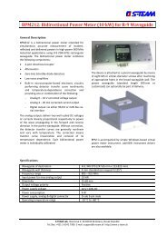
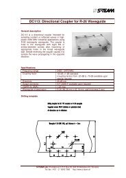
STOLPA: <strong>Integrated</strong> R-9 Waveguide <strong>Autotuner</strong><br />
Basic Description<br />
The HOMER-Series <strong>STHT</strong> <strong>900</strong>-<strong>MHz</strong> <strong>Autotuner</strong> (aliased<br />
STOLPA in memory of Ing. Milivoj Štolpa, who greatly<br />
assisted in applications of six-port reflectometers in<br />
former Czechoslovakia) integrates HOMER Analyzer<br />
(automatic impedance and power measurement system)<br />
and HOMER Mototuner (a three-stub motorized<br />
tuner) in one compact unit. Based on R-9 (WR-975)<br />
waveguide, the system works under the full-power operating<br />
conditions of magnetron-based microwave generators.<br />
The Analyzer part measures both magnitude<br />
and phase of reflection coefficient as well as incident,<br />
reflected and absorbed power and frequency. The Mototuner<br />
consists of three stepping-motor-driven tuning<br />
stubs spaced in mutual distances of nominally one quarter<br />
of guide wavelength. The tuner uses data measured<br />
by Analyzer for fast automatic impedance matching of<br />
time-varying loads in all industrial applications, including<br />
plasma. The system is designed for CW, high-ripple<br />
(Rectified) and Pulsed operation modes. <strong>STHT</strong> can be:<br />
<br />
Used autonomously without external controller;<br />
<br />
<br />
Controlled from a personal computer via RS232 or<br />
CAN interface;<br />
<strong>Integrated</strong> into a <strong>Lab</strong>VIEW environment;<br />
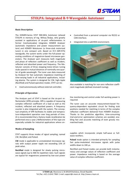
Also available is matching for non-zero reflection coefficient<br />
magnitude (defined mismatch tuning).<br />
Principle of Operation<br />
The Analyzer part of <strong>STHT</strong> is based on the six-port reflectometer<br />
(SPR) principle. SPR is capable of measuring<br />
complex reflection coefficient of a load as well as the<br />
incident, reflected and absorbed powers. A frequency<br />
counter is also integrated with the system. The conceptual<br />
simplicity of SPR facilitates its stable and temperature-independent<br />
operation over long periods of time.<br />
(It is recommended that a factory-made recalibration be<br />
performed once a year.) Reflectometers of this type are<br />
especially suitable for industrial applications where online<br />
monitoring and control under full working power is<br />
required.<br />
The tuner uses an accurate measurement-based frequency-dependent<br />
equivalent circuit for finding stub<br />
positions needed for matching in terms of the complex<br />
reflection coefficient delivered from HOMER Analyzer.<br />
Thanks to the predictive algorithm, time-consuming<br />
trial-and-error optimization schemes are avoided, enabling<br />
fast and accurate matching of even grossly mismatched<br />
loads.<br />
Modes of Sampling<br />
<strong>STHT</strong> supports three modes of signal sampling, named<br />
CW, Rectified, and Pulsed.<br />
CW mode is applicable to unmodulated microwave signals<br />
with output power ripple not exceeding 15% of<br />
peak value.<br />
Rectified mode is designed for slowly pulsing microwave<br />
signals (up to 400 Hz repetition rate). Such signals<br />
are typical for magnetrons powered by low-cost power<br />
supplies which incorporate simple half-wave or fullwave<br />
rectifiers.<br />
Pulsed mode option is intended primarily for sampling<br />
fast pulse-modulated microwave signals with pulse<br />
widths down to 100 s.<br />
Rectified and Pulsed modes can provide both instantaneous<br />
and average values of reflection coefficient and<br />
power. Impedance matching is based on the average<br />
value of complex reflection coefficient.<br />
S-<strong>TEAM</strong> <strong>Lab</strong>, Ilkovicova 3, SK-84104 Bratislava, Slovak Republic<br />
Tel./fax: +421-2-6542 7968 E-mail: support@s-team.sk http://www.s-team.sk
<strong>STHT</strong> <strong>900</strong> <strong>MHz</strong><br />
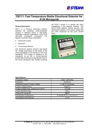
HomSoft Windows Control, Visualization and Data Logging Software<br />
Although designed as a stand-alone system, the<br />
HomSoft control, visualization and data logging software<br />
significantly expands the system capabilities. The basic<br />
HomSoft features include:<br />
<br />
Microsoft Windows® environment<br />
Accurate measurement of complex reflection<br />
coefficient and its displaying in various formats,<br />
including<br />
- Magnitude<br />
- Phase<br />
- Return Loss<br />
- VSWR<br />
- Polar Display<br />
- Smith Charts (Z and Y)<br />
- Rieke-Type Chart<br />
<br />
Measurement of incident, reflected, and absorbed<br />
power and its displaying in various formats,<br />
including watts, decibels, percentage of incident<br />
power<br />
Numerical readout of signal frequency, load<br />
reflection coefficient and power in various formats<br />
<br />
<br />
<br />
Arbitrary shifting of the measurement plane<br />
Saving measured data as tables (text files) or<br />
pictures (BMP, GIF, JPG)<br />
Periodic data logging of all or some of the<br />
measured quantities<br />
Multiple windows enabling simultaneous<br />
observation of various quantities in different<br />
formats<br />
<br />
<br />
<br />
<br />
<br />
<br />
Wide selection of appearances of displayed curves<br />
Storing and retrieving of complete system settings<br />
tailored to particular tasks<br />
Graphical interface for tuner control (manual stub<br />
movement, step-by-step/continuous autotuning)<br />
Prescribed scenario of tuning stub movements<br />
DDE server option enables another Windows<br />
application to share measurement results<br />
Extensive on-line help<br />
REV B1. Data subject to change. 2/7 30-Jul-2013
<strong>STHT</strong> <strong>900</strong> <strong>MHz</strong><br />
Specifications<br />
Electrical<br />
Waveguide type<br />
R-9 (WR-975)<br />
Flange type<br />
IEC<br />
Frequency range 1<br />
890 ÷ 930 <strong>MHz</strong><br />
Maximum working power 2 3<br />
100 kW<br />
Minimum working power<br />
10 W<br />
Dynamic range of working power<br />
20 dB<br />
Reflection coefficient measurement error (uncertainty circle radius) 0.05<br />
Incident power measurement error (matched load) 5 %<br />
Power supply voltage<br />
24 V 10% DC<br />
Peak current consumption (all stubs moving)<br />
5 A<br />
Current consumption (stubs resting)<br />
2 A<br />
Interface<br />
RS232 or RS422, CAN Bus<br />
Modes of sampling<br />
CW, Rectified, Pulsed<br />
Max ripple in CW mode<br />
15 % of peak value<br />
Max repetition rate of signal envelope in Rectified mode 4<br />
400 Hz<br />
Min pulse width in Pulsed mode<br />
100 s<br />
Tuner<br />
Max tuning stub travel<br />
70 mm<br />
Tuning range 5 VSWR < 10:1<br />
Tuning accuracy (reflected-to-incident power ratio) 1 %<br />
Full stub insertion travel time<br />
0.55 s (high speed motors)<br />
2.5 s (standard speed motors – option)<br />
Time to achieve match<br />
Depends on load mismatch, initial stub<br />
positions and signal quality 6<br />
(continued…)<br />
1<br />
2<br />
3<br />
4<br />
5<br />
6<br />
The system can be calibratred in the three ISM sub-bands, centered at 896 <strong>MHz</strong>, 915 <strong>MHz</strong>, and 922 <strong>MHz</strong>.<br />
Actual maximum working power is fixed according to customer’s demand (must not exceed 100 kW). The actual minimum<br />
working power is 20 dB (=dynamic range) below the actual maximum operating power or 10 W, whichever is greater.<br />
Maximum working power is specified for matched load conditions. For loads with high reflection coefficient magnitude (>0.9),<br />
the maximum power is derated to avoid arcing with deeply inserted tuning stubs. Please contact the manufacturer for details.<br />
In Rectified and Pulsed modes, maximum power means peak power (not its mean value).<br />
Signal envelope repetition rate (ripple period) f e is determined by power line frequency f p and the rectification method. Examples:<br />
Half-wave-rectified signal f e =f p ; full-wave-rectified signal f e =2f p ; 3-phase ripple period f e =3f p (half-wave rectification), f e =6f p<br />
(full-wave rectification).<br />
Generally, the match will be improved for loads outside of the tuning range.<br />
For tuning speed details, see S-<strong>TEAM</strong> Application Note AN-0901.<br />
REV B1. Data subject to change. 3/7 30-Jul-2013
<strong>STHT</strong> <strong>900</strong> <strong>MHz</strong><br />
Specifications – Continued<br />
Mechanical<br />
Mass<br />
26.5 kg<br />
Length<br />
655.3 mm<br />
Width<br />
336.6 mm<br />
Height<br />
371.6 mm<br />
Surface finish E-CLPS 4600<br />
Other<br />
Cooling water flow rate (minimum)<br />
5 liters/minute<br />
Cooling water temperature 7<br />
+15 to +25 0 C<br />
Pressure drop at min water flow rate<br />
< 50 kPa<br />
Maximum working pressure<br />
500 kPa<br />
Water inlet/outlet connector 8<br />
SMC KPH12-03<br />
Water hose<br />
SMC TU 1208 Polyurethane<br />
Operating temperature range<br />
+5 to +55 0 C<br />
Storage temperature range<br />
-10 to +125 0 C<br />
7<br />
8<br />
Increase minimum cooling water temperature in condensing situation (may occur e.g. when cooling while HOMER is switched<br />
off).<br />
See e.g. www.smc.eu<br />
REV B1. Data subject to change. 4/7 30-Jul-2013
<strong>STHT</strong> <strong>900</strong> <strong>MHz</strong><br />
Configurations<br />
Basic Configuration<br />
<br />
<br />
<br />
<br />
<br />
<strong>STHT</strong> + Internal firmware (Server)<br />
Calibration in 896, 915 or 922 <strong>MHz</strong> band<br />
RS232 or RS422 serial interface<br />
CW and Rectified modes of operation<br />
Operating handbook (pdf)<br />
Communication protocol manual (pdf)<br />
Set of standard cables 9<br />
Options<br />
1. HomSoft Windows visualization and control software<br />
2. Pulsed mode of sampling<br />
3. Defined mismatch tuning<br />
4. Additional Server – CAN Bus (includes CAN Bus cable)<br />
5. CAN-USB Adapter (to connect PC to CAN Bus network)<br />
6. <strong>Lab</strong>VIEW HOMER Virtual Instruments Library<br />
7. Dynamic Data Exchange (DDE) server in HomSoft Windows SW 10<br />
8. Technical support in hours (four hours are complimentary)<br />
9. Full band calibration (890 – 930 <strong>MHz</strong>)<br />
10. Additional frequency band calibration<br />
11. Precalibration in one additional band<br />
12. Precalibration in two additional bands<br />
Optional Power Supplies<br />
- Traco Power TBL 150-124, 24V/6.25A, DIN rail mountable<br />
- Electro-Automatik EA-PS-524-11T, 24V/10.5A, input 90-264 V, benchtop<br />
9<br />
10<br />
Set of standard cables includes DC power supply cable, RS232/RS422 cable, and, in case of CAN Bus, CAN Bus cable.<br />
HomSoft Windows visualization and control SW option required.<br />
REV B1. Data subject to change. 5/7 30-Jul-2013
<strong>STHT</strong> <strong>900</strong> <strong>MHz</strong><br />
Miscellaneous<br />
Defined Mismatch Tuning. Some installations (notably some plasma applicators) may work better when the result of<br />
autotuning is not a zero reflection coefficient but a slight mismatch. Defined Mismatch Tuning option enables such<br />
tuning method, resulting in a reflection coefficient that has a user-specified, nonzero magnitude. Phase is arbitrary.<br />
CAN-USB Adapter. To connect your PC with a CAN Bus network (or with the <strong>STHT</strong> alone), the Sontheim CAN USB Light<br />
Dongle adapter is needed. You can order it as an option. Another possibility is to buy the dongle yourself from the<br />
manufacturer (see http://www.s-i-e.de ).<br />
<strong>Lab</strong>VIEW HOMER Virtual Instruments Library enables HOMER control and monitoring (measurement results retrieval)<br />
from within the National Instruments’ <strong>Lab</strong>VIEW environment. The library consists of a number of virtual subinstruments<br />
and is accompanied by a few useful examples. The library enables users to integrate HOMER into their own<br />
applications with much less effort than trying to start from scratch by studying HOMER communication protocol and<br />
programming the communication themselves.<br />
DDE Server. DDE Server is a functionality within the HomSoft Windows SW hence it needs the HomSoft Windows visualization<br />
and control software option, too. The DDE Server enables another (customer’s) Windows program to extract<br />
measurement results from HomSoft program, e.g. to a <strong>Lab</strong>VIEW environment.<br />
Technical support. Very often users, especially in the initial phase, need counsel about issues that are not the matter<br />
of HOMER itself but of their particular application, or about topics that are in detail described in the accompanying<br />
documentation. Four hours of such support are provided free of charge; additional support should be ordered.<br />
Full band calibration. With full band calibration, you can use <strong>Homer</strong> in any of the three ISM bands without ever be<br />
concerned with the expensive additional frequency band calibration.<br />
Additional frequency band calibration. From HW point of view, the unit is sufficiently broadband to operate at all<br />
three sub-bands without any modification. However, it has to be calibrated in each of the sub-bands. HOMER must be<br />
sent back to the manufacturer for additional frequency band calibration.<br />
Precalibration. If you plan to use more frequency bands in future but you are not sure at the time of placing the order<br />
you may opt for a precalibration in additional band(s). Precalibration means taking all the necessary data while the<br />
HOMER is installed in the calibration setup without their further processing. If you choose to extend the calibration<br />
anytime later, you will pay only the diference between full calibration and precalibration. Another advantge is that<br />
you do not have to send the unit back to the manufacturer.<br />
REV B1. Data subject to change. 6/7 30-Jul-2013
<strong>STHT</strong> <strong>900</strong> <strong>MHz</strong><br />
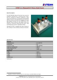
Basic Dimensions (in millimeters)<br />
655.3<br />
336.6<br />
371.6<br />
REV B1. Data subject to change. 7/7 30-Jul-2013