2.45 GHz STH 8/26 Coaxial Homer Analyzer Datasheet - S-TEAM Lab
2.45 GHz STH 8/26 Coaxial Homer Analyzer Datasheet - S-TEAM Lab
2.45 GHz STH 8/26 Coaxial Homer Analyzer Datasheet - S-TEAM Lab
- No tags were found...

You also want an ePaper? Increase the reach of your titles
YUMPU automatically turns print PDFs into web optimized ePapers that Google loves.
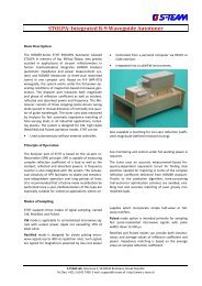
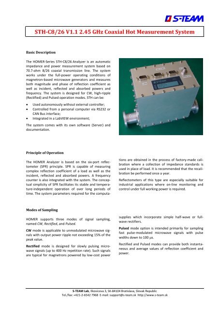
<strong>STH</strong>-C8/<strong>26</strong> V1.1 <strong>2.45</strong> <strong>GHz</strong> <strong>Coaxial</strong> Hot Measurement SystemBasic DescriptionThe HOMER-Series <strong>STH</strong>-C8/<strong>26</strong> <strong>Analyzer</strong> is an automaticimpedance and power measurement system based on70.7-ohm 8/<strong>26</strong> coaxial transmission line. The systemworks under the full-power operating conditions ofmagnetron-based microwave generators and measuresboth magnitude and phase of reflection coefficient aswell as incident, reflected and absorbed powers andfrequency. The system is designed for CW, high-ripple(Rectified) and Pulsed operation modes. <strong>STH</strong> can be:Used autonomously without external controller;Controlled from a personal computer via RS232 orCAN Bus interface;Integrated in a <strong>Lab</strong>VIEW environment;The system comes with its own software (Server) anddocumentation.Principle of OperationThe HOMER <strong>Analyzer</strong> is based on the six-port reflectometer(SPR) principle. SPR is capable of measuringcomplex reflection coefficient of a load as well as theincident, reflected and absorbed powers. A frequencycounter is also integrated with the system. The conceptualsimplicity of SPR facilitates its stable and temperature-independentoperation of over long periods oftime. The system parameters required for the computationsare obtained in the process of factory-made calibrationwhere a collection of impedance standards isused in place of load. It is recommended that the recalibrationbe performed once a year.Reflectometers of this type are especially suitable forindustrial applications where on-line monitoring andcontrol under full working power is required.Modes of SamplingHOMER supports three modes of signal sampling,named CW, Rectified, and Pulsed.CW mode is applicable to unmodulated microwave signalswith output power ripple not exceeding 15% of thepeak value.Rectified mode is designed for slowly pulsing microwavesignals (up to 400 Hz repetition rate). Such signalsare typical for magnetrons powered by low-cost powersupplies which incorporate simple half-wave or fullwaverectifiers.Pulsed mode option is intended primarily for samplingfast pulse-modulated microwave signals with pulsewidths down to 100 s.Rectified and Pulsed modes can provide both instantaneousand average values of reflection coefficient andpower.S-<strong>TEAM</strong> <strong>Lab</strong>, Ilkovicova 3, SK-84104 Bratislava, Slovak RepublicTel./fax: +421-2-6542 7968 E-mail: support@s-team.sk http://www.s-team.sk
<strong>STH</strong>-C8/<strong>26</strong> V1.1HomSoft Windows Control, Visualization and Data Logging SoftwareThe HomSoft control, visualization and data loggingsoftware significantly expands the system capabilities.The basic features include:Microsoft Windows® environmentAccurate measurement of complex reflection coefficientand its displaying in various formats, including- Magnitude- Phase- Return Loss- VSWR- Polar Display- Smith Charts (Z and Y)- Rieke-Type ChartMeasurement of incident, reflected, and absorbedpower and its displaying in various formats, includingwatts, decibels, percentage of incident powerNumerical readout of signal frequency, load reflectioncoefficient and power in various formatsArbitrary shifting of the measurement planeSaving measured data as tables (text files) or pictures(BMP, GIF, JPG)Periodic data logging of all or some of the measuredquantitiesMultiple windows enabling simultaneous observationof various quantities in different formatsWide selection of appearances of displayed curvesStoring and retrieving of complete system settingstailored to particular tasksDDE server option enables another Windows applicationto share measurement resultsExtensive on-line helpREV A3. Data subject to change. 2/5 30-Jul-2013
<strong>STH</strong>-C8/<strong>26</strong> V1.1SpecificationsElectricalTransmission line type 8/<strong>26</strong> coaxial (inner conductor diameter 8mm, outer conductor bore diameter <strong>26</strong>mm)Characteristic impedance70.7 ohmFlangeSee dimensional drawing belowFrequency range2425 to 2475 MHzMaximum working power 123 kWMinimum working power1 WDynamic range of working power20 dBReflection coefficient measurement error (uncertainty circle radius) 0.05Incident power measurement error (matched load) 5 %Power supply voltage24 V 10% DCPower consumption0.7 AInterfaceRS232 or RS422, CAN BusModes of operationCW, Rectified, PulsedMax ripple in CW mode15 % of peak valueMax repetition rate of signal envelope in Rectified mode 3) 400 Hz 3Min pulse width in Pulsed mode100 sMechanicalMass2.6 kg (5.73 lb)Length228 mm (8.98 in)Width90 mm (3.54 in)Height197 mm (7.76 in)EnvironmentalOperating temperature range+5 to +55 CelsiusStorage temperature range-10 to +125 Celsius123Actual maximum working power is fixed according to customer’s demand (must not exceed 3 kW). The actual minimum workingpower is 20 dB (=dynamic range) below the actual maximum operating power or 1 W, whichever is greater.In Rectified and Pulsed modes, maximum power means peak power (not its mean value).Signal envelope repetition rate (ripple period) f e is determined by power line frequency f p and the rectification method. Examples:Half-wave-rectified signal f e =f p ; full-wave-rectified signal f e =2f p ; 3-phase ripple period f e =3f p (half-wave rectification), f e =6f p(full-wave rectification).REV A3. Data subject to change. 3/5 30-Jul-2013
<strong>STH</strong>-C8/<strong>26</strong> V1.1ConfigurationsBasic Configuration<strong>STH</strong> + Internal firmware (Server)RS232 or RS422 serial interfaceCW and Rectified modes of operationOperating handbook (pdf) Communication protocol manual (pdf) Set of standard cables 4Options1. HomSoft Windows visualization and control software2. Pulsed mode of operation3. Additional Server – CAN Bus (includes CAN Bus cable)4. CAN-USB Adapter (to connect PC to CAN Bus or DeviceNet network)5. <strong>Lab</strong>VIEW <strong>Homer</strong> virtual instrument library6. Dynamic Data Exchange (DDE) server in HomSoft Windows SW 57. Technical support in hours (four hours are complimentary)MiscellaneousCAN-USB Adapter. To connect your PC with a CAN Bus network (or with the HOMER alone), the Sontheim CAN USBLight Dongle adapter is needed. You can order it as an option. Another possibility is to buy the dongle yourself fromthe manufacturer (see http://www.s-i-e.de ).<strong>Lab</strong>VIEW <strong>Homer</strong> Virtual Instruments Library enables HOMER control and monitoring (measurement results retrieval)from within the National Instruments’ <strong>Lab</strong>VIEW environment. The library consists of a number of virtual subinstrumentsand is accompanied by a few useful examples. The library enables users to integrate HOMER into their ownapplications with much less effort than trying to start from scratch by studying HOMER communication protocol andprogramming the communication themselves.potialtoDDE Server. DDE Server is a functionality within the HomSoft Windows SW hence it needs the HomSoft Windows visualizationand control software option, too. The DDE Server enables another (customer’s) Windows program to extractmeasurement results from HomSoft program, e.g. to a <strong>Lab</strong>VIEW environment.Technical support. Very often users, especially in the initial phase, need counsel about issues that are not the matterof HOMER itself but of their particular application, or about topics that are in detail described in the accompanyingdocumentation. Four hours of such support are provided free of charge; additional support should be ordered.45Set of standard cables includes DC power supply cable, RS232/RS422 cable, and, in case of CAN Bus, CAN Bus cable.HomSoft Windows visualization and control SW option required.REV A3. Data subject to change. 4/5 30-Jul-2013
<strong>STH</strong>-C8/<strong>26</strong> V1.1Basic Dimensions (in millimeters)REV A3. Data subject to change. 5/5 30-Jul-2013