inoLab 740 - Fagerberg
inoLab 740 - Fagerberg
inoLab 740 - Fagerberg
Create successful ePaper yourself
Turn your PDF publications into a flip-book with our unique Google optimized e-Paper software.
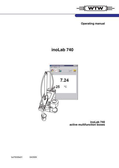
Operating manual<br />
<strong>inoLab</strong> <strong>740</strong><br />
<strong>inoLab</strong> <strong>740</strong><br />
active multifunction boxes<br />
ba75530e01 04/2005<br />
DRAFT: Wednesday, 20. April 2005
Accuracy when<br />
going to press<br />
The use of advanced technology and the high quality standard of our<br />
instruments are the result of continuous development. This may result<br />
in differences between this operating manual and your instrument.<br />
Also, we cannot guarantee that there are absolutely no errors in this<br />
manual. Therefore, we are sure you will understand that we cannot<br />
accept any legal claims resulting from the data, figures or descriptions.<br />
Warranty<br />
We guarantee the instrument described for 3 years from the date of<br />
purchase.<br />
The instrument warranty covers manufacturing faults that are<br />
discovered within the warranty period.<br />
The warranty does not cover components that are replaced during<br />
maintenance work, e. g. batteries.<br />
The warranty claim extends to restoring the instrument to readiness for<br />
use but not, however, to any further claim for damages. Improper<br />
handling or unauthorized opening of the instrument invalidates any<br />
warranty claim.<br />
To ascertain the warranty liability, return the instrument and proof of<br />
purchase together with the date of purchase freight paid or prepaid.<br />
Copyright<br />
© Weilheim 2005, WTW GmbH<br />
Reproduction in whole - or even in part - is prohibited without the<br />
express written permission of WTW GmbH, Weilheim.<br />
Printed in Germany.
<strong>inoLab</strong> <strong>740</strong><br />
Contents<br />
1 Overview . . . . . . . . . . . . . . . . . . . . . . . . . . . . . . . . . . . . . . 5<br />
1.1 Active multifunction box . . . . . . . . . . . . . . . . . . . . . . . . . . 6<br />
2 Safety . . . . . . . . . . . . . . . . . . . . . . . . . . . . . . . . . . . . . . . . 7<br />
2.1 Authorized use . . . . . . . . . . . . . . . . . . . . . . . . . . . . . . . . . 8<br />
2.2 General safety instructions . . . . . . . . . . . . . . . . . . . . . . . . 8<br />
3 Commissioning . . . . . . . . . . . . . . . . . . . . . . . . . . . . . . . 11<br />
3.1 Preparing the <strong>inoLab</strong> <strong>740</strong> measuring system . . . . . . . . . 12<br />
3.2 Connecting active multifunction boxes to the PC . . . . . . 15<br />
3.3 Additional devices/options . . . . . . . . . . . . . . . . . . . . . . . 18<br />
3.4 Installing the MultiLab ® pilot . . . . . . . . . . . . . . . . . . . . . . 19<br />
4 Maintenance, cleaning, disposal . . . . . . . . . . . . . . . . . 21<br />
5 What to do if... . . . . . . . . . . . . . . . . . . . . . . . . . . . . . . . . 23<br />
5.1 PC messages . . . . . . . . . . . . . . . . . . . . . . . . . . . . . . . . . 23<br />
5.2 pH/voltage system messages . . . . . . . . . . . . . . . . . . . . 24<br />
5.3 Ion concentration system messages . . . . . . . . . . . . . . . 26<br />
5.4 D. O. system messages . . . . . . . . . . . . . . . . . . . . . . . . 28<br />
5.5 Conductivity system messages . . . . . . . . . . . . . . . . . . . 29<br />
6 Technical data . . . . . . . . . . . . . . . . . . . . . . . . . . . . . . . . 31<br />
6.1 pH/voltage . . . . . . . . . . . . . . . . . . . . . . . . . . . . . . . . . . . 33<br />
6.2 Ion concentration . . . . . . . . . . . . . . . . . . . . . . . . . . . . . . 35<br />
6.3 Dissolved oxygen . . . . . . . . . . . . . . . . . . . . . . . . . . . . . . 36<br />
6.4 Conductivity . . . . . . . . . . . . . . . . . . . . . . . . . . . . . . . . . . 38<br />
7 Lists . . . . . . . . . . . . . . . . . . . . . . . . . . . . . . . . . . . . . . . . . 41<br />
ba75530e01 04/2005<br />
3
Contents <strong>inoLab</strong> <strong>740</strong><br />
4 ba75530e01 04/2005
<strong>inoLab</strong> <strong>740</strong><br />
Overview<br />
1 Overview<br />
<strong>inoLab</strong> <strong>740</strong> active multifunction boxes (measuring modules) can be<br />
operated via a PC or an <strong>inoLab</strong> Terminal <strong>740</strong>.<br />
The present manual describes the connection of an <strong>inoLab</strong> <strong>740</strong> active<br />
multifunction box to a PC.<br />
Remote control using the MultiLab ® pilot software is described in the<br />
operating manual of the software. The current version of the MultiLab ®<br />
pilot software is available on the Internet under http://www.WTW.com.<br />
Connection to an <strong>inoLab</strong> Terminal <strong>740</strong> and remote control using the<br />
terminal is described in the <strong>inoLab</strong> <strong>740</strong> with Terminal <strong>740</strong> operating<br />
manual.<br />
Note<br />
Information on accessories is given in the WTW catalog, LABORATORY<br />
AND FIELD INSTRUMENTATION, or on the Internet.<br />
More information or installation instructions can be requested from<br />
WTW:<br />
! Application reports<br />
! Primers<br />
! Safety datasheets.<br />
Hardware requirements<br />
Software requirements<br />
! Computer with Pentium processor or higher<br />
! A minimum of 128 Mbytes RAM<br />
! Hard disk with at least 200 Mbytes available memory<br />
! CD-ROM drive<br />
! One free USB or serial COM interface (RS232C) for each meter to<br />
be connected.<br />
! Windows 98SE or higher.<br />
ba75530e01 04/2005<br />
5
RUN<br />
ENTER<br />
AR<br />
<strong>inoLab</strong><br />
Overview <strong>inoLab</strong> <strong>740</strong><br />
1.1 Active multifunction box<br />
Each active mutifunction box has its own software in order to process<br />
the probe signals and to communicate with the terminal or PC.<br />
Active multifunction box<br />
RUN<br />
ENTER<br />
1<br />
2<br />
AR<br />
3<br />
Operating elements<br />
of the active<br />
multifunction box<br />
1 Status indicator of the AutoRead function<br />
LED off: AutoRead function is deactivated<br />
LED illuminates: AutoRead function is active<br />
LED flashes: AutoRead measurement has been started<br />
2 : Start AutoRead measurement (if the AutoRead function<br />
is active)<br />
Save the current measured value into the file for the manual<br />
storage last opened<br />
3 : Activate/deactivate the AutoRead function<br />
6 ba75530e01 04/2005
<strong>inoLab</strong> <strong>740</strong><br />
Safety<br />
2 Safety<br />
This operating manual contains basic instructions that you must follow<br />
during the commissioning, operation and maintenance of the <strong>inoLab</strong><br />
<strong>740</strong> measuring system. Consequently, all responsible personnel must<br />
read this operating manual before working with the measuring system.<br />
The operating manual must always be available within the vicinity of the<br />
measuring system.<br />
Target group<br />
The measuring system was developed for use in the laboratory.<br />
Thus, we assume that, as a result of their professional training and<br />
experience, the operators will know the necessary safety precautions<br />
to take when handling chemicals.<br />
Symbols<br />
used<br />
Caution<br />
indicates safety instructions that must be followed to prevent<br />
damage to persons and property.<br />
Note<br />
indicates notes that draw your attention to special features.<br />
Note<br />
indicates cross-references to other documents, e.g. application<br />
reports, operating manuals of electrodes, etc.<br />
ba75530e01 04/2005<br />
7
Safety <strong>inoLab</strong> <strong>740</strong><br />
2.1 Authorized use<br />
This measuring system is authorized exclusively for potentiometric,<br />
conductimetric or amperometric measurements in the laboratory.<br />
The technical specifications as given in chapter 6 TECHNICAL DATA must<br />
be observed. Only the operation and running of the measuring<br />
instrument according to the instructions given in this operating manual<br />
is authorized.<br />
Any other use is considered unauthorized.<br />
2.2 General safety instructions<br />
This measuring system is constructed and tested in compliance with<br />
the EN 61010-1 safety regulations for electronic measuring<br />
instruments.<br />
It left the factory in a safe and secure technical condition.<br />
Function and<br />
operational safety<br />
The smooth functioning and operational safety of the measuring<br />
system can only be guaranteed if the generally applicable safety<br />
measures and the specific safety instructions in this operating manual<br />
are followed during operation.<br />
The smooth functioning and operational safety of the measuring<br />
system can only be guaranteed under the environmental conditions<br />
that are specified in chapter 6 TECHNICAL DATA.<br />
If the measuring system was transported from a cold environment to a<br />
warm environment, the formation of condensate can impair the<br />
functioning of the meter. In this event, wait until the temperature of the<br />
measuring system reaches room temperature before putting the meter<br />
back into operation.<br />
Caution<br />
The measuring system is only allowed to be opened by personnel<br />
authorized by WTW.<br />
8 ba75530e01 04/2005
<strong>inoLab</strong> <strong>740</strong><br />
Safety<br />
Safe operation<br />
If safe operation is no longer possible, the measuring system must be<br />
taken out of service and secured against inadvertent operation!<br />
Safe operation is no longer possible if the measuring system<br />
! has been damaged in transport<br />
! has been stored under adverse conditions for a lengthy period of<br />
time<br />
! is visibly damaged<br />
! no longer operates as described in this manual.<br />
If you are in any doubt, please contact the supplier of the measuring<br />
system.<br />
Obligations of the<br />
purchaser<br />
The purchaser of this measuring system must ensure that the following<br />
laws and guidelines are observed when using dangerous substances:<br />
! EEC directives for protective labor legislation<br />
! National protective labor legislation<br />
! Safety regulations<br />
! Safety datasheets of the chemical manufacturers.<br />
ba75530e01 04/2005<br />
9
Safety <strong>inoLab</strong> <strong>740</strong><br />
10 ba75530e01 04/2005
<strong>inoLab</strong> <strong>740</strong><br />
Commissioning<br />
3 Commissioning<br />
Caution<br />
The measuring module is supplied with low voltage (5 V DC)<br />
either over a USB interface or over a keyboard interface on the PC.<br />
For connection on the USB interface only use the original AK 340/<br />
B cable with the ADA USB/Ser adapter.<br />
For connection on the keyboard interface only use the original<br />
AK 340/B cable to supply the active multifunction box with power.<br />
Note<br />
The MultiLab ® pilot software works together with all <strong>inoLab</strong> <strong>740</strong><br />
multifunction boxes.<br />
ba75530e01 04/2005<br />
11
<strong>inoLab</strong><br />
Commissioning <strong>inoLab</strong> <strong>740</strong><br />
3.1 Preparing the <strong>inoLab</strong> <strong>740</strong> measuring system<br />
A measuring system ready for operation comprises the following:<br />
1<br />
11<br />
2<br />
3<br />
4<br />
10<br />
9<br />
8<br />
7<br />
AR<br />
RUN<br />
ENTER<br />
5<br />
6<br />
1 Cable holder<br />
2 Stand rod<br />
3 Opening to the cable shaft<br />
4 Connection cable to the PC (AK M-PC)<br />
5 Keys to measure with AutoRead and to store measured<br />
values<br />
6 Locking holder<br />
7 Beaker with test sample<br />
8 Probe<br />
9 Freely adjustable probe holder<br />
10 Locking key for probe holder<br />
11 Connection cable: Probe - active multifunction box<br />
12 ba75530e01 04/2005
<strong>inoLab</strong> <strong>740</strong><br />
Commissioning<br />
Perform the following activities before commissioning the system:<br />
! prepare the active multifunction box and probe(s)<br />
! connect the active multifunction box to the PC<br />
! install and start the MultiLab ® pilot software<br />
Preparing the active<br />
multifunction box<br />
1 Place the active multifunction box on a flat surface and protect<br />
it from intense light and heat.<br />
2 Insert the stand rod (2) in the active multifunction box.<br />
3 Fix the probe holder (9) on the stand rod.<br />
4 Adjust the height of the probe holder (9) using the locking key<br />
(10).<br />
Connecting the probe<br />
5 Place the probe (8) into the probe holder (9).<br />
6 Place the cable (11) of the probe (8) in the cable holder (1) at<br />
the stand rod or at the probe holder (9).<br />
12 pH/ORP electrode or ion sensitive electrode<br />
13 D. O. probe or conductivity measuring cell<br />
14 Stirrer connection for D. O. probe StirrOx G<br />
15 Reference electrode<br />
16 Temperature sensor<br />
Caution<br />
Only connect probes to the active multifunction box that cannot<br />
feed excessive voltages or currents (> SELV and > circuit with<br />
current limiter). Almost all commercial electrodes - especially<br />
WTW electrodes - meet these requirements.<br />
ba75530e01 04/2005<br />
13
Commissioning <strong>inoLab</strong> <strong>740</strong><br />
7 Connect the probe (8) to the relevant socket (12 or 13) of the<br />
active multifunction box.<br />
8 If necessary, connect the plug for the temperature probe in the<br />
probe to the socket (16).<br />
9 Prepare the beaker with the test solution (7).<br />
10 Adjust the height of the probe holder (9) by pressing the locking<br />
key (10) so that the probe (8) is immersed in the test solution.<br />
11 for pH, ORP or ISE electrodes with separate<br />
reference electrodes:<br />
Connect the reference electrode to the socket (15).<br />
12 Put the probe cable (11) into the cable shaft (3) so that it is<br />
stored safely.<br />
14 ba75530e01 04/2005
RS-232<br />
TO USB<br />
<strong>inoLab</strong> <strong>740</strong><br />
Commissioning<br />
3.2 Connecting active multifunction boxes to the PC<br />
You can run up to four active multifunction boxes on a PC.<br />
Communication of multifunction box and PC takes place via a USB or<br />
serial COM interface.<br />
USB interface<br />
1 Plug the USB plug (2) of the Ada USB/Ser adapter into a USB<br />
interface of the PC. The USB interface can be used for serial<br />
plugs.<br />
3<br />
2<br />
2 Using the AK 340/B connection cable, connect the serial<br />
connection of the USB adapter (3) to the RS232 socket (1) of<br />
the multifunction box.<br />
Up to four active multifunction boxes can be connected to the PC. Four<br />
AK 340/B connection cables and four Ada USB/Ser USB adapters are<br />
required for this.<br />
1<br />
ba75530e01 04/2005<br />
15
Commissioning <strong>inoLab</strong> <strong>740</strong><br />
Serial interface<br />
Connection to the PC is made using the AK M-PC cable.<br />
The AK M-PC cable has a PS2 plug and socket.<br />
Communication between the active multifunction box and PC takes<br />
place via the serial interface. The power required by the active<br />
multifunction box is taken from the PC via the transition piece on the<br />
connection cable between the keyboard and PC.<br />
Note<br />
If your PC has a DIN keyboard interface instead of the PS2 keyboard<br />
interface, connect the PS2 - DIN adapter provided to the PS2 plug (3)<br />
and the PS2 socket (2) of the AK M-PC connection cable.<br />
If your PC has a free 25-pin serial interface instead of the free 9-pin<br />
interface, connect the 9/25 adapter provided to the 9-pin COM plug (4).<br />
1 Disconnect the existing PC keyboard from the PC.<br />
2 Connect the PS2 plug (3) of the AK M-PC connection cable to<br />
the keyboard interface on the PC.<br />
2<br />
3<br />
4<br />
5<br />
3 Plug the PC keyboard into the socket (2) of the AK M-PC<br />
connection cable.<br />
4 Plug the RS232 plug (4) of the AK M-PC connection cable into<br />
a serial interface (COM 1 to COM 4) on the PC.<br />
5 Plug the multifunction box plug (5) of the AK M-PC connection<br />
cable into the socket (1) of the active multifunction box.<br />
16 ba75530e01 04/2005
<strong>inoLab</strong> <strong>740</strong><br />
Commissioning<br />
Up to four active multifunction boxes can be connected to the PC. To<br />
do so, four AK M-PC connection cables are required. The following<br />
example of two active multifunction boxes illustrates the principle of<br />
how to connect the cables with two or more active multifunction boxes.<br />
1<br />
6 Disconnect the PC keyboard from the socket (2).<br />
7 Connect the PS2 plug (7) of the second AK M-P cable to the<br />
socket (2) of the first AK M-PC cable.<br />
Cable 2 Cable 1<br />
6 7 2<br />
3<br />
8<br />
4<br />
9 5<br />
8 Plug the PC keyboard into the socket (6) on the second cable<br />
to the PC.<br />
9 Plug the RS232 plug (8) of the second AK M-PC cable to the<br />
PC into another serial interface (COM 1 to COM 4) on the PC.<br />
10 Plug the multifunction box plug (9) of the second AK M-PC<br />
connection cable into the socket (1) of the second active<br />
multifunction box.<br />
ba75530e01 04/2005<br />
17
Commissioning <strong>inoLab</strong> <strong>740</strong><br />
3.3 Additional devices/options<br />
11 Attach the locking holder (6) to the active multifunction box.<br />
12 Connect the external temperature probe to the sockets (15 and<br />
16) (see page 13).<br />
13 Connect the D. O. probe with stirrer (StirrOx G) to the socket<br />
(14) (see page 13).<br />
14 Connect the barcode reader to the PC keyboard interface or to<br />
the socket (7) of the second connection cable to the PC.<br />
Note<br />
Only Wedgetype barcode readers are suitable to be connected to the<br />
keyboard interface.<br />
Also observe the connection instructions in the operating manual of<br />
your barcode reader.<br />
18 ba75530e01 04/2005
<strong>inoLab</strong> <strong>740</strong><br />
Commissioning<br />
3.4 Installing the MultiLab ® pilot<br />
Note<br />
The MultiLab ® pilot software is on the CD-ROM supplied. The software<br />
is continuously developed further. The current software version is<br />
available for download on the Internet under http://www.WTW.com.<br />
1 Start the MultiLab ® pilot installation program.<br />
2 Follow the user guide.<br />
Note<br />
After the installation is finished, the Data subdirectory is the standard<br />
directory for the Save and Open functions. Here you will find some<br />
sample files, which you can also open in the offline mode.<br />
Note<br />
Remote control using the software is described in the operating manual<br />
of the MultiLab ® pilot software.<br />
ba75530e01 04/2005<br />
19
Commissioning <strong>inoLab</strong> <strong>740</strong><br />
20 ba75530e01 04/2005
<strong>inoLab</strong> <strong>740</strong><br />
Maintenance, cleaning, disposal<br />
4 Maintenance, cleaning, disposal<br />
Maintenance<br />
The measuring system is almost maintenance-free.<br />
Note<br />
See the relevant operating manuals of the probes for instructions on<br />
maintenance.<br />
Cleaning<br />
Occasionally wipe the outside of the measuring module with a damp,<br />
lint-free cloth. Disinfect the housing with isopropanol as required.<br />
Caution<br />
The housing is made of a synthetic material (ABS). Thus, avoid<br />
contact with acetone or similar detergents that contain solvents.<br />
Remove any splashes immediately.<br />
Disposal<br />
This measuring system is sent out in a protective transport packing.<br />
We recommend: Keep the packing material. The original packing<br />
protects the instrument against damage during transport.<br />
Dispose of the measuring module as electronic waste at an appropriate<br />
collection point. It is illegal to dispose of them in household refuse.<br />
ba75530e01 04/2005<br />
21
Maintenance, cleaning, disposal <strong>inoLab</strong> <strong>740</strong><br />
22 ba75530e01 04/2005
<strong>inoLab</strong> <strong>740</strong><br />
What to do if...<br />
5 What to do if...<br />
System messages due to errors are listed together with their possible<br />
causes and remedies.<br />
5.1 PC messages<br />
Red probe symbol<br />
Cause<br />
Calibration interval expired<br />
Remedy<br />
Recalibrate the measuring system<br />
Measuring module does<br />
not react to keystroke<br />
Cause<br />
Operating state undefined or<br />
electromagnetic interference too<br />
high<br />
Remedy<br />
Disconnect and then reconnect<br />
the AK M-PC cable to the<br />
measuring module (if the error<br />
occurs repeatedly, reduce the<br />
electromagnetic interference in<br />
the environment of the measuring<br />
module)<br />
Lengthy stability check<br />
with AutoRead<br />
Cause<br />
No stable measured value<br />
Defective probe<br />
Remedy<br />
Provide stable measuring<br />
conditions (e.g. temperature)<br />
Use another probe<br />
ba75530e01 04/2005<br />
23
What to do if... <strong>inoLab</strong> <strong>740</strong><br />
5.2 pH/voltage system messages<br />
For the <strong>inoLab</strong> <strong>740</strong> multifunction boxes:<br />
pH, pH/ION, pH/Cond and Multi.<br />
Error message,<br />
OFL<br />
Cause<br />
pH/voltage electrode:<br />
Remedy<br />
– Not connected – Connect electrode<br />
– Air bubble in front of the<br />
diaphragm<br />
– Remove air bubble<br />
– Air in the diaphragm – Extract air or moisten<br />
diaphragm<br />
– Cable broken – Replace electrode<br />
– Gel electrolyte dried out – Replace electrode<br />
Error message,<br />
E3<br />
Cause<br />
pH/ORP electrode:<br />
Remedy<br />
– Diaphragm contaminated – Clean diaphragm<br />
– Membrane contaminated – Clean membrane<br />
– Moisture in the plug – Dry plug<br />
– Electrolyte obsolete – Replenish electrolyte<br />
or<br />
– Replace electrode<br />
– Electrode obsolete – Replace electrode<br />
– pH electrode: broken – Replace electrode<br />
– ORP electrode: short-circuit – Replace electrode<br />
Measuring system:<br />
– Incorrect calibration procedure – Select correct procedure<br />
– Incorrect solution temperature<br />
(without temperature probe)<br />
– Set up correct temperature<br />
– Socket damp – Dry socket<br />
24 ba75530e01 04/2005
<strong>inoLab</strong> <strong>740</strong><br />
What to do if...<br />
Buffer solutions<br />
– Incorrect buffer solutions – Change calibration procedure<br />
– Buffer solutions too old – Use only once. Note the shelf<br />
life<br />
– Buffer solutions depleted – Change solutions<br />
No stable measured<br />
value<br />
Cause<br />
pH/ORP electrode:<br />
Remedy<br />
– Diaphragm contaminated – Clean diaphragm<br />
– Membrane contaminated – Clean membrane<br />
Test sample:<br />
– pH value not stable – Measure with air excluded if<br />
necessary<br />
– Temperature not stable – Adjust temperature if<br />
necessary<br />
Electrode + test sample:<br />
– Conductivity too low – Use suitable electrode<br />
– Temperature too high – Use suitable electrode<br />
– Organic liquids – Use suitable electrode<br />
Obviously incorrect<br />
measured values<br />
Cause<br />
Electrode + test sample:<br />
Remedy<br />
– pH electrode unsuitable Use suitable electrode<br />
– Temperature difference<br />
between buffer and test<br />
sample too high<br />
Adjust temperature of buffer or<br />
sample solutions<br />
ba75530e01 04/2005<br />
25
What to do if... <strong>inoLab</strong> <strong>740</strong><br />
5.3 Ion concentration system messages<br />
For the <strong>inoLab</strong> <strong>740</strong> multifunction boxes:<br />
pH, pH/ION, pH/Cond and Multi.<br />
Error message,<br />
OFL<br />
Cause<br />
Ion sensitive electrode or reference<br />
electrode<br />
Remedy<br />
– Not connected – Connect electrode<br />
– Cable broken – Replace electrode<br />
Error message,<br />
E3<br />
Cause<br />
Ion-sensitive electrode:<br />
– Slope is not in the range 50 ... 70<br />
mV or 23 ... 35 mV<br />
Remedy<br />
– Replace electrode<br />
– recalibrate<br />
– Moisture in the plug – Dry plug<br />
– Electrode obsolete – Replace electrode<br />
– Measuring in a range unsuitable<br />
for the electrode<br />
– Use a suitable electrode<br />
Measuring system:<br />
– Calibration procedure: Wrong<br />
sequence of standards for three<br />
point calibration<br />
– Select correct sequence<br />
– Socket damp – Dry socket<br />
Temp error<br />
Cause<br />
During calibration:<br />
– Calibration standards do not<br />
have the correct temperature<br />
(max. ± 2 °C temperature<br />
difference)<br />
In measurement:<br />
– Test sample does not have the<br />
correct temperature (max. ± 2<br />
°C temperature difference from<br />
calibration temperature)<br />
Remedy<br />
– Adjust the temperature of the<br />
calibration standards<br />
– Adjust the temperature of the<br />
test sample<br />
26 ba75530e01 04/2005
<strong>inoLab</strong> <strong>740</strong><br />
What to do if...<br />
Cal error Cause Remedy<br />
During calibration:<br />
– Calibration standards are too<br />
close to each other<br />
IU 2 -U 1 I ≤ 5mV<br />
IU 3 -U 2 I ≤ 5mV<br />
– Use other calibration<br />
standards<br />
In measurement:<br />
– Measured value is outside the<br />
calibration limits<br />
– Recalibrate with suitable<br />
standards as necessary<br />
ba75530e01 04/2005<br />
27
What to do if... <strong>inoLab</strong> <strong>740</strong><br />
5.4 D. O. system messages<br />
For the <strong>inoLab</strong> <strong>740</strong> multifunction boxes:<br />
Oxi, BSB/BOD and Multi.<br />
Error message,<br />
OFL<br />
Cause<br />
Display range exceeded<br />
Remedy<br />
– Not connected – Connect probe<br />
– Cable broken – Replace probe<br />
– Depleted – Replace probe<br />
– Short-circuit between gold and<br />
lead electrode<br />
– Clean probe and replace it if<br />
necessary<br />
Error message,<br />
E3<br />
Cause<br />
Invalid calibration<br />
Remedy<br />
– Electrolyte solution depleted – Regenerate probe<br />
– Membrane contaminated – Clean membrane<br />
– Electrode system poisoned – Regenerate probe<br />
– Obsolete – Replace probe<br />
– broken – Replace probe<br />
Error message,<br />
E7<br />
Cause<br />
Membrane damaged<br />
Remedy<br />
– Membrane damaged – Regenerate probe<br />
– Membrane head screwed on not<br />
tight enough<br />
– Screw membrane head tight<br />
Display of<br />
StirrerError<br />
Cause<br />
With StirrOx G probe<br />
– Current at the stirrer supply is<br />
too high<br />
Remedy<br />
– Replace the StirrOx G<br />
28 ba75530e01 04/2005
<strong>inoLab</strong> <strong>740</strong><br />
What to do if...<br />
Measured value too low<br />
Cause<br />
Probe + test sample:<br />
Remedy<br />
– Insufficient flow – Provide flow to the probe<br />
Measured value too<br />
high<br />
Cause<br />
Probe + test sample:<br />
– High amount of dissolved<br />
substances<br />
– Air bubbles bump on the<br />
membrane with high velocity<br />
– The carbon dioxide pressure is<br />
too high (> 1 bar)<br />
Remedy<br />
– Correct solubility function<br />
using the salinity equivalent<br />
– Avoid direct flow to the<br />
membrane<br />
– Measuring not possible<br />
5.5 Conductivity system messages<br />
For the <strong>inoLab</strong> <strong>740</strong> multifunction boxes:<br />
Cond, pH/Cond and Multi.<br />
Error message,<br />
OFL<br />
Cause<br />
Measuring cell + test sample:<br />
Remedy<br />
– Measuring cell not connected – Connect measuring cell<br />
– Cable broken – Replace measuring cell<br />
– The measured value is outside<br />
the measuring range<br />
Error message,<br />
E3<br />
Cause<br />
Measuring cell + test sample:<br />
Remedy<br />
– Measuring cell contaminated – Clean cell and replace it if<br />
necessary<br />
– Calibration solution not suitable – Check calibration solutions<br />
ba75530e01 04/2005<br />
29
What to do if... <strong>inoLab</strong> <strong>740</strong><br />
30 ba75530e01 04/2005
<strong>inoLab</strong> <strong>740</strong><br />
Technical data<br />
6 Technical data<br />
Ambience conditions<br />
Storage - 25 °C ... + 65 °C<br />
Operation 0 °C ... + 40 °C<br />
Admissible relative<br />
humidity<br />
Yearly mean: < 75 %<br />
30 days /year: 95 %<br />
Other days: 85 %<br />
Mechanical structure<br />
Type of protection IP 43 without integrated printing device<br />
Climatic class 2<br />
Electrical safety<br />
Protective class 3<br />
Guidelines<br />
and norms used<br />
EMC<br />
E.C. guideline 89/336/EEC<br />
EN 61326-1:1998<br />
EN 61000-3-2 A14:2000<br />
EN 61000-3-3:1995<br />
FCC Class A<br />
Instrument safety E.C. directive 73/23/EEC<br />
EN 61010-1 A2:1995<br />
Climatic class VDI/VDE 3540<br />
Type of protection EN 60529:1991<br />
Protective class EN 61010-1<br />
Test certificates<br />
CETLUS, CE<br />
Dimensions and weight<br />
Length [mm] 300<br />
Width [mm] 100<br />
Height [mm]<br />
(without stand)<br />
(with stand)<br />
170<br />
500<br />
Weight [kg] approx. 1.3<br />
ba75530e01 04/2005<br />
31
Technical data <strong>inoLab</strong> <strong>740</strong><br />
Power supply<br />
The power is supplied via the connection cable from the PC.<br />
Voltage 5V ± 10%<br />
Current<br />
max. 500mA<br />
FCC Class A Equipment Statement<br />
Note: This equipment has been tested and found to comply with<br />
the limits for a Class A digital device, pursuant to Part 15 of the<br />
FCC Rules. These limits are designed to provide reasonable<br />
protection against harmful interference when the equipment is<br />
operated in a commercial environment. This equipment<br />
generates, uses, and can radiate radio frequency energy and, if<br />
not installed and used in accordance with the instruction manual,<br />
may cause harmful interference to radio communications.<br />
Operation of this equipment in a residential area is likely to cause<br />
harmful interference in which case the user will be required to<br />
correct the interference at his own expense.<br />
32 ba75530e01 04/2005
<strong>inoLab</strong> <strong>740</strong><br />
Technical data<br />
6.1 pH/voltage<br />
Note<br />
The technical data of the electrodes are not taken into account here.<br />
General information<br />
Input resistance<br />
Input current<br />
Slope (pH)<br />
Asymmetry (pH)<br />
5 x 10 12 Ω<br />
5 x 10 -13 A typical<br />
< 5 x 10 -12 A at 25°C<br />
-62 ... -50 mV<br />
-30 ... +30 mV<br />
Measuring ranges and<br />
resolution<br />
pH<br />
Measuring range 1 (resolution) - 2.000 ... + 19.999 (0.001)<br />
Measuring range 2 (resolution) - 2.00 ... + 19.99 (0.01)<br />
Voltage U [mV]<br />
Measuring range 1 (resolution) - 999.9 ... + 999.9 (0.1)<br />
Measuring range 2 (resolution) - 1999 ... + 1999 (1)<br />
Temperature<br />
T [°C] (resolution) - 5.0 ... + 100.0 (0.1)<br />
T [°F] (resolution) + 23.0 ... + 212.0 (0.1)<br />
ba75530e01 04/2005<br />
33
Technical data <strong>inoLab</strong> <strong>740</strong><br />
Accuracy (± 1 digit)<br />
pH (± 2 units around the calibration point)<br />
Measuring range 1<br />
Measuring range 2<br />
± 0.004 at + 15°C ... + 35°C<br />
± 0.01<br />
Voltage U [mV]<br />
Measuring range 1<br />
Measuring range 2<br />
± 0.2 at + 15°C ... + 35°C<br />
± 1<br />
Temperature<br />
T [°C] NTC 30:<br />
± 0.1<br />
PT 1000 (1) :<br />
± 0.5 at 0°C ... 15°C<br />
± 0.1 at 15°C ... 35°C<br />
± 1 at 35°C ... 55°C<br />
T [°F] NTC 30:<br />
± 0.2<br />
PT 1000 (1) :<br />
± 0.9 at 32°F ... 59°F<br />
± 0.2 at 59°F ... 95°F<br />
± 1.8 at 95°F ... 131°F<br />
(1) Operation of the PT 1000 temperature probe is possible on<br />
the measuring modules, <strong>inoLab</strong> pH <strong>740</strong> and pH/ION <strong>740</strong><br />
only.<br />
Temperature input<br />
Manually [°C] - 20 ... + 130<br />
Electrodes &<br />
accessories<br />
Information on electrodes to be used and other accessories is given in<br />
the WTW catalog, LABORATORY AND FIELD INSTRUMENTATION, or is<br />
available on the Internet.<br />
34 ba75530e01 04/2005
<strong>inoLab</strong> <strong>740</strong><br />
Technical data<br />
6.2 Ion concentration<br />
Note<br />
The technical data of the electrodes are not taken into account here.<br />
General information<br />
Input resistance<br />
Input current<br />
Slope ranges<br />
5 x 10 12 Ω<br />
5 x 10 -13 A typical<br />
< 5 x 10 -12 A at 25°C<br />
± 25 to 35 mV and<br />
± 50 to 70 mV<br />
Measuring ranges and<br />
resolution<br />
Concentration [mg/l]<br />
Measuring range 1 (resolution) 0.000 ... 9.999 (0.001)<br />
Measuring range 2 (resolution) 0.00 ... 99.9 (0.01)<br />
Measuring range 3 (resolution) 0.0 ... 999.9 (0.1)<br />
Measuring range 4 (resolution) 0 ... 1999 (1)<br />
Temperature<br />
T [°C] (resolution) - 5.0 ... + 100.0 (0.1)<br />
T [°F] (resolution) + 23.0 ... + 212.0 (0.1)<br />
Electrodes &<br />
accessories<br />
Information on electrodes to be used and other accessories is given in<br />
the WTW catalog, LABORATORY AND FIELD INSTRUMENTATION, or is<br />
available on the Internet.<br />
ba75530e01 04/2005<br />
35
Technical data <strong>inoLab</strong> <strong>740</strong><br />
6.3 Dissolved oxygen<br />
Note<br />
The technical data of the probes are not taken into account here.<br />
Measuring ranges and<br />
resolution<br />
Concentration [mg/l]<br />
Measuring range 1 (resolution) 0 ... 19.99 (0.01)<br />
Measuring range 2 (resolution) 0 ... 90.0 (0.1)<br />
Saturation [%]<br />
Measuring range 1 (resolution) 0 ... 199.9 (0.1 )<br />
Measuring range 2 (resolution) 0 ... 600 (1)<br />
D. O. partial pressure [mbar]<br />
Measuring range 1 (resolution) 0 ... 199.9 (0.1)<br />
Measuring range 2 (resolution) 0 ... 1250 (1)<br />
Temperature<br />
T [°C] (resolution) 0.0 ... 50.0 (0.1)<br />
T [°F] (resolution) + 32.0 ... + 122.0 (0.1)<br />
36 ba75530e01 04/2005
<strong>inoLab</strong> <strong>740</strong><br />
Technical data<br />
Accuracy (±1 digit)<br />
Concentration<br />
± 0.5% of measured value<br />
at ambient temperature of 5 °C ... 30 °C<br />
Temperature compensation<br />
< 2 % at 0 ... 40 °C<br />
Saturation<br />
± 0.5% of measured value<br />
when measuring in a range of<br />
± 10 K around the calibration temperature<br />
Oxygen partial pressure<br />
± 0.5% of measured value<br />
at ambient temperature of 5 °C ... 30 °C<br />
Temperature<br />
T [°C] ± 0.1<br />
T [°F] ± 0.2<br />
Correction functions<br />
Salinity<br />
correction<br />
Air pressure<br />
correction<br />
0 ... 70.0 SAL<br />
automatically using the built-in pressure sensor in<br />
the range 500 ... 1100 mbar<br />
Probes & accessories<br />
Information on electrodes to be used and other accessories is given in<br />
the WTW catalog, LABORATORY AND FIELD INSTRUMENTATION, or is<br />
available on the Internet.<br />
ba75530e01 04/2005<br />
37
Technical data <strong>inoLab</strong> <strong>740</strong><br />
6.4 Conductivity<br />
Note<br />
The technical data of the measuring cells are not taken into account<br />
here.<br />
Measuring ranges and<br />
resolution<br />
Conductivity [µS/cm]<br />
Measuring range 1 (resolution) 0.000 ... 1.999 (0.001)<br />
(at cell const. = 0.01 cm -1 )<br />
Measuring range 2 (resolution) 0.00 ... 19.99 (0.01)<br />
(at cell const. = 0.01 cm -1 or 0.1 cm -1 )<br />
Measuring range 3 (resolution) 0.0 ... 199.9 (0.1)<br />
Measuring range 4 (resolution) 0 ... 1999 (1)<br />
Conductivity [mS/cm]<br />
Measuring range 5 (resolution) 0.00 ... 19.99 (0.01)<br />
Measuring range 6 (resolution) 0.0 ... 199.9 (0.1)<br />
Measuring range 7 (resolution) 0 ... 500 (1)<br />
Specific resistance [MΩcm]<br />
Measuring range 1 (resolution) 0.000 ... 1.999 (0.001)<br />
Measuring range 2 (resolution) 0.00 ... 19.99 (0.01)<br />
Measuring range 3 (resolution) 0.0 ... 199.9 (0.1)<br />
Measuring range 4 (resolution) 0 ... 1999 (1)<br />
Salinity equivalents according to IOT table<br />
SAL 0.0 ... 70.0<br />
Total dissolved solids TDS [mg/l]<br />
Measuring range (resolution)<br />
Adjustable factor<br />
0 ... 1999 (1)<br />
0.40 ... 1.00<br />
38 ba75530e01 04/2005
<strong>inoLab</strong> <strong>740</strong><br />
Technical data<br />
Temperature<br />
T [°C] (resolution) − 5.0 ... + 100.0 (0.1)<br />
T [°F] (resolution) + 23.0 ... + 212.0 (0.1)<br />
Accuracy (± 1 digit)<br />
Conductivity, specific resistance<br />
No temperature<br />
compensation<br />
Nonlinear temperature<br />
compensation<br />
Linear temperature<br />
compensation<br />
± 0.5 %<br />
± 0.5 %<br />
(at 0°C ... 35°C according to EN 27 888)<br />
± 0.5 %<br />
(at 35°C ... 50°C extended nLF function<br />
according to WTW measurements)<br />
± 0.5 % 10°C ... 75°C<br />
(the accuracy percentage always relates to<br />
the measured value!)<br />
Salinity equivalent SAL<br />
Range<br />
0.0 ... 42.0<br />
± 0.1 (at 5°C ... 25°C)<br />
± 0.2 (at 25°C ... 30°C)<br />
Total dissolved solids TDS [mg/l]<br />
± 1<br />
ba75530e01 04/2005<br />
39
Technical data <strong>inoLab</strong> <strong>740</strong><br />
Temperature<br />
T [°C] NTC 30<br />
Accuracy ± 0.1<br />
PT 1000 (1) :<br />
Accuracy Operating temperature<br />
± 0.5 at 0°C ... 15°C<br />
± 0.1 at 15°C ... 35°C<br />
± 1 at 5°C ... 55°C<br />
T [°F] NTC 30:<br />
Accuracy ± 0.2<br />
PT 1000 (1) :<br />
Accuracy Operating temperature<br />
± 0.9 at 32°F ... 59°F<br />
± 0.2 at 59°F ... 95°F<br />
± 1.8 at 95°F ... 131°F<br />
(1) Operation of the PT 1000 temperature probe is possible on<br />
the measuring module, <strong>inoLab</strong> Cond <strong>740</strong> only.<br />
Setting the cell<br />
constant<br />
C [cm -1 ]<br />
(1)<br />
0.01<br />
0.090 ... 0.110 or 0.1 (1)<br />
0.250 ... 2.500<br />
(1) for <strong>inoLab</strong> Cond <strong>740</strong> only<br />
Cell constant,<br />
calibrated<br />
C [cm -1 ] 0.450 ... 0.500<br />
0.800 ... 1.200<br />
Reference temperature,<br />
selectable<br />
TREF [°C] 20<br />
25<br />
Measuring cells &<br />
accessories<br />
Information on measuring cells to be used and other accessories is<br />
given in the WTW catalog, LABORATORY AND FIELD INSTRUMENTATION,<br />
or is available on the Internet.<br />
40 ba75530e01 04/2005
<strong>inoLab</strong> <strong>740</strong><br />
Lists<br />
7 Lists<br />
This chapter provides additional information and orientation aids.<br />
Abbreviations<br />
The list of abbreviations explains display indicators and abbreviations<br />
used.<br />
Specialist terms<br />
The glossary briefly explains the meaning of the specialist terms.<br />
However, terms that should already be familiar to the target group are<br />
not described here.<br />
Index<br />
The index helps you to find the topics that you are looking for.<br />
ba75530e01 04/2005<br />
41
Lists <strong>inoLab</strong> <strong>740</strong><br />
Abbreviations<br />
Conductivity value (international γ)<br />
AR<br />
ARng<br />
ASY<br />
AutoCal DIN<br />
AutoCal TEC<br />
AutoRead (drift control)<br />
Automatic range switchover;<br />
meter measures with highest resolution<br />
Asymmetry<br />
Automatic pH calibration with buffer solutions<br />
prepared according to DIN 19 266<br />
Automatic pH calibration with WTW technical<br />
buffer solutions according to DIN 19267<br />
C Cell constant [cm -1 ] (internat. k)<br />
°C Temperature unit, degrees Celsius<br />
Cal<br />
Cd...<br />
Cm...<br />
ConCal<br />
Ct...<br />
Calibration<br />
Display indicator during calibration for pH<br />
measurements. Indicates the selection of the<br />
buffer dataset for buffer solutions prepared<br />
according to DIN 19 266<br />
Display indicator during calibration for pH<br />
measurements. Indicates the selection of buffer<br />
datasets for buffer solutions of the Merck company<br />
Conventional single-point or two-point calibration<br />
for pH measurements<br />
Display indicator during calibration for pH<br />
measurements. Indicates the selection of the<br />
buffer data records for WTW technical buffer<br />
solutions<br />
E3<br />
Error message, see chapter 5 WHAT TO DO<br />
IF...<br />
°F Temperature unit, degrees Fahrenheit<br />
ISECal<br />
Lin<br />
mV<br />
mV/pH<br />
nLF<br />
Calibration for ion selective measurements<br />
Linear temperature compensation<br />
Voltage unit<br />
Unit of the electrode slope (internat. mV)<br />
Nonlinear temperature compensation<br />
42 ba75530e01 04/2005
<strong>inoLab</strong> <strong>740</strong><br />
Lists<br />
OFL<br />
OxiCal<br />
pH<br />
Display range exceeded (Overflow)<br />
Automatic calibration for D. O. measurements<br />
pH value<br />
S Slope (internat. k)<br />
SAL<br />
SELV<br />
SLO<br />
Salinity<br />
Safety Extra Low Voltage<br />
Slope setting on calibration<br />
TC Temperature coefficient (internat. α)<br />
TDS<br />
TP<br />
Total Dissolved Solids<br />
Temperature measurement active (Temperature<br />
Probe)<br />
T Ref 20/T20 Reference temperature of 20 °C<br />
T Ref 25/T25 Reference temperature of 25 °C<br />
U ASY<br />
Asymmetry<br />
ba75530e01 04/2005<br />
43
Lists <strong>inoLab</strong> <strong>740</strong><br />
Glossary<br />
Activity<br />
Adjusting<br />
Amperometry<br />
Asymmetry<br />
AutoRange<br />
AutoRead<br />
Calibration<br />
Cell constant, k<br />
Conductivity<br />
Conductometry<br />
Electrode zero point<br />
Electromotive force<br />
of an electrode<br />
The activity corresponds to the effective concentration. Due to mutual<br />
interference, the effect of ions is different from the value that is<br />
theoretically to be expected, e.g. with electrochemical processes.<br />
With small to medium concentrations (< 1 mol/kg), the ion activity of<br />
ions is lower than their concentration. The interrelationship between<br />
the activity a and concentration c is expressed by the equation, a i =f i<br />
x c i .<br />
To manipulate a measuring system so that the relevant value (e. g. the<br />
displayed value) differs as little as possible from the correct value or<br />
a value that is regarded as correct, or that the difference remains<br />
within the tolerance.<br />
Name of a measuring technique. The signal (depending on the<br />
measured parameter) of the probe is the electric current. The<br />
electrical voltage remains constant.<br />
Designation for the offset potential of a pH electrode. It is the<br />
measurable potential of a symmetrical electrode, the membrane of<br />
which is immersed in a solution with the pH of the nominal electrode<br />
zero point (WTW electrodes: pH = 7).<br />
Name of the automatic selection of the measuring range.<br />
WTW name for a function to check the stability of the measured value.<br />
Comparing the value from a measuring system (e. g. the displayed<br />
value) to the correct value or a value that is regarded as correct.<br />
Often, this expression is also used when the measuring system is<br />
adjusted at the same time (see adjusting).<br />
Characteristic quantity of a conductivity measuring cell, depending on<br />
the geometry.<br />
Short form of the expression, specific electrical conductivity. It is a<br />
measured value of the ability of a substance to conduct an electric<br />
current. In water analysis, the electrical conductivity is a dimension for<br />
the ionized substances in a solution.<br />
Name of the conductivity measuring technique.<br />
The zero point of a pH electrode is the pH value at which the<br />
electromotive force of the pH electrode at a specified temperature is<br />
zero. Normally, this is at 25 °C.<br />
The electromotive force U of the electrode is the measurable<br />
electromotive force of an electrode in a solution. It equals the sum of<br />
all the galvanic voltages of the electrode. Its dependency on the pH<br />
results in the electrode function which is characterized by the<br />
parameters, slope and zero point.<br />
44 ba75530e01 04/2005
<strong>inoLab</strong> <strong>740</strong><br />
Lists<br />
Firmware<br />
Junction<br />
Measured value<br />
Measured variable<br />
Measuring system<br />
Molality<br />
MultiCal ®<br />
Offset potential<br />
ORP voltage<br />
OxiCal ®<br />
Oxygen partial<br />
pressure<br />
Oxygen saturation<br />
pH value<br />
Potentiometry<br />
Software installed at an instrument (here: measuring module) that is<br />
fixed and cannot be changed.<br />
The junction is a porous body in the housing wall of reference<br />
electrodes or electrolyte bridges. It arranges the electrical contact<br />
between two solutions and makes the electrolyte exchange more<br />
difficult. The expression, junction, is also used for ground or junctionless<br />
transitions.<br />
The measured value is the special value of a measured parameter to<br />
be determined. It is given as a combination of the numerical value and<br />
unit (e. g. 3 m;0.5 s; 5.2 A; 373.15 K).<br />
The measured parameter is the physical dimension determined by<br />
measuring, e. g. pH, conductivity or D. O. concentration.<br />
The measuring system comprises all the devices used for measuring,<br />
e. g. measuring instrument and probe. In addition, there is the cable<br />
and possibly an amplifier, terminal strip and armature.<br />
Molality is the quantity (in Mol) of a dissolved substance in 1000 g<br />
solvent.<br />
WTW name stating that a measuring instrument provides several<br />
calibration procedures.<br />
The measurable potential of a symmetrical electrode, the membrane<br />
of which is immersed in a solution with the pH of the nominal electrode<br />
zero point. The asymmetry is part of the offset potential.<br />
The ORP is caused by oxidizing or reducing substances dissolved in<br />
water if these substances become effective on an electrode surface<br />
(e. g. a gold or platinum surface).<br />
WTW name for a procedure to calibrate D. O. measuring systems in<br />
water vapor saturated air.<br />
Pressure caused by the oxygen in a gas mixture or liquid.<br />
Short name for the relative D. O. saturation.<br />
Note: The D. O. saturation value of air-saturated water and the D. O.<br />
saturation value of oxygen-saturated water are different.<br />
The pH is a dimension for the acidic or basic effect of an aqueous<br />
solution. It corresponds to the negative decadic logarithm of the molal<br />
hydrogen ions activity divided by the unit of the molality. The practical<br />
pH value is the value of a pH measurement.<br />
Name of a measuring technique. The signal (depending on the<br />
measured parameter) of the electrode is the electrical potential. The<br />
electrical current remains constant.<br />
ba75530e01 04/2005<br />
45
Lists <strong>inoLab</strong> <strong>740</strong><br />
Reference<br />
temperature<br />
Reset<br />
Resistance<br />
Resolution<br />
Salinity<br />
Salt content<br />
Slope<br />
Slope (relative)<br />
Standard solution<br />
TDS<br />
Temperature<br />
coefficient<br />
Temperature<br />
compensation<br />
Temperature<br />
function<br />
Test sample<br />
Fixed temperature value to compare temperature-dependent<br />
measured values. For conductivity measurements, the measured<br />
value is converted to a conductivity value at a reference temperature<br />
of 20 °C or 25 °C.<br />
Restoring the original condition of all settings of a measuring system.<br />
Short name for the specific electrolytic resistance. It corresponds to<br />
the reciprocal value of the electrical conductivity.<br />
Smallest difference between two measured values that can be<br />
displayed by a measuring instrument.<br />
The absolute salinity S A of seawater corresponds to the relationship<br />
of the mass of dissolved salts to the mass of the solution (in g/Kg). In<br />
practice, this dimension cannot be measured directly. Therefore, the<br />
practical salinity is used for oceanographic monitoring. It is<br />
determined by measuring the electrical conductivity.<br />
General designation for the quantity of salt dissolved in water.<br />
The slope of a linear calibration function.<br />
Designation used by WTW in the D. O. measuring technique. It<br />
expresses the relation of the slope value to the value of a theoretical<br />
reference probe of the same construction type.<br />
The standard solution is a solution where the measured value is<br />
known by definition. It is used to calibrate a measuring system.<br />
Total dissolved solids<br />
Value of the slope of a linear temperature function.<br />
Name of a function that considers the temperature influence on the<br />
measurement and converts it accordingly. Depending on the<br />
measured parameter to be determined, the temperature<br />
compensation functions in different ways. For conductimetric<br />
measurements, the measured value is converted to a defined<br />
reference temperature. For potentiometric measurements, the slope<br />
value is adjusted to the temperature of the test sample but the<br />
measured value is not converted.<br />
Name of a mathematical function expressing the temperature<br />
behavior of a test sample, a sensor or part of a sensor.<br />
Designation of the test sample ready to be measured. Normally, a test<br />
sample is made by processing the original sample. The test sample<br />
and original sample are identical if the test sample was not processed.<br />
46 ba75530e01 04/2005
<strong>inoLab</strong> <strong>740</strong><br />
Lists<br />
Total dissolved<br />
solids<br />
The volume-related mass of substances dissolved in water that<br />
remains after a fixed filtration and drying procedure and is not volatile<br />
under the conditions of this procedure.<br />
ba75530e01 04/2005<br />
47
Lists <strong>inoLab</strong> <strong>740</strong><br />
48 ba75530e01 04/2005
<strong>inoLab</strong> <strong>740</strong><br />
Lists<br />
Index<br />
A<br />
Authorized use . . . . . . . . . . . . . . . . . . . . . .8<br />
C<br />
Connecting the probe . . . . . . . . . . . . . . . .13<br />
Connection to the PC . . . . . . . . . . . . . . . .15<br />
Trouble shooting . . . . . . . . . . . . . . . . . . . 23<br />
W<br />
What to do if... . . . . . . . . . . . . . . . . . . . . . 23<br />
E<br />
Entsorgung . . . . . . . . . . . . . . . . . . . . . . .21<br />
Error messages . . . . . . . . . . . 24, 26, 28, 29<br />
K<br />
Keys . . . . . . . . . . . . . . . . . . . . . . . . . . . . .6<br />
L<br />
Lists . . . . . . . . . . . . . . . . . . . . . . . . . . . .41<br />
M<br />
Measuring ranges . . . . . . . . . . . . . . . . . .36<br />
O<br />
Operating elements on the measuring module 6<br />
Operation location . . . . . . . . . . . . . . . . . .13<br />
Operational safety . . . . . . . . . . . . . . . . . . .8<br />
P<br />
pH system messages . . . . . . . . . . . . . . . .24<br />
Precautions . . . . . . . . . . . . . . . . . . . . . . . .7<br />
Preparing the measuring system . . . . . . . .12<br />
S<br />
Safety . . . . . . . . . . . . . . . . . . . . . . . . . . . .7<br />
Setting the date . . . . . . . . . . . . . . . . . . . .13<br />
System messages . . . . . . . . . . . . . . . . . .23<br />
pH . . . . . . . . . . . . . . . . . . . . . . . . . .24<br />
Conductivity . . . . . . . . . . . . . . . . . . . .29<br />
Dissolved oxygen . . . . . . . . . . . . . . . .28<br />
ISE . . . . . . . . . . . . . . . . . . . . . . . . . .26<br />
Terminal . . . . . . . . . . . . . . . . . . . . . .23<br />
T<br />
Technical data . . . . . . . . . . . . . . . . . . . . .31<br />
Conductivity . . . . . . . . . . . . . . . . . . . .38<br />
Dissolved oxygen . . . . . . . . . . . . . . . .36<br />
ISE . . . . . . . . . . . . . . . . . . . . . . . . . .35<br />
Terminal messages . . . . . . . . . . . . . . . . .23<br />
ba75530e01 04/2005<br />
49
Lists <strong>inoLab</strong> <strong>740</strong><br />
50 ba75530e01 04/2005
Wissenschaftlich-Technische Werkstätten GmbH<br />
Dr.-Karl-Slevogt-Straße 1<br />
D-82362 Weilheim<br />
Germany<br />
Tel: +49 (0) 881 183-0<br />
+49 (0) 881 183-100<br />
Fax: +49 (0) 881 183-420<br />
E-Mail: Info@WTW.com<br />
Internet: http://www.WTW.com


