Structural Steel, Joists, and Metal Decking
Structural Steel, Joists, and Metal Decking
Structural Steel, Joists, and Metal Decking

Create successful ePaper yourself
Turn your PDF publications into a flip-book with our unique Google optimized e-Paper software.
Section<br />
3<br />
<strong>Structural</strong> <strong>Steel</strong>, <strong>Joists</strong>, <strong>and</strong> <strong>Metal</strong> <strong>Decking</strong><br />
Contents<br />
3.0.0 History of steel <strong>and</strong> grades of structural<br />
steel<br />
3.0.1 ASTM A572-Grade 50 versus A992<br />
3.1.0 Surface areas/box areas of “W”<br />
shapes (W4 to W12)<br />
3.1.1 Surface areas/box areas of “W”<br />
shapes (W12 to W18)<br />
3.1.2 Surface areas/box areas of “W”<br />
shapes (W18 to W36)<br />
3.2.0 St<strong>and</strong>ard mill practices (camber)<br />
3.2.1 St<strong>and</strong>ard mill practices (“W” shape<br />
tolerances)<br />
3.3.0 Suggested beam framing details<br />
3.3.1 Suggested column base plate details<br />
3.3.2 Suggested structural steel erection<br />
details—miscellaneous<br />
3.3.3 Typical braced bay—elevation<br />
3.3.4 Typical braced bay—detail connections<br />
3.3.5 Typical braced bay—other detail<br />
connections<br />
3.3.6 Typical channel girt connection<br />
3.3.7 Typical roof opening detail<br />
3.3.8 Typical LH–joist connection details<br />
3.3.9 Beam moment connection details<br />
3.4.0 Welded joints—st<strong>and</strong>ard symbols<br />
3.4.1 Tensile strength of puddle welds<br />
3.5.0 Threaded fasteners—bolt head<br />
shapes<br />
3.5.1 Threaded fasteners—weight of bolts<br />
3.5.2 Threaded fasteners—weight of<br />
ASTM A325 or A490 bolts<br />
3.5.3 Properties of heavy hex nuts <strong>and</strong><br />
identifying marks<br />
3.5.4 Bolt diameters <strong>and</strong> st<strong>and</strong>ard hole dimensions<br />
3.5.5 Capscrews/bolts/heavy hex nut identifying<br />
marks<br />
3.5.6 Dimensions of finished hex nuts<br />
3.5.7 Dimensions of finished hex bolts<br />
3.5.8 Tension control (TC) bolt installation<br />
procedures<br />
3.5.9 Tru-Tension bolt assembly specifications<br />
3.6.0 Major characteristics of joist series<br />
3.6.1 General information on K series joists<br />
3.6.2 St<strong>and</strong>ard specifications for open<br />
web joists (K series)<br />
3.6.3 K series open web steel joists<br />
3.6.4 General information on LH <strong>and</strong> DLH<br />
series joists<br />
3.6.5 LH <strong>and</strong> DLH series long span steel<br />
joists<br />
3.7.0 Joist girders—What are they<br />
3.7.1 Joist girder notes <strong>and</strong> connection<br />
details<br />
3.7.2 Joist girder moment connection details<br />
3.7.3 Specifying joist girders<br />
3.8.0 Recommended maximum spans for<br />
steel decking<br />
3.8.1 Checklist for ordering metal deck<br />
3.8.2 Methods of lapping steel deck<br />
3.8.3 Side lap connections<br />
3.8.4 Welding procedures for metal deck<br />
3.8.5 Placing concrete on metal deck<br />
3.8.6 Noncomposite <strong>and</strong> composite deck<br />
details<br />
147
148 Section 3<br />
3.8.7 Shear studs <strong>and</strong> composite decks<br />
3.8.8 Pour stop selection table<br />
3.8.9 Cellular floor deck <strong>and</strong> form deck<br />
profiles<br />
3.8.10 Composite floor deck <strong>and</strong> roof deck<br />
profiles<br />
3.8.11 Floor deck cantilevers<br />
3.8.12 Deck closure details<br />
3.8.13 Roof deck closure details<br />
3.8.14 Reinforcing openings in steel decks<br />
3.8.15 Example of 6-inch penetration in<br />
metal deck<br />
3.9.0 Fire resistance ratings for roof decks<br />
3.9.1 Floor-ceiling fire resistance ratings<br />
with steel joists<br />
3.9.2 UL Design numbers for floors with<br />
concrete decks<br />
3.9.3 Fire rating of composite deck—1"<br />
<strong>and</strong> 1 1 ⁄2"<br />
3.9.4 Fire rating of composite deck—2"<br />
3.9.5 Fire rating of composite deck—3"<br />
<strong>and</strong> 4"<br />
3.9.6 UL designs for roof/ceiling fire-rated<br />
assemblies<br />
3.10.0 Hot dip galvanizing—corrosion <strong>and</strong><br />
protection of steel<br />
3.10.1 Hot dip galvanizing—life of protection<br />
vs thickness of zinc<br />
3.10.2 Hot dip galvanizing—atmospheric<br />
corrosiveness, various cities<br />
3.10.3 Hot dip galvanizing—additional corrosion<br />
of zinc <strong>and</strong> galvanized steel<br />
resulting from contact with other<br />
metals<br />
3.11.0 Principal producers of structural<br />
shapes<br />
3.11.1 Principal producers of “C” channels<br />
3.11.2 Principal producers of structural angles<br />
3.11.3 Principal producers of structural<br />
tubing<br />
3.11.4 Principal producers of steel pipe<br />
<strong>and</strong> round HSS<br />
3.12.0 Uniform building code—uniform<br />
<strong>and</strong> concentrated loads<br />
3.12.1 Uniform building code—special<br />
loads<br />
3.13.0 International units conversion tables—galvanizing,<br />
steel, <strong>and</strong> deck<br />
properties<br />
3.14.0 <strong>Structural</strong> <strong>Steel</strong>—Quality Control<br />
checklist<br />
3.14.1 <strong>Steel</strong> Joist—Quality Control checklist<br />
3.14.2 <strong>Metal</strong> Deck—Quality Control checklist<br />
3.14.3 <strong>Metal</strong> Stairs—Quality Control<br />
checklist<br />
3.14.4 Miscellaneous—Quality Control<br />
checklist
<strong>Structural</strong> <strong>Steel</strong>, <strong>Joists</strong>, <strong>and</strong> <strong>Metal</strong> <strong>Decking</strong> 149<br />
3.0.0 History of <strong>Steel</strong> <strong>and</strong> Grades of <strong>Structural</strong> <strong>Steel</strong><br />
Iron was produced by primitive man by placing iron ore <strong>and</strong> charcoal in a clay pot <strong>and</strong> building a fire<br />
in the pot, using a crude bellows to provide the forced draft that deposited iron at the bottom. It was<br />
not until the mid-1800s that Henry Bessemer, an English metallurgist, developed a process whereby<br />
forced air was introduced into the iron-refining procedure raising the temperature of the crucible so<br />
that impurities in the molten pig iron were burned away. In the process, a more malleable metal,<br />
steel, was created.<br />
Various minerals <strong>and</strong> metals are added to molten steel nowadays to enhance certain characteristics:<br />
• Nickel Improves the hardenability of steel <strong>and</strong> increases impact strength at low temperatures.<br />
• Sulfur Increases machinability.<br />
• Manganese Increases strength <strong>and</strong> hardness.<br />
• Carbon The principal hardening agent in steel.<br />
• Molydenum Prevents brittleness.<br />
• Vanadium Gives steel a fine grain structure <strong>and</strong> improves the fatigue values.<br />
• Silicon Improves strength. It is a deoxidizer.<br />
• Phosphorous Improves the machinability of high-sulfur steel s<strong>and</strong> imparts some resistance to<br />
corrosion.<br />
ASTM <strong>Structural</strong> <strong>Steel</strong> Specifications<br />
ASTM designation<br />
A36<br />
A529<br />
A441<br />
A572 grade (includes 42, 50, 60, 65)<br />
A242<br />
A588<br />
A852<br />
A514<br />
<strong>Steel</strong> type<br />
Carbon<br />
Carbon<br />
High strength (low alloy)<br />
High strength (low alloy)<br />
Corrosion resistant, high strength<br />
Low alloy<br />
Corrosion resistant, high strength<br />
Low alloy<br />
Quenched <strong>and</strong> tempered (low alloy) (Plates only)<br />
Quenched <strong>and</strong> tempered alloy (Plates only)<br />
3.0.1 ASTM A572-Grade 50 versus A992<br />
During the last decade of the 20th century, ASTM A572-Grade 50 had become the industry st<strong>and</strong>ard.<br />
As the proliferation of specialty min-mills increased the price differential between A36 steel <strong>and</strong> A50<br />
steel, A36 gradually disappeared <strong>and</strong> most structural engineers began routinely producing designs<br />
incorporating A50 steel.<br />
Now A992, with a minimum strength of 50 ksi, has become the industry st<strong>and</strong>ard. This grade has<br />
an upper limit of 65 ksi, a minimum tensile strength of 65 ksi, <strong>and</strong> a specified maximum yield-totensile<br />
ratio of 0.85.<br />
Although most producers of domestic steel have been rolling A992 steel for some time, this grade<br />
may not be available as warehouse steel in all locations.<br />
The chemical composition <strong>and</strong> tensile requirements of both ASTM A527-Grade 50 <strong>and</strong> A992 are<br />
set forth below:<br />
A572 Grade 50<br />
Covers structural steel shapes, plates, piling <strong>and</strong> bars<br />
Intended for riveted, bolted, or welded construction of<br />
bridges, buildings <strong>and</strong> other structures<br />
A992<br />
Covers “W” shapes (rolled wide flange shapes) intended<br />
for use in building framing.
150 Section 3<br />
3.1.0 Surface Areas/Box Areas of “W” Shapes (W4 to W12)<br />
(By permission of the American Institute of <strong>Steel</strong> Construction, Chicago, Illinois.)
<strong>Structural</strong> <strong>Steel</strong>, <strong>Joists</strong>, <strong>and</strong> <strong>Metal</strong> <strong>Decking</strong> 151<br />
3.1.1 Surface Areas/Box Areas of “W” Shapes (W12 to W18)<br />
(By permission of the American Institute of <strong>Steel</strong> Construction, Chicago, Illinois.)
152 Section 3<br />
3.1.2 Surface Areas/Box Areas of “W” Shapes (W18 to W36)<br />
(By permission of the American Institute of <strong>Steel</strong> Construction, Chicago, Illinois.)
<strong>Structural</strong> <strong>Steel</strong>, <strong>Joists</strong>, <strong>and</strong> <strong>Metal</strong> <strong>Decking</strong> 153<br />
3.2.0 St<strong>and</strong>ard Mill Practices (Camber)<br />
All beams are straightened after rolling to meet sweep <strong>and</strong> camber tolerances listed hereinafter for<br />
W shapes <strong>and</strong> S shapes. The following data refers to the subsequent cold cambering of beams to produce<br />
a predetermined dimension.<br />
The maximum lengths that can be cambered depend on the length to which a given section can be<br />
rolled, with a maximum of 100 feet. The following table outlines the maximum <strong>and</strong> minimum induced<br />
camber of W shapes <strong>and</strong> S shapes.<br />
Consult the producer for specific camber <strong>and</strong>/or lengths outside the above listed available lengths<br />
<strong>and</strong> sections.<br />
Mill camber in beams of less depth than tabulated should not be specified.<br />
A single minimum value for camber, within the ranges shown above for the length ordered, should<br />
be specified.<br />
Camber is measured at the mill <strong>and</strong> will not necessarily be present in the same amount in the section<br />
of beam as received due to release of stress induced during the cambering operation. In general,<br />
75% of the specified camber is likely to remain.<br />
Camber will approximate a simple regular curve nearly the full length of the beam, or between any<br />
two points specified.<br />
Camber is ordinarily specified by the ordinate at the mid-length of the portion of the beam to be<br />
curved. Ordinates at other points should not be specified.<br />
Although mill cambering to achieve reverse or other compound curves is not considered practical,<br />
fabricating shop facilities for cambering by heat can accomplish such results as well as form regular<br />
curves in excess of the limits tabulated above.<br />
(By permission of the American Institute of <strong>Steel</strong> Construction, Chicago, Illinois.)
154 Section 3<br />
(By permission of the American Institute of <strong>Steel</strong> Construction, Chicago, Illinois.)
<strong>Structural</strong> <strong>Steel</strong>, <strong>Joists</strong>, <strong>and</strong> <strong>Metal</strong> <strong>Decking</strong> 155<br />
3.2.1 St<strong>and</strong>ard Mill Practices (“W” Shape Tolerances)<br />
(By permission of the American Institute of <strong>Steel</strong> Construction, Chicago, Illinois.)
156 Section 3<br />
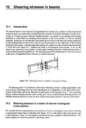
3.3.0 Suggested Beam Framing Details<br />
(By permission of the American Institute of <strong>Steel</strong> Construction, Chicago, Illinois.)
<strong>Structural</strong> <strong>Steel</strong>, <strong>Joists</strong>, <strong>and</strong> <strong>Metal</strong> <strong>Decking</strong> 157<br />
3.3.1 Suggested Column Base Plate Details<br />
(By permission of the American Institute of <strong>Steel</strong> Construction, Chicago, Illinois.)
158 Section 3<br />
3.3.2 Suggested <strong>Structural</strong> <strong>Steel</strong> Erection Details—Miscellaneous<br />
(By permission from The McGraw-Hill Co., <strong>Structural</strong> Details Manual, David R. Williams.)
<strong>Structural</strong> <strong>Steel</strong>, <strong>Joists</strong>, <strong>and</strong> <strong>Metal</strong> <strong>Decking</strong> 159<br />
3.3.4 Typical Braced Bay—Detail Connections<br />
(By permission from The McGraw-Hill Co., <strong>Structural</strong> Details Manual, David R. Williams.)
160 Section 3<br />
3.3.5 Typical Braced Bay—Other Detail Connections<br />
(By permission from The McGraw-Hill Co., <strong>Structural</strong> Details Manual, David R. Williams.)
3.3.6 Typical Channel Girt Connection<br />
(By permission from The McGraw-Hill Co., <strong>Structural</strong> Details Manual, David R. Williams.)<br />
161
162 Section 3<br />
Figure 3.3.7<br />
Typical Roof Opening Detail<br />
(By permission from The McGraw-Hill Co., <strong>Structural</strong> Details Manual, David R. Williams.)
<strong>Structural</strong> <strong>Steel</strong>, <strong>Joists</strong>, <strong>and</strong> <strong>Metal</strong> <strong>Decking</strong> 163<br />
3.3.8 Typical LH–Joist Connection Details<br />
(By permission from The McGraw-Hill Co., <strong>Structural</strong> Details Manual, David R. Williams.)
164 Section 3<br />
3.3.9 Beam Moment Connection Detail<br />
(By permission from The McGraw-Hill Co., <strong>Structural</strong> Details Manual, David R. Williams.)
<strong>Structural</strong> <strong>Steel</strong>, <strong>Joists</strong>, <strong>and</strong> <strong>Metal</strong> <strong>Decking</strong> 165<br />
3.4.0 Welded Joints—St<strong>and</strong>ard Symbols<br />
(By permission of the American Institute of <strong>Steel</strong> Construction, Chicago, Illinois.)
166 Section 3<br />
3.4.1 Tensile Strength of Puddle Welds<br />
(By permission from <strong>Steel</strong> Deck Institute, Fox River Grove, Illinois.)
<strong>Structural</strong> <strong>Steel</strong>, <strong>Joists</strong>, <strong>and</strong> <strong>Metal</strong> <strong>Decking</strong> 167<br />
3.5.0 Threaded Fasteners—Bolt Head Shapes<br />
(By permission of the American Institute of <strong>Steel</strong> Construction, Chicago, Illinois.)
168 Section 3<br />
3.5.1 Threaded Fasteners—Weight of Bolts<br />
(By permission of the American Institute of <strong>Steel</strong> Construction, Chicago, Illinois.)
<strong>Structural</strong> <strong>Steel</strong>, <strong>Joists</strong>, <strong>and</strong> <strong>Metal</strong> <strong>Decking</strong> 169<br />
3.5.2 Threaded Fasteners—Weight of ASTM A325 or A490 Bolts<br />
(By permission of the American Institute of <strong>Steel</strong> Construction, Chicago, Illinois.)
170 Section 3<br />
Heavy Hex <strong>Structural</strong> Bolts with Heavy Hex Nuts in Pounds per 100<br />
(By permission of Nucor Fastener division of Nucor Corp., St. Joe, Indiana.)
<strong>Structural</strong> <strong>Steel</strong>, <strong>Joists</strong>, <strong>and</strong> <strong>Metal</strong> <strong>Decking</strong> 171<br />
3.5.3 Properties of Heavy Hex Nuts <strong>and</strong> Identifying Marks<br />
(By permission of Nucor Fastener division of Nucor Corp., St. Joe, Indiana.)
172 Section 3<br />
3.5.4 Bolt Diameters <strong>and</strong> St<strong>and</strong>ard Hole Dimensions<br />
(By permission of Nucor Fastener division of Nucor Corp., St. Joe, Indiana.)
<strong>Structural</strong> <strong>Steel</strong>, <strong>Joists</strong>, <strong>and</strong> <strong>Metal</strong> <strong>Decking</strong> 173<br />
3.5.5 Capscrews/Bolts/Heavy Hex Nut Identifying Marks<br />
(By permission of Nucor Fastener division of Nucor Corp., St. Joe, Indiana.)
3.5.6 Dimensions of Finished Hex Nuts<br />
(By permission of Nucor Fastener division of Nucor Corp., St. Joe, Indiana.)<br />
174
<strong>Structural</strong> <strong>Steel</strong>, <strong>Joists</strong>, <strong>and</strong> <strong>Metal</strong> <strong>Decking</strong> 175<br />
3.5.7 Dimensions of Finished Hex Bolts<br />
3.5.8 Tension Control (TC) Bolt Installation Procedures<br />
Tru-Tension Fasteners are designed to be installed with various types of lightweight portable electric<br />
wrenches specifically intended for use with this style of structural fastener. They can be utilized for<br />
any applications where A325 <strong>and</strong> A490 bolts are specified. The installation tool has an inner socket,<br />
which engages the spline tip of the bolt spline, <strong>and</strong> when the tension is sufficient in the fastener, the<br />
spline tip simply twists off, leaving the tightened bolt correctly installed in the connection.<br />
(By permission of Nucor Fastener division of Nucor Corp., St. Joe, Indiana.)
176 Section 3<br />
3.5.9 Tru-Tension (TC) Bolt Assembly Specifications<br />
(By permission of Nucor Fastener division of Nucor Corp., St. Joe, Indiana.)