Bladder Accumulators.qx - Airline Hydraulics
Bladder Accumulators.qx - Airline Hydraulics
Bladder Accumulators.qx - Airline Hydraulics

Create successful ePaper yourself
Turn your PDF publications into a flip-book with our unique Google optimized e-Paper software.
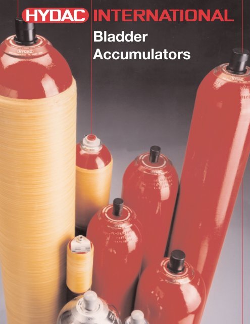
<strong>Bladder</strong><br />
<strong>Accumulators</strong>
HYDAC<br />
<strong>Bladder</strong><br />
<strong>Accumulators</strong><br />
Index<br />
Page<br />
1. Description 3<br />
Introduction 3<br />
Construction 3<br />
2. Applications 4<br />
3. Technical Data 6<br />
Operation 6<br />
Technical Specifications 6<br />
Temperature Effect 6<br />
Formulas for Sizing <strong>Accumulators</strong> 7<br />
Sizing Example 7<br />
4. Installation Requirements 8<br />
5. Model Code 9<br />
6. Bottom Repairable Specifications 10<br />
7. Top Repairable and High Flow Specifications 12<br />
8. Special <strong>Bladder</strong> <strong>Accumulators</strong> 14<br />
2
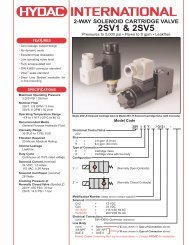
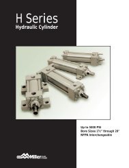
1. DESCRIPTION<br />
CONSTRUCTION<br />
Corrosion Protection<br />
INTRODUCTION<br />
Fluids are practically incompressible<br />
and cannot therefore store pressure<br />
energy.<br />
The compressibility of a gas<br />
(nitrogen) is utilized in hydropneumatic<br />
accumulators for storing<br />
fluids. HYDAC bladder<br />
accumulators are designed on this<br />
principle, using nitrogen as the<br />
compressible medium.<br />
The bladder accumulator consists<br />
of a fluid section and a gas section,<br />
with the bladder acting as a gasproof<br />
screen. The fluid around the<br />
bladder is connected with the<br />
hydraulic circuit, so that the bladder<br />
accumulator draws in fluid when the<br />
pressure increases thus<br />
compressing the gas. When the<br />
pressure drops, the compressed<br />
gas expands and forces the stored<br />
fluid into the circuit.<br />
Gas Valve Core<br />
Lock Nut<br />
Shell<br />
<strong>Bladder</strong><br />
Anti-<br />
Extrusion<br />
Ring<br />
Lock Nut<br />
Valve Seal Cap<br />
Valve Protection<br />
O-Ring Cap<br />
Name Plate<br />
Fluid Port<br />
Seal Ring<br />
Vent Screw<br />
HYDAC offers internal and/or<br />
external protective coatings. If this is<br />
insufficient, stainless steel is also<br />
available.<br />
Mounting Position<br />
HYDAC bladder accumulators can<br />
by installed vertically, horizontally or<br />
even at an angle. When installing<br />
vertically or at an angle, the fluid port<br />
must be at the bottom. On certain<br />
applications listed below, particular<br />
positions are preferable:<br />
• energy storage: vertical<br />
• pulsation damping: any position<br />
form horizontal to vertical<br />
• maintaining constant pressure:<br />
any position from horizontal to<br />
vertical<br />
• volume compensation: any<br />
position from horizontal to<br />
vertical<br />
System Mounting<br />
HYDAC bladder accumulators<br />
consist of a welded or forged<br />
pressure vessel (shell), a bladder and<br />
ports for gas and fluid inlet. The gas<br />
and fluid sides are separated by the<br />
bladder.<br />
HYDAC bladder accumulators are<br />
designed to be screwed directly onto<br />
the system. We also recommend the<br />
use of our mounting components,<br />
refer to Mounting Components<br />
brochure # A 3.502, to minimize risk<br />
of failure due to system vibrations.<br />
<strong>Bladder</strong> Materials<br />
Not all fluids are compatible with<br />
every elastomer at all temperatures.<br />
Therefore, HYDAC offers the<br />
following choice of elastomers:<br />
• NBR (Standard Nitrile)<br />
• LT-NBR (Low Temperature Nitrile)<br />
• ECO (Epichlorohydrin)<br />
• IIR (Butyl)<br />
• FPM (Fluorelastomer)<br />
• others available upon request.<br />
3
2. APPLICATIONS<br />
TYPICAL APPLICATIONS<br />
HYDAC bladder accumulators can<br />
be used in a wide variety of<br />
applications some of which are listed<br />
below:<br />
• energy storage<br />
• emergency operation<br />
• force equilibrium<br />
• leakage compensation<br />
• volume compensation<br />
• shock absorption<br />
• vehicle suspension<br />
• pulsation dampening<br />
1 bladder accumulator SB 600 - 32 with backup<br />
nitrogen bottle<br />
Crude oil piston pump<br />
A HYDAC bladder accumulator with<br />
back-up nitrogen bottle supplies<br />
fluid to a hydrostatic secondary<br />
control motor. The motor in turn<br />
drives the piston pump rod through<br />
its acceleration profile on its upward<br />
stroke.<br />
2 bladder accumulators SB 330 - 54<br />
Plastic injection molding machine<br />
Typically, the flow demand during a<br />
cycle varies greatly (see fig. 1). By<br />
utilizing HYDAC bladder<br />
accumulators, pump size can be<br />
reduced, thus saving energy while<br />
improving cycle rate.<br />
Q<br />
100%<br />
50%<br />
Maximum<br />
Average<br />
10 High flow bladder accumulators SB 290 HF<br />
100 - 70<br />
Hydropuls ® - resonance fatigue<br />
testing machine (Carl Schenck AG)<br />
This fatigue-testing machine is used<br />
to establish metallurgical limits.<br />
HYDAC high flow bladder<br />
accumulators provide fluid volume<br />
over a relatively low pressure range<br />
for cycling at a frequency of 30 Hz.<br />
This ensures uniform loading on the<br />
test sample.<br />
Cycle period<br />
t<br />
figure 1<br />
4
Putzmeister ® Concrete Pumper<br />
The HYDAC bladder accumulator<br />
provides flow to the cylinder<br />
switching circuit.<br />
1 bladder accumulator SB 330-4<br />
Coal Crusher<br />
The coal is crushed hydraulically by<br />
hammers in a rotary motion. The<br />
hammers have a tendency to<br />
oscillate up and down due to the<br />
unevenness of the coal being fed<br />
into the crushing bed.<br />
HYDAC bladder accumulators are<br />
installed to prevent pressure shocks<br />
and reduce the oscillations of the<br />
hammers; the accumulators provide<br />
hydro-pneumatic suspension.<br />
3 bladder accumulator SB 330-20<br />
Loading Fuel Tankers<br />
Any sudden change in the steady<br />
state condition of flow (e.g. when the<br />
shut-off valve is closed at the end of a<br />
long pipeline) causes an increase in<br />
pressure which may be many times<br />
that of the normal working pressure.<br />
When installed near the shut-off<br />
valve, HYDAC bladder accumulators<br />
absorb the motion energy of the<br />
fluid, allowing the pressure to rise<br />
slowly to a permissible level.<br />
Pipelines and valves are therefore<br />
protected from pressure surges.<br />
2 high flow bladder accumulators SB 35 HF 140-32<br />
5
3. TECHNICAL DATA<br />
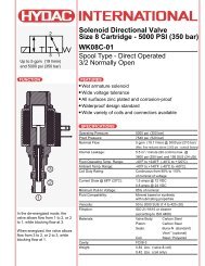
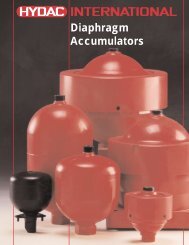
OPERATION<br />
Describing the operation of bladder<br />
accumulators:<br />
1 The bladder is precharged with<br />
nitrogen. This causes the fluid<br />
valve to close, preventing the<br />
bladder from extruding out of the<br />
fluid port.<br />
2 Accumulator at maximum<br />
working pressure. The difference<br />
in volume (∆V) between the<br />
maximum and the minimum<br />
working pressure corresponds to<br />
the effective fluid volume.<br />
3 When the minimum working<br />
pressure is reached, a small<br />
amount of fluid should remain in<br />
the accumulator. This is to<br />
prevent the bladder from chafing<br />
the valve on each cycle. Thus, p 0<br />
should always be lower than p 1 .<br />
P0<br />
V0<br />
1<br />
∆V = V1 - V2<br />
P2<br />
V2<br />
p 0 = gas precharge<br />
p 1 = minimum working pressure<br />
p 2 = maximum working pressure<br />
V 0 = effective gas volume of<br />
the accumulator<br />
2<br />
V 1 = gas volume at p 1<br />
V 2 = gas volume at p 2<br />
P1<br />
V1<br />
3<br />
∆V<br />
TECHNICAL<br />
SPECIFICATION<br />
Maximum working pressure<br />
Please refer to tables on pages 10,<br />
12 and 14.<br />
In other countries the maximum<br />
working pressure may be different.<br />
Maximum allowable pressure<br />
ration<br />
Ration of maximum working<br />
pressure (P 2 ) to gas precharge<br />
pressure (p 0 ).<br />
p 2 : p 0 ≤ 4 :1<br />
Nominal volume (size)<br />
Please refer to tables on pages 10,<br />
12 and 14.<br />
Effective gas volume (V 0 )<br />
Please refer to the tables on pages<br />
10, 12 and 14.<br />
Effective fluid volume (∆V)<br />
Volume of fluid available between<br />
the working pressures p 2 and p 1 .<br />
Fluids<br />
Mineral oil, hydraulic oil, water, water<br />
glycol and water emulsions. For<br />
other fluids, please contact HYDAC.<br />
Operating temperature range<br />
Selection of the shell material and<br />
elastomer depends on the operating<br />
temperature range of the unit. For<br />
selection, please refer to pages 8<br />
and 9.<br />
Flow rates<br />
The maximum allowable flow rate<br />
depends on the accumulator size.<br />
For selection, please refer to pages<br />
10 and 12.<br />
Recommended Gas Precharge<br />
Pressure<br />
• for energy storage:<br />
p 0 = 0.9 x p 1<br />
p 1 = minimum working pressure<br />
• for shock absorption:<br />
p 0 = (0.6 to 0.9) x p m<br />
p m = median working pressure at<br />
free flow<br />
• for pulsation dampening:<br />
p 0 = (0.6 to 0.8) x p m<br />
p m = median working pressure<br />
TEMPERATURE EFFECT<br />
To ensure that the recommended gas<br />
precharge pressure is maintained,<br />
even at relatively low or high<br />
operating temperatures, the gas<br />
precharge pressure should be<br />
adjusted for temperature. The<br />
formula below relates the precharge<br />
temperature (T 0 ) to the operating<br />
temperature (T). Please refer to the<br />
sizing example on page 7.<br />
Fahrenheit<br />
p 0 ,T 0<br />
= p0 ,T 2<br />
x (<br />
T0 + 460 ) T2 + 460<br />
T 0 = precharge temperature in °F<br />
T 2<br />
= maximum operating<br />
temperature in °F<br />
p 0 ,T 0 = gas precharge pressure at<br />
precharge temperature<br />
p 0 ,T 2 = gas precharge pressure at<br />
maximum operating<br />
pressure<br />
Celsius<br />
p 0 ,T 0<br />
= p0 ,T 2<br />
x (<br />
T0 + 273 ) T2 + 273<br />
6<br />
T 0 = temperature at precharging<br />
T 1 = minimum operating temperature<br />
T 2 = maximum operating temperature<br />
T 0 = precharge temperature in °C<br />
T 2<br />
= maximum operating<br />
temperature in °C<br />
p 0 ,T 0 = gas precharge pressure at<br />
precharge temperature<br />
p 0 ,T 2 = gas precharge pressure at<br />
maximum operating<br />
temperature
FORMULAS FOR SIZING<br />
ACCUMULATORS<br />
The compression and expansion<br />
processes taking place in<br />
hydropneumatic accumulator are<br />
governed by the general gas laws.<br />
The following applies for ideal gases:<br />
p 0 x V n 0 = p 1 x V n 1 = p 2 x V n 2 ,<br />
where the time related change of state<br />
is represented by the polytropic<br />
exponent “n”. For slow expansion and<br />
compression processes which occur<br />
almost isothermically, the polytropic<br />
exponent can be set at n = 1.<br />
For rapid processes, the adiabetic<br />
change of state can be calculated<br />
using n = k = 1.4 (for nitrogen as a<br />
diatomic gas) (1 .<br />
For pressures above 3000 psi the real<br />
gas behavior deviates considerably<br />
from the ideal one, which reduces the<br />
effective fluid volume ∆V. In such<br />
cases a correction is made which<br />
takes into account a change in the<br />
adiabatic exponent (k).<br />
By using the following formulas, the<br />
required gas volume V 0 can be<br />
calculated for various calculations.<br />
Low pressures of up to 150 psi must<br />
always be used as absolute pressures<br />
in the formulas.<br />
Calculation Formulas ∆V<br />
V0<br />
polytropic:<br />
=<br />
isothermal:<br />
(n=1)<br />
adiabatic:<br />
(n = k = 1.4)<br />
V0 =<br />
P0<br />
P1<br />
V0 =<br />
( ) ( )<br />
P0<br />
P1<br />
∆V<br />
( ) ( )<br />
1/n 1/n<br />
P0<br />
P2<br />
P0<br />
P2<br />
∆V<br />
( ) ( )<br />
P0<br />
P1<br />
0.714<br />
P0<br />
0.714<br />
P2<br />
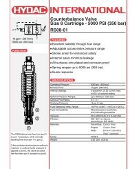
Correction factors to take into<br />
account the real gas behavior (2<br />
For isothermal change of condition:<br />
V 0,real = C i x V 0,ideal or<br />
∆V 0,real = ∆ V ideal<br />
C i<br />
for adiabatic change of condition:<br />
V 0,real = C a x V 0,ideal or<br />
∆V real = ∆ V ideal<br />
C a<br />
1 An estimate of the accumulator size and a selection of<br />
precharge pressure can be calculated similar to the<br />
sample shown. For more accurate sizing and design<br />
assistance, please contact HYDAC.<br />
2 The correction factors can be taken from the graphs in<br />
the next column, depending on the pressure ratio p 2 /p<br />
and the maximum working pressure p 1<br />
2 , which is given<br />
as a parameter, for an isothermal or adiabatic<br />
change of condition.<br />
correction factor Ci<br />
correction factor Ca<br />
Correction factor for isothermal<br />
change of condition<br />
1.7<br />
1.6<br />
1.5<br />
1.4<br />
1.3<br />
1.2<br />
1.1<br />
1.0<br />
1<br />
max working pressure p2 = 400 bar (5800 psi)<br />
300 bar (4350 psi)<br />
200 bar (2900 psi)<br />
SIZING EXAMPLE<br />
2 3 4 5<br />
pressure ratio p 2 /p 1<br />
Correction factor for adiabatic<br />
change of condition<br />
1.7<br />
1.6<br />
1.5<br />
1.4<br />
1.3<br />
1.2<br />
1.1<br />
1.0<br />
1<br />
max working pressure p2 = 400 bar (5800 psi)<br />
300 bar (4350 psi)<br />
200 bar (2900 psi)<br />
2 3 4 5<br />
pressure ratio p 2 /p 1<br />
An additional operation is to be<br />
added to an existing machine which<br />
requires 1.35 gallons of oil in 2.5<br />
seconds for optimal operation. The<br />
system must operate between 3000<br />
psi and 1500 psi. The required<br />
recharge time is 8 seconds with an<br />
operating temperature range of 75 to<br />
120°F.<br />
Given:<br />
maximum working pressure<br />
p 2 = 3000 psi<br />
minimum working pressure<br />
p 1 = 1500 psi<br />
effective fluid volume<br />
∆V = 1.35 gallons<br />
maximum operating temperature<br />
T 2 = 120°F<br />
minimum operating temperature<br />
T 1 = 75°F<br />
Required:<br />
1. necessary accumulator size,<br />
taking into account the real gas<br />
behavior<br />
2. gas precharge pressure p 0 at<br />
68°F (T 0 )<br />
3. select accumulator size and type<br />
Solution:<br />
Since it is a rapid process, the<br />
change of condition of the gas can<br />
be assumed to be adiabatic.<br />
1. Determination of required gas<br />
volume:<br />
a) gas precharge pressure at T 2 :<br />
p 0 ,T 2 = 0.9 x p 1<br />
= 0.9 x 1500 = 1350 psi<br />
b) gas precharge pressure at T 1 :<br />
T<br />
p 0 = p 0 ,T 2 x 1 + 460<br />
(<br />
T 2 + 460<br />
)<br />
= 1350 psi x<br />
75 + 460<br />
( )<br />
120 + 460<br />
≈ 1245 psi<br />
c) ideal gas volume:<br />
V 0 ideal =<br />
=<br />
P0, (T1)<br />
P1<br />
= 3.95 gallons<br />
d) correction factor from diagram:<br />
p 2<br />
= 2 - Ca ≈ 1.16<br />
p 1<br />
e) real gas volume:<br />
V 0, real = C a x V 0, ideal<br />
= 1.16 x 3.95<br />
= 4.6 gal.<br />
2. Determination of gas precharge<br />
pressure p 0 at 68°F:<br />
p 0 , T 0 = p 0 , T 2 x<br />
= 1350 psi x<br />
≈ 1230 psi<br />
∆V<br />
( ) ( )<br />
1245<br />
1500<br />
0.714<br />
P0, (T1)<br />
0.714<br />
P2<br />
1.35<br />
( ) ( )<br />
0.714 0.714<br />
1245<br />
3000<br />
T0 + ( T2 + 460)<br />
( )<br />
68 + 460<br />
120 + 460<br />
3. Selected: Size 20 (5 gallon)<br />
Model: SB 330 -20A1 / 112S - 210C<br />
Precharged to 1230 psi at 68°F<br />
7
4. INSTALLATION<br />
REQUIREMENTS<br />
General Suggestions<br />
WARNING!<br />
Hydraulic accumulators are<br />
pressurized vessels and only<br />
qualified technicians should perform<br />
repairs. Never weld, braze or<br />
perform any type of mechanical<br />
work on the accumulator shell.<br />
When handling an accumulator<br />
never lift it by the gas valve.<br />
Always drain the fluid completely<br />
from the accumulator before<br />
performing any work, such as<br />
recommended repairs (see<br />
Maintenance Instructions) or<br />
connecting pressure gauges.<br />
Precharge new or repaired<br />
accumulators with dry nitrogen to<br />
the proper gas precharge pressure<br />
(p 0 ).<br />
For more complete details, please<br />
refer to HYDAC Operating and<br />
Installation Instructions.<br />
HYDAC suggests a thorough<br />
inspection including a pressure test<br />
every 5 to 10 years depending upon<br />
the application.<br />
Country of Installation<br />
Pressure vessel codes vary<br />
depending upon the country of<br />
installation. In the United States<br />
and Canada pressure vessels are<br />
governed by the ASME pressure<br />
vessel code. HYDAC manufactures<br />
according to these standards.<br />
For installations in countries outside<br />
of the United States, please consult<br />
HYDAC for the appropriate<br />
certifications*. The country of<br />
installation codes shown below are<br />
required for ordering: please refer to<br />
page 9.<br />
Argentina<br />
S<br />
Australia<br />
F<br />
Austria<br />
D<br />
Brazil<br />
K<br />
Canada<br />
S/S1<br />
Chile<br />
S<br />
China<br />
A9<br />
Finland<br />
L<br />
France<br />
B<br />
Germany<br />
A<br />
Great Britain (UK)<br />
K<br />
Italy<br />
M<br />
Japan<br />
P<br />
Mexico<br />
E<br />
Russia<br />
A6<br />
Sweden<br />
R<br />
USA<br />
S<br />
others upon request<br />
!<br />
CAUTION<br />
Elastomer Compatibility Table<br />
In order to maximize system performance it is important to match your<br />
system fluid and its temperature range with the appropriate elastomer<br />
compound. The table below illustrates the most common ones. For special<br />
requirements, please consult HYDAC.<br />
Operating<br />
Some<br />
Compound Temperature Typical<br />
Range<br />
Fluids<br />
NBR (BUNA N)<br />
5°F to 180°F mineral oils<br />
32°F to 180°F water and water-glycols<br />
LT-NBR (low temp. NBR) -40°F to 180°F mineral oils<br />
ECO (HYDRIN) -20°F to 250°F mineral oils<br />
IIR (BUTYL) -20°F to 200°F<br />
FPM (VITON) 5°F to 300°F<br />
Gas Charging<br />
Pressurized Vessel –<br />
Use Dry Nitrogen Gas Only!<br />
phosphate esters<br />
brake fluids<br />
chlorinated<br />
hydrocarbons<br />
Notes:<br />
1. The operating temperature range does vary with fluid types, please consult<br />
HYDAC for more specific fluid data.<br />
2. The above typical fluids are some examples of the most common fluids, please<br />
consult HYDAC for specific data.<br />
3. For temperatures below - 40°F and above 200°F, please consult HYDAC for<br />
maximum allowable working pressures of the pressure vessels.<br />
4. For other applications not listed, please consult HYDAC.<br />
8<br />
* The European Community (EC) has the Pressure Equipment Directive (PED) that is<br />
being phased in. Contact HYDAC for details.
5. Model Code: <strong>Bladder</strong> <strong>Accumulators</strong><br />
Series<br />
SB 330 - 3000 psi<br />
SB 600 - 5000 psi<br />
Special design (if required)<br />
H = High Flow<br />
T = Top Repairable<br />
HT = High Flow / Top Repairable<br />
Size (see tables)<br />
Line Connection<br />
A = Threaded<br />
F = Flanged<br />
Gas port<br />
1 = Standard model, HYDAC gas valve version 4 (8V1 - ISO 4570)<br />
2 = Transfer barrier model<br />
Material Code<br />
Depending on application<br />
112 = Standard for oil service (mineral oil)<br />
Fluid port<br />
0 Synthetic coated carbon steel (internal & external for water service)<br />
1 Carbon steel<br />
2 Stainless steel (304)<br />
3 Stainless steel (316)<br />
4 Chemically plated carbon steel (internal & external for water service)<br />
6 Low temperature carbon steel (
6. Standard <strong>Bladder</strong> <strong>Accumulators</strong> Bottom Reparaible:<br />
SB 330 / SB 600 (3000 / 5000 psi)<br />
SB 330 (maximum working pressure 3000 psi)<br />
size<br />
nom.<br />
vol.<br />
gal<br />
1 1/4 66<br />
eff. weight A<br />
gas lbs max<br />
vol max in<br />
in 3 (kg) (mm)<br />
B 1 C ØD ØE<br />
in in max in<br />
(mm) (mm) (mm) (mm)<br />
10 12.0 2.0 2.3 4.6 1.4 1 1/16-12<br />
(4.5) (303) (51) (58) (117) (36) UN<br />
thread Q 2<br />
SAE NPTF gpm<br />
3/4” 60<br />
4 1 226<br />
6 1 1/2 340<br />
10 2 1/2 566<br />
20 5 1125<br />
32 10 2080<br />
54 15 3205<br />
30 16.3 2.6 2.3 6.6 2.1 1 5/8-12 1 1/4” 160<br />
(14) (415) (66) (58) (168) (53) UN<br />
33 20.5 2.6 2.3 6.6 2.1 1 5/8-12 1 1/4” 160<br />
(15) (521) (66) (58) (168) (53) UN<br />
86 22.0 3.1 2.3 9.1 3.0 1 7/8-12<br />
(39) (559) (80) (58) (231) (76) UN<br />
140 34.5 3.1 2.3 9.1 3.0 1 7/8-12<br />
(63) (876) (80) (58) (231) (76) UN<br />
226 54.7 3.1 2.3 9.1 3.0 1 7/8-12<br />
(102) (1390) (80) (58) (231) (76) UN<br />
330 78.3 3.1 2.3 9.1 3.0 1 7/8-12<br />
(150) (1990) (80) (58) (231) (76) UN<br />
2” 240<br />
2” 240<br />
2” 240<br />
2” 240<br />
SB 600 (maximum working pressure 5000 psi)<br />
size<br />
eff. weight A<br />
nom.<br />
B 1 gas lbs max<br />
C ØD ØE<br />
thread Q 2<br />
vol.<br />
vol max in<br />
in in max in<br />
SAE NPTF gpm<br />
gal<br />
in 3 (kg) (mm)<br />
(mm) (mm) (mm) (mm)<br />
1 1/4 66<br />
17 13.2 2.4 2.3 4.8 2.1 1 5/8-12<br />
(7.7) (335) (62) (58) (122) (53) UN<br />
N/A 60<br />
4 1 226<br />
33 16.3 2.5 2.3 6.8 2.1 1 5/8-12<br />
(15) (414) (64) (58) (173) (53) UN<br />
N/A 160<br />
10 2 1/2 566<br />
114 22.4 3.1 2.8 9.1 3.0 1 7/8-12<br />
(52) (568) (80) (70) (231) (76) UN<br />
N/A 240<br />
20 5 1125<br />
162 35.0 3.1 2.8 9.1 3.0 1 7/8-12<br />
(73) (888) (80) (70) (231) (76) UN<br />
N/A 240<br />
32 10 2080<br />
250 55.2 3.1 2.8 9.1 3.0 1 7/8-12<br />
(113) (1402) (80) (70) (231) (76) UN<br />
N/A 240<br />
54 15 3180<br />
370 78.8 3.1 2.8 9.1 3.0 1 7/8-12<br />
(168) (2002) (80) (70) (231) (76) UN<br />
N/A 240<br />
1) For SAE thread only<br />
2) Maximum discharge flow rate recommended for vertically mounted accumulators<br />
Split Flange Connection (optional): Split Flange Connection (size 10 to 54)<br />
series<br />
B<br />
øE<br />
in in<br />
Connection Q 2<br />
(mm)<br />
(mm)<br />
F<br />
gpm<br />
SB 330 4.1 2.8 SAE 2”-3000 psi<br />
SB 330T 3 (104) (71.4) (code 61)<br />
240<br />
SB 600 5.5 2.5 SAE 1 1/2”-6000 psi<br />
240<br />
SB 600T 3 (140) (63.5) (code 62)<br />
3) size 20 to 54 only<br />
10
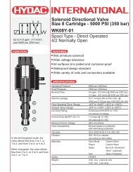
Spare Parts: <strong>Accumulators</strong> SB 330, SB 330 H, and SB 660<br />
3<br />
4<br />
1<br />
2<br />
Detail Z<br />
6<br />
8<br />
Item<br />
Description:<br />
1 Shell<br />
2 <strong>Bladder</strong><br />
3 Gas Valve Core<br />
4 Lock Nut<br />
5 Valve Seal Cap<br />
6 Valve Protection Cap<br />
7 O-ring<br />
8 Name Plate<br />
9 Fluid Port<br />
14 Anti-extrusion Ring<br />
15 Flat Ring<br />
16 O-ring<br />
17 Spacer Ring<br />
18 Lock Nut<br />
19 Vent Screw<br />
20 Seal Ring<br />
23 Back-up Ring<br />
14<br />
Detail X<br />
18<br />
9<br />
17<br />
20<br />
19<br />
Repair Kit Consists Of:<br />
2 <strong>Bladder</strong><br />
3 Gas Valve Core<br />
4 Fluid Port Lock Nut<br />
(SB 600 only)<br />
5 Valve Seal Cap<br />
7 O-Ring<br />
15 Flat Ring<br />
16 O-Ring<br />
23 Back-up Ring<br />
(where applicable)<br />
Seal Kit Consists Of:<br />
15 Flat Ring<br />
16 O-Ring<br />
23 Back-up Ring<br />
(where applicable)<br />
Detail X<br />
SB 330: size 1 to 54 SB 330H: size 10<br />
SB 660: size 1 to 4 SB 600: size 10 to 54<br />
Detail Z<br />
15<br />
16<br />
17<br />
15<br />
16<br />
23<br />
17<br />
5<br />
3<br />
7<br />
11
7. Top Repairable and High Flow <strong>Bladder</strong> <strong>Accumulators</strong>:<br />
SB 330 T, SB 330 H, SB 330 HT (3000 psi), and SB 600 T (5000 psi)<br />
SB 330 T, SB 330 HT, SB 600 T<br />
SB 330 H<br />
M95x2<br />
SB 330 T (maximum working pressure 3000 psi) 1<br />
eff. weight A<br />
nom.<br />
B 2<br />
ØD<br />
gas lbs max<br />
C<br />
max<br />
ØE<br />
size vol.<br />
vol max in<br />
in in<br />
in<br />
in<br />
gal<br />
in 3 (kg) (mm)<br />
(mm) (mm)<br />
(mm)<br />
(mm)<br />
thread j<br />
Q 3<br />
SAE NPTF gpm<br />
10 2 1/2 566<br />
94 21 3.1 1.3 9.1 3.0 1 7/8-12<br />
(43) (533) (80) (33) (231) (76) UN<br />
2” 240<br />
20 5 1125<br />
148 33.5 3.1 1.3 9.1 3.0 1 7/8-12<br />
(67) (851) (80) (33) (231) (76) UN<br />
2” 240<br />
32 10 2080<br />
234 53.7 3.1 1.3 9.1 3.0 1 7/8-12<br />
(106) (1364) (80) (33) (231) (76) UN<br />
2” 240<br />
54 15 3205<br />
340 77.3 3.1 1.3 9.1 3.0 1 7/8-12<br />
(154) (1964) (80) (33) (231) (76) UN<br />
2” 240<br />
SB 330 HT (maximum working pressure 3000 psi) 1<br />
20 5 1125<br />
161 35.7 5.3 1.3 9.1 3.8 2 1/2-12<br />
(73) (907) (135) (33) (231) (97) UN<br />
32 10 2080<br />
247 56.9 5.3 1.3 9.1 3.8 2 1/2-12<br />
(112) (1420) (135) (33) (231) (97) UN<br />
54 15 3205<br />
352 79.5 5.3 1.3 9.1 3.8 2 1/2-12<br />
(160) (2020) (135) (33) (231) (97) UN<br />
SB 600 T (maximum working pressure 5000 psi) 1<br />
20 5 1125<br />
172 33.5 3.1 1.6 9.1 3.0 1 7/8-12<br />
(78) (851) (80) (40) (231) (76) UN<br />
32 10 2080<br />
260 53.7 3.1 1.6 9.1 3.0 1 7/8-12<br />
(118) (1364) (80) (40) (231) (76) UN<br />
54 15 3205<br />
380 77.3 3.1 1.6 9.1 3.0 1 7/8-12<br />
(172) (1964) (80) (40) (231) (76) UN<br />
N/A 480<br />
N/A 480<br />
N/A 480<br />
N/A 240<br />
N/A 240<br />
N/A 240<br />
12<br />
1) SAE split flange connections for SB 330 T see page 10.<br />
2) For SAE thread only.<br />
3) Maximum discharge flow rate recommended for vertically accumulators.
Spare Parts: SB 330 T, SB 330 HT, and SB 600 T<br />
22<br />
Detail Y<br />
1<br />
2<br />
24<br />
14<br />
Detail X<br />
18<br />
Seal Kit Consists of:<br />
4<br />
SB330T:<br />
15 Flat Ring<br />
16 O-ring<br />
28 Flat Ring<br />
29 O-ring<br />
30 Back-up Ring<br />
SB330HT:<br />
15 Flat Ring 1)<br />
16 O-ring 1)<br />
23 Back-up Ring 1)<br />
SB600T:<br />
15 Flat Ring 1)<br />
16 O-ring 1)<br />
23 Back-up Ring 1)<br />
Detail Z<br />
6<br />
9<br />
19<br />
20<br />
31<br />
Detail X<br />
SB 330 T: size 10 to 54<br />
15<br />
16<br />
17<br />
SB 330 HT: size 20 to 54<br />
SB 600 T: size 20 to 54<br />
15<br />
16<br />
23<br />
17<br />
Detail Y<br />
SB 330 T: size 10 to 54<br />
SB 330 HT: size 20 to 54<br />
6<br />
31<br />
30<br />
29<br />
28<br />
SB 600 T: size 20 to 54<br />
Detail Z<br />
6<br />
31<br />
17<br />
30<br />
29<br />
28<br />
5<br />
3<br />
7<br />
Item Description:<br />
1 Shell<br />
2 <strong>Bladder</strong><br />
3 Gas Valve Core<br />
4 Lock Nut<br />
5 Valve Seal Cap<br />
6 Valve Protection Cap<br />
7 O-ring<br />
Fluid Side<br />
9 Fluid Port<br />
14 Anti-extrusion Ring<br />
15 Flat Ring<br />
16 O-ring<br />
17 Spacer Ring<br />
18 Lock Nut<br />
19 Vent Screw<br />
20 Seal Ring<br />
23 Back-up Ring<br />
Gas Side<br />
22 Gas Port Adapter<br />
24 Anti-extrusion Ring<br />
28 Flat Ring<br />
29 O-ring<br />
30 Back-up Ring<br />
31 Lock Nut<br />
SB 330 T, SB 600 T<br />
Repair Kit consists of:<br />
2 <strong>Bladder</strong><br />
3 Gas Valve Core<br />
5 Valve Seal Cap<br />
7 O-ring<br />
15 Flat Ring<br />
16 O-ring<br />
28 Flat Ring<br />
29 O-ring<br />
30 Back-up Ring<br />
SB 330 HT<br />
Repair Kit consists of:<br />
2 <strong>Bladder</strong><br />
3 Gas Valve Core<br />
5 Valve Seal Cap<br />
7 O-ring<br />
28 Flat Ring<br />
29 O-ring<br />
30 Back-up Ring<br />
1) These parts can be used on either the gas<br />
side or the fluid side, if both sides are<br />
being re-sealed two kits are required.<br />
13
8. SPECIAL BLADDER<br />
ACCUMULATORS<br />
HIGH PRESSURE<br />
BLADDER<br />
ACCUMULATORS<br />
SB 800, SB 1000<br />
The HYDAC high pressure bladder<br />
accumulators work on the same<br />
principles as our standard bladder<br />
accumulators.<br />
HYDAC offers them in standard<br />
carbon or stainless steel.<br />
SB 800<br />
(maximum working pressure 11,600 psi)<br />
Size 1.5<br />
Gas Volume - in 3 90<br />
Weight - lbs (kg) 68.4 (31)<br />
Dimensions: SB 800<br />
LOW PRESSURE<br />
BLADDER<br />
ACCUMULATORS<br />
HYDAC offers low pressure bladder<br />
accumulators. Please consult<br />
HYDAC for details.<br />
STAINLESS STEEL<br />
BLADDER<br />
ACCUMULTORS<br />
HYDAC offers stainless steel<br />
bladder accumulators. Please<br />
consult HYDAC for details.<br />
SB 1000<br />
(maximum working pressure 14,500 psi)<br />
Size 1.5<br />
Gas Volume - in 3 90<br />
Weight - lbs (kg) 190 (86)<br />
Note: dimensions shown in mm.<br />
SB 1000<br />
Note: dimensions shown in mm.<br />
14
TRANSFER BARRIER<br />
TYPE BLADDER<br />
ACCUMULATORS<br />
SB 600: Size 20 to 54<br />
With a small differential between<br />
minimum and maximum working<br />
pressure, the nitrogen in the<br />
accumulator can only be<br />
compressed slightly. As a result the<br />
effective portion of accumulator<br />
volume is correspondingly small.<br />
When sizing so-called “back-up”<br />
type accumulators, the same<br />
principle is used as for individual<br />
accumulators, where V 0 represents<br />
the total volume of accumulator and<br />
nitrogen bottles.<br />
It should be noted, however, that<br />
on back-up accumulators, the<br />
accumulator should only be charged<br />
to 75 % of its fluid capacity to keep<br />
the bladder from being over<br />
compressed.<br />
The gas precharge pressure can be<br />
higher than 0.9 times the min.<br />
working pressure, so that when<br />
discharged to min. working pressure<br />
p 1 , a residual fluid volume ∆V R of<br />
approx. 10% of the accumulator<br />
volume remains.<br />
The calculation must be iterative.<br />
After each stage, check whether the<br />
effective volume (∆V’) is sufficient to<br />
take up the fluid volume during<br />
isothermal charging, from gas<br />
precharge pressure to working<br />
pressure.<br />
type 1<br />
type 2<br />
Checking the effective volume on a<br />
back-up version.<br />
∆V’ = V 0 (total)<br />
p 0<br />
- p 0<br />
( p 1 p 2 )<br />
∆V’ ≤ 0.75 x V 0 (accum.)<br />
Please consult HYDAC for more<br />
details.<br />
15
Other Products from HYDAC’s Accumulator Line<br />
Diaphragm <strong>Accumulators</strong><br />
Diaphragm accumulators are frequently used where small volumes are<br />
required, light weight is important, a higher pressure ratio is required (up to<br />
10:1), and low cost is a prime factor. Two styles are available weld (nonrepairable)<br />
and threaded (repairable). Both are suited for energy storage and<br />
shock applications.<br />
Nominal volume 5 in 3 to 1 gal.<br />
Max. working pressure 3000, 4700, and up to 10,000 psi<br />
Flow rate up to 40 gpm<br />
Piston <strong>Accumulators</strong><br />
A wide range of piston accumulators is available. Piston position monitoring is<br />
available using proximity switches, extending piston rod or ultrasonic<br />
techniques. Auxiliary gas bottles are frequently used with piston accumulators<br />
to provide the required gas volume.<br />
Nominal volume 1 qt. to 100 gal.<br />
Max. working pressure 3000, 5000, and up to 15000 psi<br />
Flow Rate up to 2000 gpm<br />
Request catalog # 02071831<br />
Request catalog # 02068597<br />
Mounting Components<br />
HYDAC mounting components are used to mount all types of hydropneumatic<br />
accumulators safely and simply, regardless of the mounting<br />
position. Our wide range includes suitable mounting components for every<br />
type. mounting components are used mainly for the following: to fix the<br />
accumulator into its position, to carry the weight of the accumulator, and to<br />
counteract the forces exerted by the hydraulic lines. HYDAC also offers base<br />
brackets for larger accumulators for proper support and isolation from system<br />
vibrations. The brackets incorporate a rubber support ring for this reason. All<br />
mounting components can be easily bolted to your system.<br />
Request catalog # 02071834<br />
Charging & Gauging<br />
To maintain system performance, HYDAC recommends a regular check of the<br />
gas precharge pressure. A loss in the gas precharge pressure will cause a<br />
drop in the system efficiency and could cause damage to the bladder,<br />
diaphragm or piston accumulator. By means of a charging and gauging unit,<br />
hydro-pneumatics accumulators are precharged with dry nitrogen or their<br />
existing gas precharge pressure is checked. For these purposes, a charging<br />
and gauging unit is connected to a commercially available nitrogen bottle via<br />
a flexible hose. The charging and gauging units incorporate a gauge, check<br />
valve in the charging connection, manual bleed valve and T-handle.<br />
Request catalog # 02071833<br />
© Copyright 2000 HYDAC TECHNOLOGY CORPORATION - Brochure - <strong>Bladder</strong> <strong>Accumulators</strong> #02071832 / 06.00<br />
HYDAC CORPORATION<br />
2280 City Line Road • Bethlehem, PA 18017<br />
Phone (610) 264-9503 • Fax (610) 264-7529<br />
www.hydacusa.com • powerup@hydacusa.com