Curved pipes - Powerpipe
Curved pipes - Powerpipe
Curved pipes - Powerpipe

You also want an ePaper? Increase the reach of your titles
YUMPU automatically turns print PDFs into web optimized ePapers that Google loves.
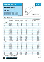
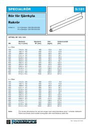
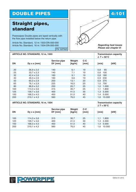
DOUBLE PIPES 4:101<br />
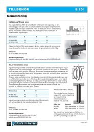
Straight <strong>pipes</strong>,<br />
standard<br />
Power<strong>pipes</strong> Double <strong>pipes</strong> are layed vertically with<br />
the flow pipe installed below the return pipe.<br />
Article No. Standard, 12 m: 1503-DN-000-000<br />
Article No. Standard, 16 m: 1504-DN-000-000<br />
PN 16/PN25<br />
Regarding heat losses<br />
Please see chapter 9!<br />
ARTICLE NO. STANDARD, 12 m, 1503<br />
Transmission capacity<br />
Δ T = 50°C<br />
Service pipe Weight C-C<br />
DN Dy x s [mm] DY [mm] [kg/m] [mm] [m/s] [kW]<br />
20 26,9 x 2,0 140 6,1 19 0,8 65<br />
25 33,7 x 2,3 140 7,1 19 0,8 100<br />
32 42,4 x 2,6 160 9,1 19 0,8 180<br />
40 48,3 x 2,6 160 9,6 19 0,9 230<br />
50 60,3 x 2,9 200 13,1 20 0,9 370<br />
65 76,1 x 2,9 225 16,5 20 1,0 700<br />
80 88,9 x 3,2 250 20,7 25 1,0 1.000<br />
100 114,3 x 3,6 315 30,7 25 1,1 1.800<br />
125 139,7 x 3,6 400 41,5 30 1,3 3.300<br />
150 168,3 x 4,0 450 51,0 40 1,4 5.000<br />
200 219,1 x 4,5 560 76,0 45 1,6 10.000<br />
ARTICLE NO. STANDARD, 16 m, 1504<br />
Transmission capacity<br />
Δ T = 50°C<br />
Service pipe Weight C-C<br />
DN Dy x s [mm] DY [mm] [kg/m] [mm] [m/s] [kW]<br />
100 114,3 x 3,6 315 30,7 25 1,1 1.800<br />
125 139,7 x 3,6 400 41,5 30 1,3 3.300<br />
150 168,3 x 4,0 450 51,0 40 1,4 5.000<br />
200 219,1 x 4,5 560 76,0 45 1,6 10.000<br />
Edition 01.2012
DOUBLE PIPES 4:102<br />
Straight <strong>pipes</strong>,<br />
double+<br />
Power<strong>pipes</strong> Double <strong>pipes</strong> are layed vertically with<br />
the flow pipe installed below the return pipe.<br />
Article No. Standard, 12 m: 1603-DN-000-000<br />
Article No. Standard, 16 m: 1604-DN-000-000<br />
PN 16/PN25<br />
Regarding heat losses<br />
Please see chapter 9!<br />
ARTICLE NO. DOUBLE+, 12 m, 1603<br />
Transmission capacity<br />
Δ T = 50°C<br />
Service pipe Weight C-C<br />
DN Dy x s [mm] DY [mm] [kg/m] [mm] [m/s] [kW]<br />
20 26,9 x 2,0 160 6,7 19 0,8 65<br />
25 33,7 x 2,3 160 7,8 19 0,8 100<br />
32 42,4 x 2,6 180 9,9 19 0,8 180<br />
40 48,3 x 2,6 180 10,3 19 0,9 230<br />
50 60,3 x 2,9 225 14,0 20 0,9 370<br />
65 76,1 x 2,9 250 17,6 20 1,0 700<br />
80 88,9 x 3,2 280 22,8 25 1,0 1.000<br />
100 114,3 x 3,6 355 33,9 25 1,1 1.800<br />
125 139,7 x 3,6 450 46,3 30 1,3 3.300<br />
150 168,3 x 4,0 500 56,5 40 1,4 5.000<br />
ARTICLE NO. DOUBLE+, 16 m, 1604<br />
Transmission capacity<br />
Δ T = 50°C<br />
Service pipe Weight C-C<br />
DN Dy x s [mm] DY [mm] [kg/m] [mm] [m/s] [kW]<br />
100 114,3 x 3,6 355 33,9 25 1,1 1.800<br />
125 139,7 x 3,6 450 46,3 30 1,3 3.300<br />
150 168,3 x 4,0 500 56,5 40 1,4 5.000<br />
Edition 01.2012
DOUBLE PIPES 4:103<br />
Straight <strong>pipes</strong>,<br />
double ++<br />
Power<strong>pipes</strong> Double <strong>pipes</strong> are layed vertically with<br />
the flow pipe installed below the return pipe.<br />
Article No. Standard, 12 m: 1703-DN-000-000<br />
Article No. Standard, 16 m: 1704-DN-000-000<br />
PN 16/PN25<br />
Regarding heat losses<br />
Please see chapter 9!<br />
ARTICLE NO. DOUBLE++, 12 m, 1703<br />
Transmission capacity<br />
Δ T = 50°C<br />
Service pipe Weight C-C<br />
DN Dy x s [mm] DY [mm] [kg/m] [mm] [m/s] [kW]<br />
20 26,9 x 2,0 180 7,4 19 0,8 65<br />
25 33,7 x 2,3 180 8,5 19 0,8 100<br />
32 42,4 x 2,6 200 10,6 19 0,8 180<br />
40 48,3 x 2,6 200 11,1 19 0,9 230<br />
50 60,3 x 2,9 250 15,1 20 0,9 370<br />
65 76,1 x 2,9 280 19,7 20 1,0 700<br />
80 88,9 x 3,2 315 24,9 25 1,0 1.000<br />
100 114,3 x 3,6 400 37,8 25 1,1 1.800<br />
125 139,7 x 3,6 500 51,8 30 1,3 3.300<br />
150 168,3 x 4,0 560 63,7 40 1,4 5.000<br />
ARTICLE NO. DOUBLE++, 16 m, 1704<br />
Transmission capacity<br />
Δ T = 50°C<br />
Service pipe Weight C-C<br />
DN Dy x s [mm] DY [mm] [kg/m] [mm] [m/s] [kW]<br />
100 114,3 x 3,6 400 37,8 25 1,1 1.800<br />
125 139,7 x 3,6 500 51,8 30 1,3 3.300<br />
150 168,3 x 4,0 560 63,7 40 1,4 5.000<br />
Edition 01.2012
DOUBLE PIPES 4:104<br />
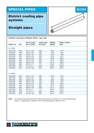
Straight <strong>pipes</strong> for<br />
cut-to-length<br />
PN 16/PN25<br />
Cut-to-lenght<br />
Kapzoner<br />
varannan meter<br />
sections are every<br />
second metre.<br />
Cut-to-length <strong>pipes</strong> are manufactured in all dimensions, as given in section 4:101. In these <strong>pipes</strong> the steel<br />
service pipe is covered by a plastic foil every second metre along the entire pipe length. This arrangement<br />
allows easy removal of the foam from the steel in the sections. These sections of the pipe are indicated on<br />
the outside casing pipe. Whole lengths or parts of <strong>pipes</strong> cut-to-lenght can be installed at any place in a district<br />
heating distribution system.<br />
ARTICLE NO. 1513, 1613, 1713 (12m)<br />
L = 12 m<br />
Article No..<br />
1513-DN-000-000 (STANDARD)<br />
1613-DN-000-000 (DOUBLE+)<br />
1713-DN-000-000 (DOUBLE++)<br />
For measurement details, please see<br />
straight <strong>pipes</strong>!<br />
Pipes are available with «center cut»<br />
Above should be indicated in a separate<br />
line of text.<br />
An example of how to order:<br />
Cut- to-length pipe Double pipe Standard DN 2*100,<br />
has Article No. 1513-100-000-000.<br />
Edition 01.2012
DOUBLE PIPES 4:105<br />
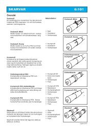
<strong>Curved</strong> <strong>pipes</strong><br />
Deflection<br />
PN 16/PN25<br />
ARTICLE NO. 1523, 1623, 1723 (12 m)<br />
ARTICLE NO. 1524, 1624, 1724 (16 m)<br />
Double pipe<br />
Max. deflection<br />
DN L = 12 m L= 16 m Anm.<br />
25 - 65 30° To be bent at installation site<br />
50 - 80 30° Bent at <strong>Powerpipe</strong> works<br />
100 30° 20° Bent at <strong>Powerpipe</strong> works<br />
125 - 150 30° 25° Bent at <strong>Powerpipe</strong> works<br />
200 25° 32° Bent at <strong>Powerpipe</strong> works<br />
Accuracy of manufacture DN 2*80 - 2*200 +/- 2°<br />
Steel service pipe<br />
In the manufacturing of curved <strong>pipes</strong> welded steel <strong>pipes</strong> are used.<br />
For manufacturing reasons alarm wires are placed in the neutral position.<br />
Article No..<br />
1523-DN-000-000 (STANDARD)<br />
1623-DN-000-000 (DOUBLE+)<br />
An example of how to order:<br />
<strong>Curved</strong> Double pipe L = 12m with dim DN 2*100, standard,<br />
has Article No. 1523-100-000-000.<br />
Deflection shall be stated in a separate line of text.<br />
Edition 01.2012
DOUBLE PIPES 4:106<br />
<strong>Curved</strong> <strong>pipes</strong><br />
Deflection versus<br />
design radius<br />
Design radius<br />
Length<br />
Deflection<br />
PN 16/PN25<br />
CORRELATION BETWEEN DEFLECTION AND DESIGN RADIUS<br />
Design radius<br />
Design radius<br />
Deflection L = 12 m Deflection L = 12 m<br />
1° 690 21° 33,0<br />
2° 345 22° 31,0<br />
3° 230 23° 30,0<br />
4° 170 24° 29,0<br />
5° 140 25° 28,0<br />
6° 115 26° 27,0<br />
7° 98 27° 26,0<br />
8° 86 28° 25,0<br />
9° 76 29° 24,0<br />
10° 69 30° 23,2<br />
11° 62 31° 22,5<br />
12° 57 32° 21,8<br />
13° 53 33° 21,1<br />
14° 49 34° 20,5<br />
15 o 46 35° 20,0<br />
16° 43 36° 19,4<br />
17° 40 37° 18,9<br />
18° 38 38° 18,4<br />
19° 36 39° 18,0<br />
20° 34 40° 17,5<br />
The <strong>pipes</strong> cannot be bent along its entire length. At each pipe end a straight part will remain,<br />
which shall be approximately 2 meters in lenght.<br />
This deviation from an ideal curved pipe radius is to be compensated when installing the pipe<br />
by making the pipe trench approximately wider at center.<br />
The widening should be ~200 mm at deviation < 10 o<br />
The widening should be ~500 mm at deviation > 10 o<br />
Edition 01.2012
DOUBLE PIPES 4:107<br />
<strong>Curved</strong> <strong>pipes</strong><br />
Elastic radius<br />
Design radius<br />
Length<br />
Deflection<br />
PN 16/PN25<br />
ELASTIC RADIUS<br />
Dimension Elastic radius Deflection/<br />
m<br />
12 m<br />
25 15 45°<br />
40 21 31°<br />
50 27 25°<br />
65 34 20°<br />
80 40 17°<br />
100 52 13°<br />
125 63 11°<br />
150 76 9°<br />
200 98 7°<br />
The above table shows the elastic radius which is the maximum radius or<br />
deflection that can be allowed without permanent deformation in the steel pipe.<br />
Edition 01.2012
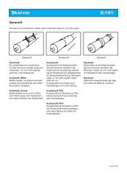
DOUBLE PIPES 4:201<br />
Bend<br />
PN 16/PN25<br />
ARTICLE NO. 2500, 2600, 2700<br />
STANDARD DOUBLE+ DOUBLE++<br />
2500 2600 2700<br />
Service pipe Jacket pipe Jacket pipe Jacket pipe L<br />
DN Dy x s [mm] DY [mm] DY [mm] DY [mm] [mm]<br />
20 26,9 x 2,0 140 160 180 1000<br />
25 33,7 x 2,3 140 160 180 1000<br />
32 42,4 x 2,6 160 180 200 1000<br />
40 48,3 x 2,6 160 180 200 1000<br />
50 60,3 x 2,9 200 225 250 1000<br />
65 76,1 x 2,9 225 250 280 1000<br />
80 88,9 x 3,2 250 280 315 1000<br />
100 114,3 x 3,6 315 355 400 1000<br />
125 139,7 x 3,6 400 450 500 1000<br />
150 168,3 x 4,0 450 500 560 1000<br />
200 219,1 x 4,5 560 1000<br />
Bends are, as standard, available as 90 o and 45 o .<br />
Bends having other degrees such as 75 o , 60 o , 30 o and 15 o and bends having leg lengths other than<br />
specified in the above table can be delivered on special request.<br />
Article No..<br />
2500-DN-degree of bend-000 (STANDARD)<br />
2600-DN-degree of bend-000 (DOUBLE+)<br />
2700-DN-degree of bend-000 (DOUBLE++)<br />
Space for sleeve<br />
In order to adequately fit sleeve<br />
Installation of DN2*50 –2*125 an<br />
Extended shank 1200 x 1200 mm<br />
is offered. State suffix: 999<br />
An example of how to order:<br />
Bend Double pipe Standard dim DN 2*80, 90°<br />
has Article No. 2500-080-090-000.<br />
Edition 01.2012
DOUBLE PIPES 4:202<br />
Termination bend, 90 o<br />
1500<br />
The termination bend is delivered with seal for<br />
the insulation at one pipe end. This seal prevent<br />
water from penetrating during the construction<br />
period. (regarding DN*25-65)<br />
The built-in alarmwires are linked utside the sealing.<br />
1500<br />
PN 16/PN25<br />
TERMINATION BEND 2510, 2610, 2710 STANDARD DOUBLE+ DOUBLE++<br />
2510 2610 2710<br />
Service pipe Service pipe Service pipe Service pipe<br />
DN Dy x s [mm] Dy [mm] Dy [mm] Dy [mm<br />
20 26,9 x 2,0 140 160 180<br />
25 33,7 x 2,3 140 160 180<br />
32 42,4 x 2,6 160 180 200<br />
40 48,3 x 2,6 160 180 200<br />
50 60,3 x 2,9 200 225 250<br />
65 76,1 x 2,9 225 250 280<br />
80 88,9 x 3,2 250 280 315<br />
100 114,3 x 3,6 315 355 400<br />
125 139,7 x 3,6 400 450 500<br />
150 168,3 x 4,0 450 500 560<br />
The termination bend is also available in versions with the upward rise of 90 °, see figure below!<br />
Termination bend 90 o , with another leg length and other degree of bend can be supplied on request.<br />
Article No.<br />
2510-DN-000-000 (STANDARD)<br />
2610-DN-000-000 (DOUBLE+)<br />
2710-DN-000-000 (DOUBLE++)<br />
Pipe under - right prefix 031<br />
Pipe under - left prefix 032<br />
An example of how to order:<br />
Termination bend Double Standard pipe with dim DN<br />
2*50, standard design under - rise right<br />
has Article No. 2510-050-000-031.<br />
Please observe: Do not refill above<br />
the sealing.<br />
The sealing shall not be below<br />
water table continously.<br />
-000 -031 -032<br />
pipe under- pipe underright<br />
left<br />
Edition 01.2012
DOUBLE PIPES 4:203<br />
Termination bend for<br />
Facade adaptering,<br />
DN 20-25<br />
650<br />
PN 16/PN25<br />
1500<br />
ARTIKEL NO 2540, 2640, 2740<br />
Standard Double+ Double++<br />
Service pipe 2540 2640 2740<br />
DN Dy x s [mm] Jacket pipe Dy [mm] Jacket pipe Dy [mm] Jacket pipe Dy [mm]<br />
20 26,9 x 2,0 140 160 180<br />
25 33,7 x 2,3 140 160 180<br />
Termination bend designed for façade installation comes with DN 20 valve and extended neck.<br />
Red handles are adaptered on the front line, blue on the return line.<br />
Termination bend can be delivered with exteded length of bend length - 10 m<br />
Available in angled design.<br />
Article No..<br />
2540-DN-000-000 (STANDARD)<br />
2640-DN-000-000 (DOUBLE+)<br />
2740-DN-000-000 (DOUBLE++)<br />
An example of how to order:<br />
Termination bend for facade installation, DN25 with<br />
handle right has Article No. 2540-025-000-031.<br />
– 032<br />
Handle left<br />
– 031<br />
Handle right<br />
NOTE: The valves must be<br />
operated at least twice a year to<br />
ensure proper function.<br />
Edition 01.2012
DOUBLE PIPES 4:204<br />
Profile bend<br />
PN 16/PN25<br />
PROFILE BEND 2520, 2620, 2720 STANDARD DOUBLE+ DOUBLE++<br />
2520 2620 2720<br />
Service pipe Jacket pipe Jacket pipe Jacket pipe<br />
DN Dy x s [mm] Dy [mm] Dy [mm] Dy [mm]<br />
25 33,7 x 2,3 140 160 180<br />
32 42,4 x 2,6 160 180 200<br />
40 48,3 x 2,6 160 180 200<br />
50 60,3 x 2,9 200 225 250<br />
65 76,1 x 2,9 225 250 280<br />
80 88,9 x 3,2 250 280 315<br />
100 114,3 x 3,6 315 355 400<br />
125 139,7 x 3,6 400 450 500<br />
150 168,3 x 4,0 450 500 560<br />
200 219,1 x 4,5 560<br />
Bend can be obtained by any angle.<br />
Article No.<br />
2520-DN-000-000 (STANDARD)<br />
2620-DN-000-000 (DOUBLE+)<br />
2720-DN-000-000 (DOUBLE++)<br />
An example of how to order:<br />
Profile bend Dobule pipe with dim DN 2*80, angle 8 o<br />
has Article No. 2520-080-008-000.<br />
Edition 01.2012
DOUBLE PIPES 4:205<br />
Bend out of plane<br />
L<br />
α<br />
h<br />
PN 16/PN25<br />
Right hand design<br />
ARTICLE NO. 2510, 2610, 2710<br />
STANDARD DOUBLE+ DOUBLE++<br />
2510 2610 2710<br />
Service pipe Jacket pipe Jacket pipe Jacket pipe L x L<br />
DN Dy x s [mm] DY [mm] DY [mm] DY [mm] [mm]<br />
25 33,7 x 2,3 140 160 180 1000 x 1000<br />
32 42,4 x 2,6 160 180 200 1000 x 1000<br />
40 48,3 x 2,6 160 180 200 1000 x 1000<br />
50 60,3 x 2,9 200 225 250 1000 x 1000<br />
65 76,1 x 2,9 225 250 280 1000 x 1000<br />
80 88,9 x 3,2 250 280 315 1000 x 1000<br />
100 114,3 x 3,6 315 355 400 1000 x 1000<br />
125 139,7 x 3,6 400 450 500 1000 x 1000<br />
150 168,3 x 4,0 450 500 560 1200 x 1200<br />
200 219,1 x 4,5 560 1200 x 1200<br />
Standard degree of bend<br />
horisontally is 90°<br />
Angle in profile is optional.<br />
α o 3 5 7,5 10 12,5 15 20 25<br />
h(mm) 50 90 180 170 215 260 240 420<br />
Article No..<br />
2510-DN-000-031<br />
2510-DN-000-032<br />
2610-DN-000-031<br />
2610-DN-000-032<br />
2710-DN-000-031<br />
2710-DN-000-032<br />
STANDARD, Right hand design<br />
STANDARD, Left hand design<br />
DOUBLE+, Right hand design<br />
DOUBLE+, Left hand design<br />
DOUBLE++, Right hand design<br />
DOUBLE++, Left hand design<br />
An example of how to order:<br />
Bend Double pipe with dim DN 2*80, 90° , standard, right hand design<br />
has Article No. 2510-080-000-031.<br />
Angle of deflection has to be written in a separate text line.<br />
Edition 01.2012
DOUBLE PIPES 4:301<br />
T-piece<br />
L1<br />
<strong>Powerpipe</strong> T-pieces are as standard delivered in<br />
a reinforced design, increased thickness and,<br />
if necessary, increased steel quality.<br />
Branch can be installed without discharging<br />
dog leg.<br />
PN 16/PN25<br />
L2<br />
ARTICLE NO. 3510, 3610, 3710<br />
STANDARD DOUBLE+ DOUBLE++<br />
3510 3610 3710<br />
Main pipe Branch pipe L1 L2 Jacket pipe Jacket pipe Jacket pipe<br />
DN DN [mm] [mm] DN Dy [mm] Dy [mm] Dy [mm]<br />
25-200 25-100 1200 700 25 140 160 180<br />
125-200 125-150 1500 700 32 160 180 200<br />
200 200 1500 800 40 160 180 200<br />
50 200 225 250<br />
65 225 250 280<br />
80 250 280 315<br />
100 315 355 400<br />
125 400 450 500<br />
150 450 500 560<br />
200 560<br />
The branch pipe cannot be designed in dimensions bigger than the main pipe.<br />
Article No..<br />
3510-DN main pipe -DN branch pipe-000 (Standard)<br />
3610-DN main pipe -DN branch pipe-000 (Double+)<br />
3610-DN main pipe -DN branch pipe-000 (Double++)<br />
An example of how to order:<br />
T-piece Double pipe with main pipe DN 2*100, standard,<br />
and branch pipe DN 2*50, has Article No. 3510-100-050-000.<br />
Alt. (extended T-piece) has Article No. 3510-100-050-999<br />
Space for sleeve<br />
In order to adequately fit sleeve when<br />
Installing T-piece, we offer a version with<br />
extension:<br />
L1- dimension by 200 mm.<br />
L2- dimension by 1.000 mm.<br />
State suffix: 999.<br />
Edition 01.2012
DOUBLE PIPES 4:302<br />
Intersection unit<br />
1500<br />
T-pieces are as standard delivered in a reinforced<br />
design, increased thickness and,if necessary,<br />
increased steel quality. Branch can be installed<br />
without discharging dog leg.<br />
700<br />
200<br />
PN 16/PN25<br />
700<br />
ARTICLE NO. 3570, 3670, 3770<br />
STANDARD DOUBLE+ DOUBLE++<br />
3570 3670 3770<br />
Main pipe Branch pipe Jacket pipe Jacket pipe Jacket pipe<br />
DN DN DN Dy [mm] Dy [mm] Dy [mm]<br />
25-200 25-65 25 140 160 180<br />
32 160 180 200<br />
40 160 180 200<br />
50 200 225 250<br />
65 225 250 280<br />
80 250 280 315<br />
100 315 355 400<br />
125 400 450 500<br />
150 450 500 560<br />
200 560<br />
The branch pipe cannot be designed in dimensions larger than the main pipe.<br />
<strong>Powerpipe</strong> can on request deliver T-pieces in a non reinforced design.<br />
Article No.<br />
3570-DN main pipe-DN branch pipe-000 (STANDARD)<br />
3670-DN main pipe-DN branch pipe-000 (DOUBLE+)<br />
3770-DN main pipe-DN branch pipe-000 (DOUBLE++)<br />
An example of how to order:<br />
Intersection unit with main pipe<br />
DN 2*65, standard, and branch pipe DN 2*32<br />
has Article No. 3570-065-032-000.<br />
Edition 01.2012
DOUBLE PIPES L2 4:303<br />
T-piece with horisontal<br />
deflection<br />
H<br />
<strong>Powerpipe</strong> T-pieces are as standard delivered in a<br />
reinforced design and if necessary with increased<br />
steel quality.<br />
Must be installed with discharging dog leg.<br />
L1<br />
PN 16/PN25<br />
ARTICLE NO. 3510, 3610, 3710<br />
STANDARD DOUBLE+ DOUBLE+<br />
3510 3610 3710<br />
Main pipe Branch pipe L1 L2 Jacket pipe Jacket pipe Jacket pipe<br />
DN DN [mm] [mm] DN Dy [mm] Dy [mm] Dy [mm]<br />
25-100 25-100 1200 1000 25 140 160 180<br />
32 160 180 200<br />
40 160 180 200<br />
125-200 25-100 1200 1200 50 200 225 250<br />
125-200 125-200 1500 1500 65 225 250 280<br />
80 250 280 315<br />
100 315 355 400<br />
125 400 450 500<br />
150 450 500 560<br />
200 560<br />
H= Dy main pipe + 50 mm.<br />
The branch pipe cannot be designed in dimensions bigger than the main pipe.<br />
NOTE! The branch pipe on the T-piece out of plane will need a discharging dog leg.<br />
Article No..<br />
3510-DN main pipe-DN branch pipe-238 (STANDARD)<br />
3610-DN main pipe-DN branch pipe-238 (DOUBLE+)<br />
3710-DN main pipe-DN branch pipe-238 (DOUBLE++)<br />
An example of how to order:<br />
T-piece Double pipe<br />
with main pipe DN 2*100, standard, and branch pipe DN 2*50,<br />
has Article No. 3510-100-050-238.<br />
Edition 01.2012
DOUBLE PIPES 4:304<br />
T-piece Double/single<br />
L1<br />
<strong>Powerpipe</strong> T-pieces are as standard delivered in a<br />
reinforced design and if necessary with increased<br />
steel quality.<br />
Branch pipe can be installed without discharging<br />
dog leg.<br />
c/c<br />
700<br />
PN 16/PN25<br />
ARTICLE NO. 3520, 3620, 3720<br />
Main pipe Branch pipe L1 Branch pipe c/c<br />
DN [mm] [mm]<br />
DN 2*25-200 DN20-80 1500 20 310<br />
25 310<br />
32 325<br />
40 325<br />
50 340<br />
65 360<br />
80 380<br />
As standard the branch pipe is insulated according to Series 2.<br />
Article No..<br />
3520-DN main pipe-DN branch pipe-000 (STANDARD)<br />
3620-DN main pipe-DN branch pipe-000 (DOUBLE+)<br />
3720-DN main pipe-DN branch pipe-000 (DOUBLE++)<br />
An example of how to order:<br />
T-piece Double/single standard design with main pipe DN 2*65 and<br />
branch pipe DN 25 (Series 2) has Article No. 3520-065-025-000<br />
Edition 01.2012
DOUBLE PIPES 4:305<br />
Transition unit singledouble<br />
pipe, knee type<br />
1100<br />
L<br />
C-C<br />
PN 16/PN25<br />
Type 031<br />
ARTICLE NO. 1580, 1680, 1780<br />
Dim C-C L L2<br />
DN [mm] [mm] [mm]<br />
25 310 1410 700<br />
32 330 1430 700<br />
40 330 1430 700<br />
50 340 1440 700<br />
65 360 1460 700<br />
80 380 1480 700<br />
100 475 1575 700<br />
125 500 1600 700<br />
150 530 1630 700<br />
200 605 1705 900<br />
NOTE! This solution is not designed to absorb axial forces or movements from single <strong>pipes</strong>.<br />
Branches for single <strong>pipes</strong> are delivered in Series 2.<br />
F = Flow (marked with a white dot on the steel pipe).<br />
R = Return<br />
Article No..<br />
1580-DN-000-031 (STANDARD)<br />
1580-DN-000-032 (STANDARD)<br />
1680-DN-000-031 (DOUBLE+)<br />
1680-DN-000-032 (DOUBLE+)<br />
1780-DN-000-031 (DOUBLE++)<br />
1780-DN-000-032 (DOUBLE++)<br />
An example of how to order:<br />
Transition unit DN 50, standard,<br />
right hand flow has Article No.<br />
1580-050-000-032.<br />
Left hand flow<br />
with flowpipe under<br />
031<br />
Right hand flow<br />
with flowpipe under<br />
032<br />
Edition 01.2012
DOUBLE PIPES 4:306<br />
Transition unit single –<br />
double pipe,<br />
straight type<br />
Can be used between single and double <strong>pipes</strong> at<br />
big expansion forces.<br />
PN 16/PN25<br />
c/c<br />
Left hand flow type 000<br />
ARTICLE NO. 1590, 1690, 1790<br />
C-C L<br />
DN [mm] [mm]<br />
25 310 1600<br />
32 330 1600<br />
40 330 1600<br />
50 340 1600<br />
65 360 1600<br />
80 380 1800<br />
100 475 1800<br />
125 500 2000<br />
150 530 2100<br />
200 600 2250<br />
Branches for single pipe are delivered in Series 2.<br />
Article No..<br />
1590 DN main pipe-000-000 right hand flow STANDARD<br />
1590 DN main pipe-000-029 left hand flow STANDARD<br />
1690 DN main pipe-000-000 right hand flow DOUBLE+ 029<br />
1690 DN main pipe-000-029 left hand flow DOUBLE+<br />
R<br />
F<br />
1790 DN main pipe-000-000 right hand flow DOUBLE++ 000<br />
1790 DN main pipe-000-029 left hand flow DOUBLE++<br />
R<br />
F<br />
An example of how to order:<br />
Transition unit single-double pipe, straight ,<br />
DN 50, standard, left hand flow has<br />
Article No. 1590-050-000-029.<br />
F<br />
R<br />
R<br />
Left hand flow<br />
Flowpipe under<br />
031<br />
F<br />
Right hand flow<br />
Flowpipe under<br />
032<br />
Edition 01.2012
DOUBLE PIPES 4:401<br />
Preinsulated valves<br />
Dp<br />
H<br />
The unit consists of a maintenance free ball valve in<br />
a fully welded housing together with a corrosion free<br />
ball. All valves according to EN448 are supplied to<br />
stand the yield strength as the pipe line.<br />
L<br />
The alarmwire are linked outside the sealing.<br />
PN 16/PN25<br />
D<br />
ARTICLE NO. 4500, 4600, 4700<br />
STANDARD DOUBLE+ DOUBLE++<br />
4500 4600 4700<br />
Service Jacket Jacket Jacket L H Dp Wrench<br />
pipe 2 pc pipe pipe pipe size<br />
DN Dy x s [mm] DY [mm] DY [mm] DY [mm] [mm] [mm] [mm] [mm]<br />
25 33,7 x 2,3 140 160 180 1700 409 150 19<br />
32 42,4 x 2,6 160 180 200 1700 422 170 19<br />
40 48,3 x 2,6 160 180 200 1700 435 170 19<br />
50 60,3 x 2,9 200 225 250 1700 451 190 19<br />
65 76,1 x 2,9 225 250 280 1700 463 190 19<br />
80 88,9 x 3,2 250 280 315 1900 483 190 19<br />
100 114,3 x 3,6 315 355 400 2150 519 235 27<br />
125 139,7 x 3,6 400 455 500 2200 540 235 27<br />
150 168,3 x 4,0 450 500 560 2550 578 295 27<br />
200 219,1 x 4,5 560 2600 652 295 50<br />
Adapter<br />
for<br />
T-key<br />
Adapter for<br />
portablel<br />
gear<br />
The valve is protected by a hut of stainless steel as a standard. Please see 8:102<br />
Article No..<br />
4500-DN-000-000 (STANDARD)<br />
4600-DN-000-000 (DOUBLE+)<br />
4700-DN-000-000 (DOUBLE++)<br />
An example of how to order:<br />
Preinsulated valve for main pipe dim DN 2*100, standard<br />
has Article No. 4500-100-000-000.<br />
Please observe: the included ball<br />
valve has to be operated at least<br />
twice/ year in order to ensure a<br />
good function.<br />
Please observe: Do not refill above<br />
the sealing.<br />
The sealing shall not be below<br />
water table continously.<br />
Edition 01.2012
DOUBLE PIPES 4:402<br />
B<br />
Valve unit,<br />
Compact<br />
H<br />
L 1<br />
L 2<br />
PN 16/PN25<br />
Right hand outlet<br />
ARTICLE NO. 4570, 4670, 4770<br />
DN Standard Double+ Double++ H H B L1 L2<br />
4570 4670 4770 Standard Min<br />
Service pipe Dy[mm] Dy[mm] [mm] [mm] [mm] [mm] [mm]<br />
Dy[mm]<br />
25 140 160 180 480 190 400 800 500<br />
40 160 180 200 495 200 450 920 705<br />
50 200 225 250 500 210 450 1020 725<br />
The drainage pipe is manufactured in stainless steel.<br />
Article No..<br />
4570-DN-000-000 (STANDARD)<br />
Right hand outlet has prefix 031<br />
Left hand outlet has prefix 032.<br />
Valve unit with minimal stem height specifies separately.<br />
An example of how to order:<br />
Valve unit, compact, right hand outlet standard<br />
design dim DN50 has Article No. 4570-050-000-031.<br />
Right hand outlet<br />
Please observe: the included ball<br />
valve has to be operated at least<br />
twice/ year in order to ensure a<br />
good function.<br />
Please observe: Do not refill above<br />
the sealing.<br />
The sealing shall not be below<br />
water table continously.<br />
Edition 01.2012
DOUBLE PIPES 4:403<br />
1500<br />
B<br />
Valve unit, direct<br />
The unit can be used as both drainage and<br />
air release<br />
H<br />
L1<br />
Dy<br />
PN 16/PN25<br />
ARTICLE NO. 4575, 4675, 4775<br />
STANDARD DOUBLE+ DOUBLE++<br />
4575 4675 4675<br />
Jacket pipe Jacket pipe Jacket pipe L1 DN Wrench size B H<br />
DN Dy x s [mm] DY [mm] DY [mm] DY [mm] [mm] Out [mm] [mm] [mm]<br />
40 48,3 x 2,6 160 180 200 550 25 19 295 480<br />
50 60,3 x 2,9 200 225 250 555 25 19 295 480<br />
65 76,1 x 2,9 225 250 280 565 25 19 295 480<br />
80 88,9 x 3,2 250 280 315 640 32 19 295 485<br />
100 114,3 x 3,6 315 355 400 720 40 27 295 485<br />
125 139,9 x 3,6 400 450 500 720 40 27 315 485<br />
150 168,3 x 4,0 450 500 560 720 40 27 315 485<br />
Article No.<br />
4575-DN main pipe-000-000 (STANDARD)<br />
4675-DN main pipe-000-000 (DOUBLE+)<br />
4775-DN main pipe-000-000 (DOUBLE++)<br />
An example of how to order:<br />
Valve unit left, double pipe standard with<br />
Dim DN 2 * 50 (with air realese/drainage DN 25)<br />
has Article No. 4575-050-000-000.<br />
Please observe: the included ball<br />
valve has to be operated at least<br />
twice/ year in order to ensure a<br />
good function.<br />
Please observe: Do not refill above<br />
the sealing.<br />
The sealing shall not be below<br />
water table continously.<br />
Edition 01.2012
DOUBLE PIPES 4:404<br />
200<br />
Air release/ drainage<br />
B<br />
DY<br />
The alarmwires are linked outside the sealing.<br />
H<br />
1200<br />
PN 16/PN25<br />
ARTICLE NO. 3540, 3640, 3740<br />
STANDARD DOUBLE+ DOUBLE++<br />
3540 3640 3740<br />
Main pipe Service Jacket Jacket Jacket H Air release/ B-<br />
pipe 2 pc pipe pipe pipe drainage measure<br />
DN Dy x s [mm] DY [mm] DY [mm] DY [mm] [mm] DN [mm]<br />
25 33,7 x 2,3 140 160 180 437 25 110<br />
32 42,4 x 2,6 160 180 200 445 40 110<br />
40 48,3 x 2,6 160 180 200 451 50 125<br />
50 60,3 x 2,9 200 225 250 463 65 140<br />
65 76,1 x 2,9 225 250 280 479<br />
80 88,9 x 3,2 250 280 315 495<br />
100 114,3 x 3,6 315 355 400 520<br />
125 139,7 x 3,6 400 450 500 548<br />
150 168,3 x 4,0 450 500 560 581<br />
200 219,1 x 4,5 560 634<br />
Air release/ drainage units manufactured in dimensions dim. DN 25, DN 40, DN 50 och DN 65.<br />
Air release/ drainage units are delivered with a screwed on plug.<br />
The valve is protected by a end cap as a standard. Please see 8:102<br />
Article No..<br />
3540-DN main pipe-DN air release-000 (STANDARD)<br />
3640-DN main pipe-DN air release-000 (DOUBLE+)<br />
3740-DN main pipe-DN air release-000 (DOUBLE++)<br />
An example of how to order:<br />
Air release unit for main pipe dim DN 2*100, standard<br />
and air release unit DN 25, has Article No. 3540-100-025-000.<br />
Please observe: the included<br />
ball valve has to be operated<br />
at least twice/year in order to<br />
ensure a good function.<br />
Please observe: Do not refill<br />
above the sealing.<br />
The sealing shall not be below<br />
water table continously.<br />
Edition 01.2012
DOUBLE PIPES 4:405<br />
Valve unit with air<br />
release on one or<br />
both sides<br />
H<br />
Dp<br />
Dy<br />
Valve units are delivered in conformance with<br />
Swedish District Heating Association's delivery<br />
requirements and EN 488.<br />
L<br />
PN 16/PN25<br />
VALVE UNIT WITH AIR RELEASE ON ONE OR BOTH SIDES 4541, 4542, 4641, 4642<br />
STANDARD DOUBLE+ DOUBLE++<br />
4541, 4542 4641, 4642 4741, 4742<br />
Jacket pipe Jacket pipe Jacket pipe L H Dp Wrench size<br />
DN Dy [mm] Dy [mm] Dy [mm] [mm] [mm] [mm] [mm]<br />
40 160 180 200 1.700 440 235 19<br />
50 200 225 250 1.700 451 295 19<br />
65 225 250 280 1.700 463 295 19<br />
80 250 280 315 1.900 483 295 19<br />
100 315 355 400 2.150 519 295 27<br />
125 400 450 500 2.200 540 340 27<br />
150 450 500 560 2.550 578 415 27<br />
Air release delivered in DN25.<br />
Available with pulled-up alarm wires<br />
Air release on one side has Article no 4541<br />
Air release on both sides has Article no 4542<br />
Adapter<br />
for<br />
T-key<br />
Adapter for<br />
portablel<br />
gear<br />
Article No..<br />
4541-DN-000-000 (STANDARD) with one air release<br />
4542-DN-000-000 (STANDARD) with two air releases<br />
4641-DN-000-000 (DOUBLE+) with one air release<br />
4642-DN-000-000 (DOUBLE+) with two air releases<br />
4741-DN-000-000 (DOUBLE++) with one air release<br />
4742-DN-000-000 (DOUBLE++) with two air releases<br />
An example of how to order:<br />
Valve unit with air release on both sides DN 2*80, standard<br />
has Article No. 4542-080-000-000.<br />
Principle sketch<br />
Please observe: the included<br />
ball valve has to be operated<br />
at least twice/year in order to<br />
ensure a good function.<br />
Please observe: Do not refill<br />
above the sealing.<br />
The sealing shall not be below<br />
water table continously.<br />
Edition 01.2012
DOUBLE PIPES 4:406<br />
Combination valve<br />
Double, double sided<br />
415<br />
600<br />
H<br />
L1<br />
Valve units are delivered in conformance with<br />
Swedish District Heating Association's delivery<br />
requirements and EN 488.<br />
The alarmwires are linked outside the sealing.<br />
PN 16/PN25<br />
D<br />
L<br />
ARTICLE NO. 4845, 4846, 4847<br />
STANDARD DOUBLE+ DOUBLE++<br />
4845 4846 4847<br />
Service Jacket Jacket Jacket L H L1 Dp Wrench<br />
pipe 2 pc pipe pipe pipe size<br />
DN Dy x s [mm] DY [mm] DY [mm] DY [mm] [mm] [mm] [mm] [mm] [mm]<br />
40 48,3 x 2,6 160 180 200 1600 435 700 19 *<br />
50 60,3 x 2,9 200 225 250 1700 451 700 230 19 *<br />
65 76,1 x 2,9 225 250 280 1700 463 700 230 19 *<br />
80 88,9 x 3,2 250 280 315 1900 483 700 230 19 *<br />
100 114,3 x 3,6 315 355 400 2150 519 700 230 27 *<br />
125 139,7 x 3,6 400 455 500 2200 540 700 230 27 *<br />
150 168,3 x 4,0 450 500 560 2550 578 700 27 **<br />
200 219,1 x 4,5 560 2600 652 900 50 **<br />
* Adapter for T-key<br />
** Adapter for portablel gear<br />
Air release in DN25<br />
The valve is protected by a end cap as a standard.<br />
See page 8:102<br />
Article No.<br />
4845-DN-000-000 (STANDARD)<br />
4846-DN-000-000 (DOUBLE+)<br />
4847-DN-000-000 (DOUBLE++)<br />
An example of how to order:<br />
Combination valve, double pipe standard design in<br />
dim DN 2* 100, has Article No.<br />
4845-100-000-000.<br />
principle sketch<br />
Please observe: the included<br />
ball valve has to be operated<br />
at least twice/year in order to<br />
ensure a good function.<br />
Please observe: Do not refill<br />
above the sealing.<br />
The sealing shall not be below<br />
water table continously.<br />
Edition 01.2012
DOUBLE PIPES 4:407<br />
Combination valve<br />
Double, double sided<br />
415<br />
600<br />
H<br />
L1<br />
Valve units are delivered in conformance with<br />
Swedish District Heating Association's delivery<br />
requirements and EN 488.<br />
The alarmwires are linked outside the sealing.<br />
PN 16/PN25<br />
D<br />
L<br />
Right hand version<br />
ARTICLE NO. 4745, 4746, 4747<br />
STANDARD DOUBLE+ DOUBLE++<br />
4745 4746 4747<br />
Service Jacket Jacket Jacket L H L1 Dp Wrench<br />
pipe 2 pc pipe pipe pipe size<br />
DN Dy x s [mm] DY [mm] DY [mm] DY [mm] [mm] [mm] [mm] [mm] [mm]<br />
40 48,3 x 2,6 160 180 200 1600 435 700 19 *<br />
50 60,3 x 2,9 200 225 250 1700 451 700 230 19 *<br />
65 76,1 x 2,9 225 250 280 1700 463 700 230 19 *<br />
80 88,9 x 3,2 250 280 315 1900 483 700 230 19 *<br />
100 114,3 x 3,6 315 355 400 2150 519 700 230 27 *<br />
125 139,7 x 3,6 400 455 500 2200 540 700 230 27 *<br />
150 168,3 x 4,0 450 500 560 2550 578 700 27 **<br />
200 219,1 x 4,5 560 2600 652 900 50 **<br />
* Adapter for T-key<br />
** Adapter for portablel gear<br />
Air release in DN25<br />
The valve is protected by a end cap as a standard.<br />
See page 8:102<br />
Article No.<br />
4745-DN-000-000 (STANDARD)<br />
4746-DN-000-000 (DOUBLE+)<br />
4747-DN-000-000 (DOUBLE++)<br />
Right hand version has prefix 031<br />
Left hand version has prefix 032<br />
An example of how to order:<br />
Combination valve, double pipe, right hand version<br />
dim DN 2* 100, has Article No. 4745-100-000-031.<br />
principle sketch,<br />
right hand version 031prefix<br />
Please observe: the included ball valve<br />
has to be operated at least twice/year<br />
in order to ensure a good function.<br />
Please observe: Do not refill above the<br />
sealing.<br />
The sealing shall not be below water<br />
table continously.<br />
Edition 01.2012
DOUBLE PIPES 4:408<br />
Dp<br />
H<br />
Valve unit with<br />
prodtected air<br />
release/drainage<br />
The alarmwires are linked outside the sealing.<br />
L<br />
DA<br />
L2<br />
PN 16/PN25<br />
ARTICLE NO. 4542, 4642, 4742, in design 635<br />
Air release/drainage<br />
Main pipe L Dp Air release H Wrench size DN DA L2<br />
DN [mm] [mm]<br />
DN [mm] [mm] [mm] [mm] [mm]<br />
40 1700 230 25 435 19 25 305 300<br />
50 1700 230 25 451 19<br />
65 1700 230 25 463 19<br />
80 1900 230 25 483 19<br />
100 2150 230 25 519 27<br />
125 2200 230 25 540 27<br />
150 2250 230 25 578 27<br />
200 2600 25 652 50<br />
Adapter<br />
for T-key<br />
Adapter<br />
for portable<br />
gear<br />
Air release-/drainage valves are equipped with stainless steel screw plugs and are available in<br />
dimensions DN 25.<br />
Connections can be made in the threaded end.<br />
Valve stems are facing upwards. Delivered with the same dimensions on both air release /<br />
drainage valves.<br />
The valve is supplied with end cap for spindle as standard.<br />
See page 8:102<br />
An example of how to order:<br />
Ventil series 2 with main pipe DN 2*100<br />
and air release DN 25 in 635 design,<br />
has Article No.4542-100-025-635.<br />
principle sketch<br />
Please observe: the included ball valve has to be<br />
operated at least twice/year in order to ensure a<br />
good function.<br />
Please observe: Do not refill above the sealing.<br />
The sealing shall not be below water table<br />
continously.<br />
Edition 01.2012
DOUBLE PIPES 4:501<br />
Fixed pipe section<br />
Pipe lines installed with double <strong>pipes</strong> which are not<br />
terminated by a bend, transition unit, valve or<br />
T-piece shall be completed with a fixed pipe section<br />
before pre-heating/ commissioning of the pipe line.<br />
Alternatively, steel <strong>pipes</strong> fixed with fixplates<br />
according to the manufacturer's instructions.<br />
PN 16/PN25<br />
FIXED PIPE SECTION 1520, 1620<br />
STANDARD DOUBLE+ DOUBLE++<br />
1520 1620 1720<br />
Jacket pipe Jacket pipe Jacket pipe<br />
DN Dy [mm] Dy [mm] Dy [mm]<br />
25 140 160 180<br />
32 160 180 200<br />
40 160 180 200<br />
50 200 225 250<br />
65 225 250 280<br />
80 250 280 315<br />
100 315 355 400<br />
125 400 450 500<br />
150 450 500 560<br />
200 560<br />
Article No..<br />
1520-DN-000-000 (STANDARD)<br />
1620-DN-000-000 (DOUBLE+)<br />
1720-DN-000-000 (DOUBLE++)<br />
An example of how to order:<br />
Fixed pipe section for a main Double pipe DN 2 x 50, standard has Article No. 1520-050-000-000.<br />
Edition 01.2012
DOUBLE PIPES 4:502<br />
Anchor unit<br />
t<br />
The anchor unit is designed for casting into<br />
concrete. Dimensioning pressure force<br />
in concrete 5 MN/ m 2 (50 kg/ cm 2 ), standard value<br />
in ground 0,15 MN/ m 2 (1,5 kg/ cm 2 ), standard value.<br />
PN 16/PN25<br />
ANCOR UNIT 5500, 5600, 5700<br />
DN Max load (kN) A t Pressure area<br />
∅ T = 60°C [mm] [mm] [cm 2 ]<br />
25 63 250 20 337<br />
32 82 300 20 505<br />
40 93 300 20 505<br />
50 130 300 20 390<br />
65 167 350 30 565<br />
80 215 400 30 765<br />
100 315 450 30 810<br />
125 385 550 35 1120<br />
150 515 650 40 1720<br />
200 750 750 40 1950<br />
∅ T is the deviation from the average operating temperature of the pre-insulated pipe line<br />
( Tf x Tr ) Tp= flow line temperature<br />
2 Tr = return line temperature<br />
Article No.<br />
5500-DN-000-000 ( STANDARD)<br />
5600-DN-000-000 (DOUBLE+)<br />
5700-DN-000-000 (DOUBLE++)<br />
An example of how to order:<br />
Anchor unit for DN 2*50, standard, hasArticle No.5500-050-000-000.<br />
Edition 01.2012
DOUBLE PIPES 4:503<br />
Reduction unit<br />
Alternatively, the reduction can becarried out in the<br />
field with eccentric steel cones and reducer casings.<br />
DN1<br />
L<br />
DN2<br />
PN 16/PN25<br />
REDUCTION UNIT 1575, 1675, 1775<br />
DN1/DN2 DN25 DN32 DN40 DN50 DN65 DN80 DN100 DN125 DN150 Lenght<br />
[mm]<br />
32 x 1100<br />
40 x x 1100<br />
50 x x 1100<br />
65 x x 1100<br />
80 x x 1100<br />
100 x x 1100<br />
125 x x 1100<br />
150 x x 1300<br />
200 x x 1300<br />
The detail is used at change of dimentsion<br />
Table gives the standard dimension for reduction unit.<br />
Article No..<br />
1575-DN1-DN2-000 (STANDARD)<br />
1675-DN1-DN2-000 (DOUBLE+)<br />
1775-DN1-DN2-000 (DOUBLE++)<br />
An example of how to order:<br />
Reduction unit for <strong>pipes</strong> DN 2*50 to DN 2*40<br />
has Article No. 1575-050-040-000.<br />
NOTE:<br />
Consult the designer where the reduction<br />
has to be placed and what size.<br />
Edition 01.2012