Series 1, 2, 3 and 4 - Powerpipe Systems AB
Series 1, 2, 3 and 4 - Powerpipe Systems AB
Series 1, 2, 3 and 4 - Powerpipe Systems AB

You also want an ePaper? Increase the reach of your titles
YUMPU automatically turns print PDFs into web optimized ePapers that Google loves.
INDEXGeneralinformationTechnology,quality <strong>and</strong>environmentSinglepipesPreface 1:101Norms <strong>and</strong> st<strong>and</strong>ards 2:101Specifications 2:201An integrated business system 2:301Environment 2:401Certificat 2:501Straight pipes 3:101Bends 3:201T-pieces 3:301Valves 3:401Ancor units 3:501DoublepipesStraight pipes 4:101Bends 4:201T-pieces, redcion units 4:301Valves 4:401Ancor units 4:501SpecialpipesDistrict cooling pipe system 5:101High temperature pipe system 5:201Pipes with spiral foldet jacket pipe 5:301District heating for small houses 5:401Flexible pipes 5:501LJointsOverview, welded sleeves 6:101Heat shrinkable casing 6:201PEH oversized casing 6:301Tubular <strong>and</strong> open shrinking sleeve 6:401Hot tapping T-joint with or without av valve 6:501MonitoringsystemMonitoring systems 7:101Measuring boxes, Alarm centrals, cable radar 7:201Alarm system design 7:301A +BAccessoriesHouse penetration seales 8:101shut off valves, accessories 8:201Miscellaneous 8:301Joint insulation 8:401Design guidelinesEN 13941, forces, movements, backfilling. 9:101Heat loss caculating 9:201Heat losses 9:301InstallationTransportation <strong>and</strong> storage 10.1Trench work 10.2.1Installation 10.3.11Alarm system 10.3.20joints 10.3.30Backfilling 10.4Safety 10.5Operation <strong>and</strong> Maintenance 10.6Order form at last in the catalogueEdition 2013
Technology, Quality <strong>and</strong> Environment 2:101District Heating Distribution <strong>Systems</strong>Our products are constructed as a bonded system using a steel service pipe surrounded by a polyurethane foam .These are enclosed in an impact-proof polyethylene casing pipe . These combined elements form a rigid structurewith no relative movement between the internal steel pipe <strong>and</strong> external polyethylene casing. Pipe <strong>and</strong> pipe fittingsare delivered as st<strong>and</strong>ard with two copper alarm wires. These for connection to an electronic moisture surveillancesystem.We also offer the electronic surveillance system as an option.<strong>Powerpipe</strong>s pipe fittings are developed to cover a wide area of usage for the customer in respect to bends, valves,branching, drainage, air release etc.All mentioned components conform to the following norms technical specifications.Norms <strong>and</strong> St<strong>and</strong>ardsFundamental for <strong>Powerpipe</strong>’s operations are the European St<strong>and</strong>ards for preinsulated pipes <strong>and</strong> fittings.These are:District heating systems – Prefabricated buried pipes with solid bond between the insulation <strong>and</strong> the service pipefor the distribution of hot water.EN 253:2009EN 448:2009EN 488:2009EN 489:2009EN 13941:2009EN 14419:2009EN 15698-1:2009Fitting assemblies of straight steel service pipes, polyurethane thermal insulation (PUR)<strong>and</strong> outer casing of polyethylene (PE).Fitting assemblies of steel service pipes, polyurethane thermal insulation (PUR) <strong>and</strong> outercasing of polyethylene (PE).Steel valve assembly for steel service pipes, polyurethane thermal insulation (PUR) <strong>and</strong>outer casing of polyethylene (PE).Joint assembly for steel service pipes, polyurethane thermal insulation (PUR) <strong>and</strong> outercasing of polyethylene (PE).District heating system - Design <strong>and</strong> installation of preinsulated bonded pipe systems fordistrict heating with impact proof insulation between service pipe <strong>and</strong> outer casing.District heating system - Preinsulated bonded pipe systems for directly buried hot waternetworks - Surveillance systemsDistrict heating system - Preinsulated bonded twin pipe systems for directly buried hot waternetworks. Twin pipe assembly of steel service pipe, polyurethane thermal insulation <strong>and</strong>outer casing of polyethylene(PE)In addition to these there are national st<strong>and</strong>ards which regulate our operations <strong>and</strong> products. For example the technicalspecifications controlled by Svenska Fjärrvärmeföreningen (Swedish District Heating Associoation)These technical st<strong>and</strong>ards conform with EU st<strong>and</strong>ards .Edition 2013
Technology, Quality <strong>and</strong> Environment 2:201Technical SpecificationsService pipe (Steel)Unless otherwise stated in the order, in request or quotation, the following steel qualities are delivered as st<strong>and</strong>ard.The products are produced as st<strong>and</strong>ard for PN16. Most dimensions can withst<strong>and</strong> 25 bar. Contact <strong>Powerpipe</strong>!Straight pipesLongitudinally or spirally welded steel pipeMaterial:For dimensions > DN65 P235GH i.a. EN10216-2, EN10217-2 or EN10217-5.For dimensions < DN50 P235TR1 i.a EN10217-1 or EN10217-2.Certificate According to EN10204/3 3.1.can be delivered with each shipment provided our customer forwards thisrequirement with the order.Joint preparation: EN ISO 9692-1St<strong>and</strong>ard: EN 253:2009Seamless steel pipe (can be delivered on request).Material: As st<strong>and</strong>ard P235GH according to EN10216-2.Certifikat: Enligt EN 10204/ 3.1.St<strong>and</strong>ard: EN 253:2009Insulation (PUR)The insulation consists of hard polyurethane foam insulation with excellent thermal insulating ability, goodmechanical properties <strong>and</strong> good resistance to aging.Material: Polyurethane produced by the polyol <strong>and</strong> isocyanate. C-pentane is used aspropellants. Production takes place in a modern high-pressure process.St<strong>and</strong>ard: EN 253:2009Type values: Requirements :Powerfoam EN 253:2009Cell size, mm 0,20 –Closed cell content, % 90,6 –Core density,, kg/m3 73 –Compression strength, MPa 0,39 > 0,30Water absorption, % 3,50 –Axial shear strength, MPa+23°C, nes 0,30 > 0,12+23°C, aged 0,14 > 0,12+140°C, new 0,22 > 0,08+140°C, aged 0,13 > 0,08Thermal conductivity, W/mK 0,026 < 0,029Maximum continuous working temperature o C 145 > 120i.a. EN 253:2009Free steel ends 210 + 30 > 150Edition 2013
Technology, Quality <strong>and</strong> Environment 2:202Technical SpecificationsJacket pipeThe product is delivered with a casing pipe in polyethylene bimodal PE80 or PE100 produced by <strong>Powerpipe</strong> incompliance with EN 253:2009 st<strong>and</strong>ards.Production is within the st<strong>and</strong>ards issued by the Swedish Plastic Pipe Manufacturers Association . Norm 5100.All Jacket pipes are treated by corona directly during the extrusion process.The material fills all the technical specifications stated in EN 253 <strong>and</strong> is stabilised to withst<strong>and</strong> thermal, chemical<strong>and</strong> oxidative degeneration. The material has high impact strength <strong>and</strong> weather resistance even at lowtemperatures. In addition the material has excellent welding characteristics <strong>and</strong> a high resistance to stresscorrosion. Pipes with a casing diameter of > 560 mm should be h<strong>and</strong>led with care at outdoor temperaturesbetween 0 <strong>and</strong> -20° C.At temperatures below -20°C pipes of these diameters should not be h<strong>and</strong>led without prior instructions from<strong>Powerpipe</strong>.Material: High molecular weight Polyethylene (PEH)Density: > 944 kg/m 3St<strong>and</strong>ard: EN 253:2009Pipe wall thickness: according to EN 253:2009FittingsAll fittings are in compliance with the requirements specified in EN 448 <strong>and</strong> are designed to manage all loads thatnormally occur within a district heat net.When in service dependent on the systems design, a number of different loads can affect the fittings which in turncan govern the dimensions <strong>and</strong> the design used .Therefore , certain components have a strengthened service pipe to allow greater flexibility in system design.Steelbends are delivered bended or welded in compliance with DIN 2605. The st<strong>and</strong>ard materials used areP235TR1 or P235GHT- Pieces are normally delivered in a strengthened version which takes into consideration the normal pressure inthe main pipe based on a constant pressure specification where the area reduction that the connecting steel pipegoverns is limited .Valves in the <strong>Powerpipe</strong> product range are as st<strong>and</strong>ard delivered according to dem<strong>and</strong>s in EN 448. This meansthey tolerate the normal pressure in the connecting service pipe that corresponds to an axial stress of 300 MPawithout the valves functions being compromised.Joints<strong>Powerpipe</strong> offer a complete range of joints to suit different installation conditions <strong>and</strong> customer dem<strong>and</strong>s.The joints comply with the technical function specifications stated in EN 489●●●●●Weld casingHeat- shrinkable casing PEXDouble –exp<strong>and</strong>ed shrinkable casingCasing with shrinkable sleeve/tubular sleeveDouble sealed shringkable casing (PEH) with shrinkable sleeve <strong>and</strong> tubular sleeveThe joints are manufactured from high density polyethylene (PEH). The heat shrinkable material are in additioncross-linked. Most joints can be installed by use of a gas flame torch. In the case of electro welding joints,while the weld joints are installed with electric welding equipment.Edition 2013
Technology, Quality <strong>and</strong> Environment 2:301Integrated business system:Certified in compliance with ISO 9001:2008Our company has been certified in compliance with ISO 9001:2008 since 1997.This quality system ensures that customer requirements <strong>and</strong> wishes are fulfilled.This in addition to compliancewith official norms <strong>and</strong> regulations.Certified in compliance with ISO 14001:2004Our company has always had a strong focus on environmental issues. <strong>Powerpipe</strong> have been certified incompliance with ISO 14001:2004 since early 2004. This ensures that we work continuously with improvementsthat reduce the environmental impact caused by our business <strong>and</strong> products.Quality SystemISO 9001 gives assurances that the company fulfils agreed dem<strong>and</strong>s. This encompasses our organization, sharedresponsibilities, routines, processes, <strong>and</strong> our use of resources. These, in combination, mean that our deliveredproduct has the correct quality <strong>and</strong> is compliant with both customer requirements <strong>and</strong> a consistent quality controlpolicy.Quality Policy<strong>Powerpipe</strong> shall manufacture <strong>and</strong> adapt products that are compliant with the individual customer’s wishes <strong>and</strong>requirements. This, in addition to fulfilling the dem<strong>and</strong>s of the relevant EN st<strong>and</strong>ards.We shall deliver the correct <strong>and</strong> appropriate products <strong>and</strong> services to the correct location at the correct time,both of which are to the customers satisfaction in relation to quality.Testing<strong>Powerpipe</strong> have routines <strong>and</strong> procedures for continuous testing <strong>and</strong> control of all products <strong>and</strong> equipment whichare consistent with customer dem<strong>and</strong>s <strong>and</strong> official regulation. As a component of our quality control system, acontinuous visual inspection <strong>and</strong> test of alarms on 100% of our products is carried out. In addition, we haveconstantly test <strong>and</strong> check foam density on straight pipes <strong>and</strong> fittings. All testing is fully documented <strong>and</strong> has acomprehensive follow-up. All our products are labelled <strong>and</strong> marked in compliance with the relevant norms.SPThe Swedish Technical Research Institute (SP), is testing our products on a yearly basis. This, in compliance withEN 253. These tests are carried out in the following areas:●●●●AdhesionTensile testCompressive StrengthVoids <strong>and</strong> bubblesThe results are documented in official reports <strong>and</strong> free for inspectionWelds in steel pipe fittings are checked <strong>and</strong> controlled by X-ray in compliance with EN 253, or to a customerspecification over <strong>and</strong> above this st<strong>and</strong>ard.Edition 2013
Technology, Quality <strong>and</strong> Environment 2:401EnvironmentCertifierad according to ISO 14001:2004The system includes a control for the external environment. It describes the activities, emissions <strong>and</strong> emissionstatus , surveys / inspections, waste management, including recycling <strong>and</strong> reporting internally <strong>and</strong> to theauthorities. Environment Department carries out an annual inspection of the business.Every three years, is a third-party inspection.RecyclingDuring the production of preinsulated pipes <strong>and</strong> fittings, different types of waste materials are produced. Suchwaste comes from the start up of the process <strong>and</strong> sometimes also from products rejected by our quality control.<strong>Powerpipe</strong> has defined routines for how to h<strong>and</strong>le these waste materials.●●●●PEH is re-granulated <strong>and</strong> re-usedSteel pipes are re-used, when possible, in our own production or else sent as steel scrap for re-melting.PUR foam is sent to an incineration plant where it is burned (generates district heating)Alarm wire will be sent as scrap for re-meltingHazardous waste are collected for transportation to a licensed professional. In cases where the client wants toreturn the remains of materials, we are able to provide the service against payment.Environmental policy<strong>Powerpipe</strong> <strong>Systems</strong> <strong>AB</strong> develops, produce <strong>and</strong> offer environmental products for district heating <strong>and</strong> industrialapplications. Due to the supply to the Society with high-insulated products, which intend to give a good longtermenergy supply. We are convinced that an activity regarding environmental issues is creating acompetitive strength on long term <strong>and</strong> will strengthen our reputation on the market.This we achieve by:● Prevent pollution in air, ground <strong>and</strong> water.● The Transports internal as external shall encourage for a decreased influencing on environment.● To do constant improvement in production facilities which leads to effectiveness in increased use ofenergy <strong>and</strong> materials.● Laws <strong>and</strong> regulation will be followed <strong>and</strong> provided.Edition 2013
Technology, Quality <strong>and</strong> Environment 2:501CertificatEdition 2013
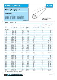
SINGLE PIPES 3:101Straight pipes<strong>Series</strong> 1Article no 12m, <strong>Series</strong> 1: 1103-DN-000-000Article no 16m, <strong>Series</strong> 1: 1104-DN-000-000Article no 18m, <strong>Series</strong> 1: 1105-DN-000-000PN 16/PN25Regarding heatlosssee chapter 9!ARTICLE NO 1103, 1104Transmission capacityService pipe Jacket pipe Weight Water - Δ T = 50°CDN Dy x s [mm] DY [mm] [kg/m] content [l/m] [m/s] [kW]L = 12 m25 33,7 x 2,3 90 3,1 0,6 0,8 10032 42,4 x 2,6 110 4,3 1,1 0,8 18040 48,3 x 2,6 110 4,6 1,5 0,9 23050 60,3 x 2,9 125 6,1 2,3 0,9 37065 76,1 x 2,9 140 7,4 3,9 1,0 70080 88,9 x 3,2 160 9,4 5,3 1,0 1.000100 114,3 x 3,6 200 13,6 9,0 1,1 1.800125 139,7 x 3,6 225 16,6 13,8 1,3 3.300150 168,3 x 4,0 250 21,5 20,2 1,4 5.000200 219,1 x 4,5 315 31,9 34,7 1,6 10.000250 273,0 x 5,0 400 43,9 54,3 1,8 18.000300 323,9 x 5,6 450 60,0 76,8 2,0 28.000350 355,6 x 5,6 500 68,3 93,1 2,0 34.000400 406,4 x 6,3 560 86,9 122,0 2,0 45.000450 457,0 x 6,3 560 91,6 155,0 2,0 65.000500 508,0 x 6,3 630 105,4 193,0 2,0 80.000600 610,0 x 7,1 710 138,0 277,0 2,0 110.000700 711,0 x 8,0 800 190,2 378,0 2,0 160.000800 813,0 x 8,8 900 222,0 497,0 2,0 210.000900 914,0 x 10,0 1000 261,0 627,0 2,0 265,000L = 16 m100 114,3 x 3,6 200 13,6 9,0 1,1 1.800125 139,7 x 3,6 225 16,6 13,8 1,3 3.300150 168,3 x 4,0 250 21,5 20,2 1,4 5.000200 219,1 x 4,5 315 31,9 34,7 1,6 10.000250 273,0 x 5,0 400 43,9 54,3 1,9 18.000300 323,9 x 5,6 450 60,0 76,8 2,0 28.000350 355,6 x 5,6 500 68,3 93,1 2,0 34.000400 406,4 x 6,3 560 86,9 122,0 2,0 45.000450 457,0 x 6,3 560 91,6 155,0 2,0 65.000500 508,0 x 6,3 630 105,4 193,0 2,0 80.000600 610,0 x 7,1 710 138,0 277,0 2,0 110.000700 711,2 x 8,0 800 190,2 378,0 2,0 160.000800 812,8 x 8,8 900 222,0 497,0 2,0 210.000900 914,0 x 10,0 1000 261,0 627,0 2,0 265,000L = 18 m Article D> 100 (excl. DN125)Edition 2013
SINGLE PIPES 3:102Straight pipes<strong>Series</strong> 2Article no 12m, <strong>Series</strong> 2: 1203-DN-000-000Article no 16m, <strong>Series</strong> 2: 1204-DN-000-000Article no 18m, <strong>Series</strong> 2: 1205-DN-000-000PN 16/PN25Regarding heatlosssee chapter 9!ARTICLE NO 1203, 1204Transmission capacityService pipe Jacket pipe Weight Water - Δ T = 50°CDN Dy x s [mm] DY [mm] [kg/m] content [l/m] [m/s] [kW]L = 12 m20 26,9x2,0 110 3,3 0,4 0,8 6525 33,7x2,3 110 3,5 0,6 0,8 10032 42,4x2,6 125 4,6 1,1 0,8 18040 48,3x2,6 125 5,0 1,5 0,9 23050 60,3x2,9 140 6,5 2,3 0,9 37065 76,1x2,9 160 8,0 3,5 1,0 70080 88,9x3,2 180 10,1 5,3 1,0 1.000100 114,3x3,6 225 14,8 9,0 1,1 1.800125 139,7x3,6 250 17,7 13,8 1,3 3.300150 168,3x4,0 280 23,6 20,2 1,4 5.000200 219,1x4,5 355 35,1 34,7 1,6 10.000250 273,0x5,0 450 47,0 54,3 1,8 18.000300 323,9x5,6 500 65,5 76,8 2,0 28.000350 355,6x5,6 560 75,7 93,1 2,0 34.000400 406,4x6,3 630 96,3 121,7 2,0 45.000450 457,0x6,3 630 101,0 155,0 2,0 65 000500 508,0x6,3 710 118,0 193,0 2,0 80.000600 610,0x7,1 800 153,6 277,0 2,0 110.000700 711,0x8,0 900 210,0 378,0 2,0 160.000800 813,0x8,8 1000 246,0 497,0 2,0 210.000900 914,0x10.0 1100 276,0 627,0 2,0 265,000L = 16 m100 114,3x3,6 225 14,8 9,0 1,1 1.800125 139,7x3,6 250 17,7 13,8 1,3 3.300150 168,3x4,0 280 21,5 20,2 1,4 5.000200 219,1x4,5 355 35,1 34,7 1,6 10.000250 273,0x5,0 450 47,0 54,3 1,8 18.000300 323,9x5,6 500 65,5 76,8 2,0 28.000350 355,6x5,6 560 75,7 93,1 2,0 34.000400 406,4x6,3 630 96,3 122,0 2,0 45.000450 457,0x6,3 630 101,0 155,0 2,0 65.000500 508,0x6,3 710 118,0 193,0 2,0 80.000600 610,0x7,1 800 153,6 277,0 2,0 110.000700 711,0x8,0 900 210,0 378,0 2,0 160.000800 813,0x8,8 1000 246,0 497,0 2,0 210.000900 914,0x10,0 1100 276,0 627,0 2,0 265,000L = 18 m Article D> 100 (excl. DN125)Edition 2013
SINGLE PIPES 3:103Straight pipes<strong>Series</strong> 3Article no 12m, <strong>Series</strong> 3: 1303-DN-000-000Article no 16m, <strong>Series</strong> 3: 1304-DN-000-000Article no 18m, <strong>Series</strong> 3: 1305-DN-000-000PN 16/PN25Regarding heatlosssee chapter 9!ARTCLE NO 1303, 1304Transmission capacityService pipe Jacket pipe Weight Water - Δ T = 50°CDN Dy x s [mm] DY [mm] [kg/m] content [l/m] [m/s] [kW]L = 12 m20 26,9x2,0 125 3,7 0,4 0,8 6525 33,7x2,3 125 3,9 0,6 0,8 10032 42,4x2,6 140 5,0 1,1 0,8 18040 48,3x2,6 140 5,4 1,5 0,9 23050 60,3x2,9 160 7,1 2,3 0,9 37065 76,1x2,9 180 8,7 3,5 1,0 70080 88,9x3,2 200 10,9 5,3 1,0 1.000100 114,3x3,6 250 16,2 9,0 1,1 1.800125 139,7x3,6 280 19,9 13,8 1,3 3.300150 168,3x4,0 315 25,7 20,2 1,4 5.000200 219,1x4,5 400 39,0 34,7 1,6 10.000250 273,0x5,0 500 51,4 54,3 1,8 18.000300 323,9x5,6 560 76,9 76,8 2,0 28.000350 355,6x5,6 630 85,1 93,1 2,0 34.000400 406,4x6,3 710 108,8 122,0 2,0 45.000450 457,0x6,3 710 113,5 155,0 2,0 65.000500 508,0x6,3 800 133,6 193,0 2,0 80.000600 610,0x7,1 900 173,0 277,0 2,0 110.000700 711,0x8,0 1000 231,8 378,0 2,0 160.000800 812,8x8,8 1100 267,0 497,0 2,0 210,000L = 16 m100 114,3x3,6 250 16,2 9,0 1,1 1.800125 139,7x3,6 280 19,9 13,8 1,3 3.300150 168,3x4,0 315 25,7 20,2 1,4 5.000200 219,1x4,5 400 39,0 34,7 1,6 10.000250 273,0x5,0 500 51,4 54,3 1,8 18.000300 323,9x5,6 560 76,9 76,8 2,0 28.000350 355,6x5,6 630 85,1 93,1 2,0 34.000400 406,4x6,3 710 108,8 122,0 2,0 45.000450 457,0x6,3 710 113,5 155,0 2,0 65.000500 508,0x6,3 800 133,6 193,0 2,0 80.000600 610,0x7,1 900 173,0 277,0 2,0 110.000700 711,0x8,0 1000 231,8 378,0 2,0 160.000800 812,8x8,8 1100 267,0 497,0 2,0 210,000L = 18 m Article D> 100 (excl. DN125)Edition 2013
SINGLE PIPES 3:104Straight pipes<strong>Series</strong> 4Article no 12m, <strong>Series</strong> 4: 1403-DN-000-000Article no 16m, <strong>Series</strong> 4: 1404-DN-000-000Article no 18m, <strong>Series</strong> 4: 1405-DN-000-000PN 16/PN25Regarding heatlosssee chapter 9!ARTICLE N0 1403, 1404Transmission capacityService pipe Jacket pipe Weight Water - Δ T = 50°CDN Dy x s [mm] DY [mm] [kg/m] content [l/m] [m/s] [kW]L = 12 m20 26,9x2,3 140 4,1 0,4 0,8 6525 33,7x2,6 140 4,4 0,6 0,8 10032 42,4x2,6 160 5,5 1,1 0,8 18040 48,3x2,6 160 6,0 1,5 0,9 23050 60,3x2,9 180 7,8 2,3 0,9 37065 76,1x2,9 200 9,6 3,5 1,0 70080 88,9x3,2 225 11,9 5,3 1,0 1.000100 114,3x3,6 280 17,4 9,0 1,1 1.800125 139,7x3,6 315 22,5 13,8 1,3 3.300150 168,3x4,0 355 28,0 20,2 1,4 5.000200 219,1x4,5 450 42,0 34,7 1,6 10.000250 273,0x5,0 560 56,6 54,3 1,8 18.000300 323,9x5,6 630 82,5 76,8 2,0 28.000350 355,6x5,6 710 93,5 93,1 2,0 34.000400 406,4x6,3 800 119,0 122,0 2,0 45.000450 457,0x6,3 800 124,0 155,0 2,0 65.000500 508,0x6,3 900 147,0 193,0 2,0 80.000600 610,0x7,1 1000 189,0 277,0 2,0 110.000700 711,0x8,0 1100 248,0 378,0 2,0 160.000L = 16 m100 114,3x3,6 280 17,4 9,0 1,1 1.800125 139,7x3,6 315 22,5 13,8 1,3 3.300150 168,3x4,0 355 28,0 20,2 1,4 5.000200 219,1x4,5 450 42,0 34,7 1,6 10.000250 273,0x5,0 560 56,6 54,3 1,8 18.000300 323,9x5,6 630 82,5 76,8 2,0 28.000350 355,6x5,6 710 93,5 93,1 2,0 34.000400 406,4x6,3 800 119,0 122,0 2,0 45.000450 457,0x6,3 800 124,0 155,0 2,0 65.000500 508,0x6,3 900 147,0 193,0 2,0 80.000600 610,0x7,1 1000 189,0 277,0 2,0 110.000700 711,0x8,0 1100 248,0 378,0 2,0 160.000L = 18 m Article D> 100 (excl. DN125)Edition 2013
SINGLE PIPES 3:105Straight pipes for cutto-length<strong>Series</strong> 1, 2, 3 <strong>and</strong> 4Cutting Kapzoner zone everyvarannan metersecond metrePN 16/PN25Cut-to-length pipes are manufactured in all dimensions. In these pipes the steel service pipe is covered by a plasticfoil every second metre along the entire pipe length. This arrangement allows easy removal of the foam from the steel in thesections. These sections of the pipe are indicated on the outside casing pipe. Whole lengths or parts of pipes cut-to-lengthcan be installed at any place in a district heating distribution system.CUT-TO-LENGTH PIPE 1113, 1213, 1313, 1413L = 12 mArticle no. <strong>Series</strong> 11113-DNArticle no. <strong>Series</strong> 2For measurement details, see straight pipes!1213-DNArticle no. <strong>Series</strong> 31313-DNArticle no. <strong>Series</strong> 41413-DNCUT-TO-LENGTH PIPE 1114, 1214, 1314, 1414L = 16 mArticle no. <strong>Series</strong> 11114-DNArticle no. <strong>Series</strong> 2For measurement details, see straight pipes!1214-DNArticle no. <strong>Series</strong> 31314-DNArticle no. <strong>Series</strong> 41414-DNCUT-TO-LENGTH PIPE 1115, 1215, 1315, 1415L = 18 mArticle no. <strong>Series</strong> 11115-DNArticle no. <strong>Series</strong> 2For measurement details, see straight pipes!1215-DNArticle no. <strong>Series</strong> 31315-DNArticle no. <strong>Series</strong> 41415-DNPipes are available with «center-cut" This will be indicated in separate line of text.An example of how to order:Cut-to-length pipe DN 200, series 2, 12 m has Article no. 1213-200-000-000.Edition 2013
SINGLE PIPES 3:106Curved pipes<strong>Series</strong> 1, 2, 3 <strong>and</strong> 4deflectionPN 16/PN25CURVED PIPES 1123, 1124, 1223, 1224, 1323, 1324, 1423, 1424Single pipesMax. deflectionDN L = 12 m L = 16 m Note25 - 80 35 o To be bent at installation site80 - 100 35 o Bent at <strong>Powerpipe</strong> works125 - 150 30 o 25 o Bent at <strong>Powerpipe</strong> works200 25 o 33 o Bent at <strong>Powerpipe</strong> works250 25 o 33 o Bent at <strong>Powerpipe</strong> works300 20 o 25 o Bent at <strong>Powerpipe</strong> works350 14 o 23 o Bent at <strong>Powerpipe</strong> works400 11-(18) o 15-(22) o Bent at <strong>Powerpipe</strong> works *450 7-(11) o 11-(18) o Bent at <strong>Powerpipe</strong> works *500 5-(9) o 8-(12) o Bent at <strong>Powerpipe</strong> works *600 – 8 o Bent at <strong>Powerpipe</strong> works*700 – 4 o Bent at <strong>Powerpipe</strong> works** See note below concerning wall thickness. wall thickness below. In paranteses; the specified values relatesthickness higher than st<strong>and</strong>ard.Accuracy of manufacture DN 100 - 200 +/- 2°DN 250 - 600 +/- 1°Steel pipes:For the manufacturing either seamless steel pipes or longitudinally welded steel pipes are used.DN 450, DN 500, DN 600 <strong>and</strong> DN700 steel pipes with extra wall thickness will be used. Increasedwall thickness for smaller dimensions will allow deflection exceeding above normal max. deflection.This can be delivered on request. However, this means increased prices <strong>and</strong> longer deliverytime. For larger sizes (DN700-900) segment-welded curved pipes can be offered.For manufacturing technical reasons, the alarm wires placed in neutral position, ie c. at. 12 <strong>and</strong> 6.Article no. series 11123-DN-xxx-000 for 12 m pipe length1124-DN-xxx-000 for 16 m pipe lengthArticle no. series 21223-DN-xxx-000 for 12 m pipe length1224-DN-xxx-000 for 16 m pipe lengthArticle no. series 31323-DN-xxx-000 for 12 m pipe length1324-DN-xxx-000 for 16 m pipe lengthArticle no. series 41423-DN-xxx-000 for 12 m pipe length1424-DN-xxx-000 for 16 m pipe lengthxxx = degreesAn example of how to order:Curved pipe series 1, L = 12 m with dim DN 200 <strong>and</strong> curved 15 ohas Article No. 1123-200-015-000, Deflection shall be stated in a separate line of text.Edition 2013
SINGLE PIPES 3:107Curved pipes - HorizontalDeflection versus designradius<strong>Series</strong> 1, 2, 3 <strong>and</strong> 4PN 16/PN25Design radiusLengthDeflectionCORRELATION BETWEEN DEFLECTION AND DESIGN RADIUSDesign radiusDesign radiusDeflection L = 12 m L = 16 m Deflection L = 12 m L = 16 m1° 690 910 21° 33,0 44,02° 345 460 22° 31,0 42,03° 230 305 23° 30,0 40,04° 170 230 24° 29,0 38,05° 140 185 25° 28,0 37,06° 115 155 26° 27,0 36,07° 98 130 27° 26,0 34,08° 86 115 28° 25,0 33,09° 76 100 29° 24,0 32,010° 69 92 30° 23,2 30,911° 62 83 31° 22,5 30,012° 57 76 32° 21,8 29,113° 53 71 33° 21,1 28,114° 49 65 34° 20,5 27,315° 46 61 35° 20,0 26,716° 43 57 36° 19,4 25,817° 40 54 37° 18,9 25,218° 38 51 38° 18,4 24,619° 36 48 39° 18,0 23,920° 34 46 40° 17,5 23,4Pipe trench:A pre-insulated pipe DN>250 cannot be bent along its entire length. At each pipe end astraight part will remain, which shall be approximately 2 meters in length.This deviation from an ideal curved pipe radius is to be compensated when installing the pipeby making the pipe trench approximately 150 mm wider.The widening should be ~200 mm at deviation < 10 oThe widening should be ~500 mm at deviation > 10 oEdition 2013
SINGLE PIPES 3:108Curved pipesElastic radiusdeflection<strong>Series</strong> 1, 2 , 3 <strong>and</strong> 4Design radiusLengthPN 16/PN25ELASTIC RADIUSDimension Elastic radius DeflectionDN m 12 m25 15 45,0°40 21 31,0°50 27 25,0°65 34 20,0°80 40 17,0°100 52 13,0°125 63 11,0°150 76 9,0°200 98 7,0°250 122 5,6°300 145 4,7°400 182 3,7°500 227 3,0°600 273 2,5°The above table shows the elastic radius which is the maximum radius or deflection that canbe allowed without permanent deformation of the steel pipe.Edition 2013
SINGLE PIPES 3:201Bend horizontal<strong>Series</strong> 1, 2, 3 <strong>and</strong> 4<strong>Powerpipe</strong> bends are manufactured using a specialfoam with high compressive strength., which meansthat motionabsorbent material would normallybe unnecessaryARTICLE NO 2100, 2200, 2300, 2400PN 16/PN25Service pipeJacket pipe<strong>Series</strong> 1 <strong>Series</strong> 2 <strong>Series</strong> 3 <strong>Series</strong> 4 LDN Dy x s [mm] DY [mm] DY [mm] DY [mm] DY [mm] [mm]20 26,9x2,3 - 110 125 140 100025 33,7x2,6 90 110 125 140 100032 42,4x2,6 110 125 140 160 100040 48,3x2,6 110 125 140 160 100050 60,3x2,9 125 140 160 180 100065 76,1x2,9 140 160 180 200 100080 88,9x3,2 160 180 200 225 1000100 114,3x3,6 200 225 250 280 1000125 139,7x3,6 225 250 280 315 1000150 168,3x4,0 250 280 315 355 1000200 219,1x4,5 315 355 400 450 1000250 273,0x5,0 400 450 500 560 1300300 323,9x5,6 450 500 560 630 1500350 355,6x5,6 500 560 630 710 1600400 406,4x6,3 560 630 710 800 1600450 457,0x6,3 560 530 710 800 1600500 508,0x6,3 630 710 800 900 1600600 610,0x7,1 710 800 900 1000 1600700 711,0x8,0 800 900 1000 1100 1700800 813,0x8,8 900 1000 1100 1850900 914,0x10,0 1000 1100 2000Bends are, as st<strong>and</strong>ard, available as 90° <strong>and</strong> 45°.Bends having other degrees, such as 75°, 60°, 30° <strong>and</strong> 15°, <strong>and</strong> bends having leg lengths other thanspecified in the above table can be delivered on special request.Article no. <strong>Series</strong> 12100-DN-degree of bend-000Article no. <strong>Series</strong> 22200-DN-degree of bend-000Space for sleeveIn order to fit the sleeve at installation of DN50-DN200 extendedleg 1200x 1200 mm are offered. State suffix 999thArticle no. <strong>Series</strong> 3An example of how to order:2300-DN-degree of bend-000 Bend, series 1, dim DN100, 90°has Article No. 2100-100-900-000.Article no. <strong>Series</strong> 42400-DN-degree of bend-000Edition 2013
SINGLE PIPES 3:202Termination bend 90°Vertical<strong>Series</strong> 1, 2, 3 <strong>and</strong> 41500Termination bends are delivered in 90 o as st<strong>and</strong>ard.Can be ordered with end cap1500PN 16/PN25ARTICLE NO 2110, 2210, 2310Service pipeJacket pipe<strong>Series</strong> 1 <strong>Series</strong> 2 <strong>Series</strong> 3 <strong>Series</strong> 4DN Dy x s [mm] DY [mm] DY [mm] DY [mm] DY [mm]20 26,9x2,3 – 110 125 14025 33,7x2,6 90 110 125 14032 42,4x2,6 110 125 140 16040 48,3x2,6 110 125 140 16050 60,3x2,9 125 140 160 18065 76,1x2,9 140 160 180 20080 88,9x3,2 160 180 200 225100 114,3x3,6 200 225 250 280125 139,0x3,6 225 250 280 315150 168,3x4,0 250 280 315 355200 219,1x4,5 315 355 400 450250 273,0x5,0 400 450 500 560300 323,9x5,6 450 500 560 630Other degrees <strong>and</strong>/or leg lengths can be supplied on request.Article no. series 12110-DN-000-000Article no. series 22210-DN-000-000Article no. series 32310-DN-000-000Article no. series 42410-DN-000-000Can be ordered with end cap (State suffix-811)Termination bend, 90 o , with other leg lengths <strong>and</strong> deflectioncan be delivered on request.An example of how to order:Termination bend series 1dim DN 50, has article no. 2110-050-000-000.Gravel refilling may not reach thealarm wire.The sealing shall not be belowwater tabe continuously.Keep the plastic emballage onduring the installation!Edition 2013
SINGLE PIPES 3:301T-piece<strong>Series</strong> 1, 2, 3 <strong>and</strong> 4<strong>Powerpipe</strong> T-pieces are as st<strong>and</strong>ard delivered in areinforced design if not otherwise is indicated.PN 16/PN25ARTICLE NO 3100, 3200, 3300, 3400Main pipe Branch pipe L1 L2DN DN [mm] [mm]25-200 25-80 1200 1000100-200 100-200 1500 1000250-900 25-80 1200 1200250-900 100-200 1500 1200250-900 250-600 1800 1500700-900 700-900 2100 1700The branch pipe cannot be designed in dimensions bigger than the main pipe.Article no. series 13100-DN main pipe-DN branch pipe-000Article no. series 23200-DN main pipe-DN branch pipe-000Article no. series 33300-DN main pipe-DN branch pipe-000Space for sleeveIn order to fit the sleeve at installation of T-piece withbranch pipe max DN200, product with extended L1-dimensions with 800 mm are offered <strong>and</strong> L2-dimensionswith 400 mm for DN 25-80, L2-dimensions with700 mm for DN 100-200State suffix: 999.Article no. series 43400-DN main pipe-DN branch pipe-000An example of how to order:T-piece series 1 med main pipe DN 200 <strong>and</strong> branch pipe DN 50,has article no. 3100-200-050-000.Alt. (extended T-piece) has article no. 3100-200-050-999Edition 2013
L3L2SINGLE PIPES 3:302T-piece withextended branch<strong>Series</strong> 1, 2, 3 <strong>and</strong> 4<strong>Powerpipe</strong> T-pieces with extended branch length shallbe used in such cases when the systems design requirethe installation of a valve unit or a transition unitin the branch directly after the T-piece. PN 16/PN25ARTICLE NO 3120, 3220, 3320, 342050L1Main pipe For L1 <strong>and</strong> L2 L3 [mm] L3 [mm]DN see page 3:301 <strong>Series</strong> 1 <strong>and</strong> 2 <strong>Series</strong> 3 <strong>and</strong> 425-50 33065-80 370100-125 500150 530200 600250 700300 750 860350 850 930400 930 1000500 1000 1100600 1100 1200700 1200 1300800 1300 1400900 1400 1500The branch pipe cannot be designed in dimensions bigger than the main pipeArticle no. series 13120-DN main pipe-DN branch pipe-000Article no. series 23220-DN main pipe-DN branch pipe-000Article no. series 33320-DN main pipe-DN branch pipe-000Article no. series 43420-DN main pipe-DN branch pipe-000An example of how to order:T-piece series 1 with main pipe DN 200 <strong>and</strong> branch pipe DN 50,has Article No. 3120-200-050-000.Edition 2013
SINGLE PIPES 3:303T-piece, straight<strong>Series</strong> 1, 2, 3 <strong>and</strong> 4<strong>Powerpipe</strong> T-pieces are as st<strong>and</strong>ard delivered in areinforced design if not otherwise is indicated.With T-piece straight branching can be performedat the same level as the main pipe.PN 16/PN25L1L2ARTICLE NO 3130, 3230, 3330, 3430Main pipe Branch pipe L1 L2DN DN [mm] [mm]25-200 25-100 1200 700125-200 125-200 1500 700250-500 25-100 1200 900250-500 125-200 1500 900250-500 250-400 1800 900600-900 25-100 1200 1100600-900 125-200 1500 1100600-900 250-500 1800 1100600-900 600-800 2100 1100The branch pipe cannot be designed in dimensions bigger than the main pipe.Article no. series 13130-DN main pipe-DN branch pipe-000Article no. series 23230-DN main pipe-DN branch pipe-000Article no. series 33330-DN main pipe-DN branch pipe-000Article no. series 43430-DN main pipe-DN branch pipe-000An example of how to order:T-piece series 1 with main pipe DN 200 <strong>and</strong> branch pipe DN 50,has Article No. 3130-200-050-000.Edition 2013
SINGLE PIPES 3:304T-pieces withparallel branch<strong>Series</strong> 1, 2, 3 <strong>and</strong> 4<strong>Powerpipe</strong> T-pieces are as st<strong>and</strong>ard delivered ina reinforced design if not otherwise is indicated.H150L1PN 16/PN25ARTICLE NO 3110, 3210, 3310, 3410Main pipe Branch pipe L1DN DN [mm]25-900 25-100 1200125-900 125-200 1500250-900 250-400 1800450-900 450-500 2400H = DY Main pipe + DY Branch pipe + 150 (For branch pipe DN450 <strong>and</strong> DN500 the H-dimension will be100mm more)2Example:Main pipe DN 100/225Branch pipe DN 40/125H = 225 + 125 +150 = 325 mm2The branch pipe cannot be designed in dimensions larger than the main pipe.See chapter 7:301 for how alarm systems are madeArticle no. series 13110-DN main pipe-DN branch pipe-000Article no. series 23210-DN main pipe-DN branch pipe-000Article no. series 33310-DN main pipe-DN branch pipe-000Article no. series 43410-DN main pipe-DN branch pipe-000An example of how to order:T-piece series 1 with main pipe DN 200 <strong>and</strong> branch pipe DN 50,has Article No. 3110-200-050-000.Edition 2013
SINGLE PIPES B 3:305Air release/ drainageunits<strong>Series</strong> 1, 2, 3 <strong>and</strong> 4The built in alarmwires are linked outside the sealing.H1500 1200PN 16/PN25ARTICLE NO 3140, 3240, 3340, 3440Main pipe H Air release/ drainage B-measureDN [mm] DN [mm]25 409 25 11032 414 40 11040 417 50 12550 423 65 14065 43180 438100 450125 463150 477200 502250 530300 554350 570400 596500 650600 700700 758800 800900 850Please observe: the includedball valve has to be operatedat least twice/year in order toensure a good function.The valve is made of stainless steel. Air release/ drainage unitsare equipped with screwed on plug <strong>and</strong> comes in DN 25, DN 40,DN 50 <strong>and</strong> DN65. As air release unit DN25 is recomended <strong>and</strong> asdrain unit DN50 is recomended.The valve is protected by a end cap as a st<strong>and</strong>ard. Se sid 8:102Please observe: Do not refillabove the sealing.The sealing shall not be belowwater tabe continuously.Article no. series 1 Article no. series 33140-DN main pipe-DN release/ drainage-0003340-DN main pipe-DN release/ drainage-000Article no. series 2 Article no. series 43240-DN main pipe-DN release/ drainage-0003440-DN main pipe-DN release/ drainage-000An example of how to order:Air release for main pipe series 1 with main pipe DN 200 <strong>and</strong>air release DN 25, has Article No. 3140-200-025-000.Edition 2013
SINGLE PIPES 3:401Valves<strong>Series</strong> 1, 2, 3 <strong>and</strong> 4The unit consists of a maintenance free ball valve in afully welded housing together with a corrosion free ball.All valves according to EN448 are supplied to st<strong>and</strong> theyield strength as the pipe line. The built in alarmwires arelinked outside the sealing. When using fixed gear, orderthe placement for alarm wire separately.PN 16/PN25LARTICLE NO 4100, 4200, 4300, 4400Main pipe Service pipe L H B Wrench size LevererasDN Dy x s mm [mm] [mm] [mm] [mm] med25 33,7 x 2,3 1500 382 110 1932 42,4 x 2,6 1500 388 110 1940 48,3 x 2,6 1500 401 110 1950 60,3 x 2,9 1500 411 110 19 Mount for65 76,1 x 2,9 1500 415 110 19 T-key80 88,9 x 3,2 1500 426 110 19100 114,3 x 3,6 1500 450 125 27125 139,7 x 3,6 1500 455 125 27150 168,3 x 4,0 1500 474 125 27200 219,1 x 4,5 1500 520 160 50 mount for250 273,0 x 5,0 1500 557 160 50 portable gear300 323,9 x 5,6 1800 664 160 50350 355,6 x 5,6 1800 906 350400 406,4 x 6,3 2000 977 350 Fixed gear500 508,3x6,3 custom 1056 350600 610,0x7,1 custom 1183 350H-measure does not include gear, hydraulic or electric actuator. For valves DN700 <strong>and</strong> DN800 see separatespecification. Gate valve can be quoted on request. Other design for example with full bore can be supplied onrequest. Valves can be supplied with T-key, portable planetary gear <strong>and</strong> protection pipe for valve stem extension,length 1500 mm, <strong>and</strong> hydraulic or electric actuator, see accessories!AS st<strong>and</strong>ard the valves are delivered with:DN25-DN125 with mount for T-key.DN150-DN300 with mount for portable gear.DN350-DNxx with fixed gear.Article no. series 1 Article no. series 24100-DN-000-0004200-DN-000-000Article no. series 3 Article no. series 44300-DN-000-0004400-DN-000-000The valve is protected by a end cap of PEH as a st<strong>and</strong>ard. See 8:102Available with separate measuring box as extra order, se 7:302.An example of how to order:Valves series 1 with main pipe DN 200,has Article No. 4100-200-000-000.Please observe: the included ballvalve has to be operated at leasttwice/year in order to ensure agood function.Please observe: Do not refill abovethe sealing.The sealing shall not be belowwater tabe continuously.Edition 2013
B DSINGLE PIPES 3:402Preinsulated valvewith one air release/drainage unit<strong>Series</strong> 1, 2, 3 <strong>and</strong> 4The built in alarmwires are linked outside the sealing.When using fixed gear, order the placementfor alarm wire separately.PN 16/PN25CLARTICLE NO 4141, 4241, 4341, 4441Air release/ drainageMain pipe L C H B Wrench size Delivered D-dimDN [mm] [mm] [mm] [mm] [mm] with DN [mm]25 1500 250 382 110 19 25 11032 1500 250 388 110 19 40 11040 1500 250 401 110 19 50 12550 1500 250 411 110 19 Mount 65 14065 1500 250 415 110 19 for T-key80 1500 250 426 110 19100 1500 250 450 125 27125 1500 250 455 125 27150 1500 250 474 125 27200 1500 250 520 160 50 Mount for250 1500 350 557 160 50 portable gear300 1800 350 664 160 50350 1800 350 906 350400 2000 450 977 350 Fixed gear500 2200 550 1056 350600 2400 640 1183 350The valve stems are installed in position towards the stop valve. Air release/ drainage units are manufactured indimension DN25, DN40, DN50 <strong>and</strong> DN65 are delivered with a screwed on plug. Both air release/ drainageunits are delivered in the same dimension.The valve is protected by a end cap as a st<strong>and</strong>ard. Se sid 8:102Article no. series 1 Article no. series 24141-DN main pipe-DN air release-000 4241-DN main pipe-DN air release-000Article no. series 34341-DN main pipe-DN air release-000Article no. series 44441-DN main pipe-DN air release-000Available with separate measuring box as extra order, see 7:302An example of how to order:Valve series 2 with main pipe DN 100 <strong>and</strong> air release DN 25,has Article No. 4241-100-025-000.Please observe: the includedball valve has to be operatedat least twice/year in order toensure a good function.Please observe: Do not refillabove the sealing.The sealing shall not be belowwater tabe ontinously.Edition 2013
SINGLE PIPES 3:403Valve with double airrelease/drainage units<strong>Series</strong> 1, 2, 3 <strong>and</strong> 4The built in alarmwires are linked outside the sealing.When using fixed gear, order the placementfor alarm wire separately.PN 16/PN25DCCLSt<strong>and</strong>ard design(See alternative design at page 3;404)HARTICLE NO 4142, 4242, 4342, 4442Air release/ drainageMain pipe L C H Wrench size DN D-dimSt<strong>and</strong>ard[mm]DN [mm] [mm] [mm] [mm]25 1500 250 382 19 25 11032 1500 250 388 19 40 11040 1500 250 401 19 50 125Mount50 1500 250 411 19 65 140for65 1500 250 415 19T-key80 1500 250 426 19100 1500 250 450 27125 1500 250 455 27150 1500 250 474 27 Mount200 1500 250 520 50 for250 1500 350 557 50 portable300 1800 350 664 50 gear350 1800 350 906400 2000 450 977Fixed500 2200 550 1056gear600 2400 640 1183The valve stems are installed in position towards the stop valve. Air release/ drainage units are manufactured indimension DN25, DN40, DN50 <strong>and</strong> DN65 are delivered with a screwed on plug. Both air release/ drainageunits are delivered in the same dimension.The valve is protected by a end cap as a st<strong>and</strong>ard. Se sid 8:102Article no. series 14142-DN main pipe-DN air release-000Article no. series 24242-DN main pipe-DN air release-000Article no. series 34342-DN main pipe-DN air release-000Article no. series 44442-DN main pipe-DN air release-000An example of how to order:Valve series 2 with main pipe DN 100 <strong>and</strong> air releaseDN 25, has Article No. 4242-100-025-000.Please observe: the included ball valve has to beoperated at least twice/year in order to ensure agood function.Please observe: Do not refill above the sealing.The sealing shall not be below water tabecontinously.Edition 2013
DesignDpSINGLE PIPES 6223:404Valve with 2 pc. airreleasear/drainage(optional design)DHLDCDH<strong>Series</strong> 1, 2, 3 <strong>and</strong> 4The built in alarmwires are linked outside the sealing.When using fixed gear, order the placementfor alarm wire separately.PN 16/PN25Design637L1.500ARTICLE NO 4142, 4242, 4342, 4442Air release/ drainageMain pipe L L C H Dp Wrench size DN D-dim622 637 [mm] [mm]DN [mm] [mm] [mm] [mm] [mm] [mm]25 1500 2750 250 382 235 19 25 11032 1500 2750 250 388 235 19 40 11040 1500 2750 250 401 235 19 50 125Mount50 1500 2750 250 411 235 19 65 140for65 1500 2750 250 415 295 19T-Key80 1500 2750 250 426 295 19100 1500 2750 250 450 295 27125 1500 2750 250 455 340 27150 1500 2750 250 474 415 27 Mount200 1500 2750 250 520 415 50 for250 1500 2850 350 557 415 50 portabel300 1800 2850 350 664 415 50 gear350 1800 2850 350 906400 2000 2950 450 977Fixed500 2200 3050 550 1056gear600 2400 3150 640 1183The valve stems are installed in position towards the stop valve. Air release/ drainage units are manufactured indimension DN25, DN40, DN50 <strong>and</strong> DN65 are delivered with a screwed on plug. Both air release/ drainageunits are delivered in the same dimension.The valve is protected by a end cap as a st<strong>and</strong>ard. Se sid 8:102Design 622 has suffix 622Design 637 has suffix 637An example of how to order:Valve series 2 with main pipe DN 300 <strong>and</strong> airrelease DN 40 in design 622, has Article No.4242-300-040-622 <strong>and</strong> design 637 hasArticle No. 4242-300-040-637Please observe: the included ball valve has to beoperated at least twice/year in order to ensure agood function.Please observe: Do not refill above the sealing.The sealing shall not be below water tabecontinously.Edition 2013
DesignSINGLE PIPES 3:405Valve with 2 pc. protectedair release/drainage (optional design)635DpDAHL2<strong>Series</strong> 1, 2, 3 <strong>and</strong> 4The built in alarmwires are linked outsidethe sealing.PN 16/PN25LARTICLE NO 4142, 4242, 4342, 4442 Design 635Air release/ drainageMain pipe L Dp Air release H Wrench size DN DA L2DN [mm] [mm]DN [mm] [mm] [mm] [mm] [mm]25 1500 382 19 25 150 30032 1500 388 19 40 180 35040 1500 180 25 401 1950 1500 180 25 411 1965 1500 180 25 415 1980 1500 180 25 426 19100 1500 180 25 450 27125 1500 180 25 455 27150 1500 180 25 474 27200 1500 225 40 520 50250 1500 225 40 557 50300 1800 225 40 664 50MountforT-KeyMountforportablegearAir release/ drainage units are manufactured in dimension DN25, DN40, DN50 <strong>and</strong> DN65 are deliveredwith a screwed on plug.desired connections can be executed in the threaded end. Valve spindles are facing upwards.Both air release / drainage units are delivered in the same dimension.The valve is protected by a hut as a st<strong>and</strong>ard. Please see 8:102An example of how to order:Valve series 2 with main pipe DN 300 <strong>and</strong>air release DN 40 in design 635, has Article No.4242-300-040-635Please observe: the included ball valve has to beoperated at least twice/year in order to ensure agood function.Please observe: Do not refill above the sealing.The sealing shall not be below water tabecontinously.Edition 2013
SINGLE PIPES 3:406Combination valveSt<strong>and</strong>ard design<strong>Series</strong> 1, 2, 3 <strong>and</strong> 4● Air release● Drain● BypassARTICLE NO 4841, 4842, 4843, 4844PN 16/PN25Main pipe D By pas valves L A D A B H<strong>Series</strong> 2 ValvesDN [mm] DN (3 st) [mm] [mm] [mm] [mm] [mm]100 225 25 1800 650 110 415 500125 250 25 1800 650 125 415 500150 280 32 1800 700 125 415 530200 355 40 1800 700 125 415 560250 450 40 1800 700 125 450 600300 500 50 2100 750 140 450 700DHBLD ASt<strong>and</strong>ard design<strong>AB</strong>all valve comes with mount for T-key (DN 25-125) or portable gear (DN 150-300).Drainage pipe <strong>and</strong> valve are made of stainless steel.The valve is protected by a hut as a st<strong>and</strong>ard. Please see 8:102Design of model B, see page 3:406, can be adapted to customerspecific requirements.A measuring box is located between the by pas valves, please see 7:302Article no. 14841-DN-000-000.Seen from aboveAlarm wire penetrationConnectingof valveArticle no. 24842-DN-000-000.Article no. 34843-DN-000-000.Article no. 44844-DN-000-000.An example of how to order:Combination valve for DN 200 hasarticle no. 4843-200-000-000.Principle sketchPlease observe: the includedball valve has to be operatedat least twice/year in order toensure a good function.Please observe: Do not refillabove the sealing.The sealing shall not be belowwater tabe ontinously.Edition 2013
Model BSINGLE PIPES 3:407Combination valveoption designGear VäxelBA<strong>Series</strong> 1, 2, 3 <strong>and</strong> 4D● Air release● Drain● BypassPN 16/PN251.200LARTICLE NO 4843 i design 637Main pipe D Bypass L A D A B H<strong>Series</strong> 2 valvesDN [mm] DN (3 st) [mm] [mm] [mm] [mm] [mm]200 355 40 3000 650 125 650 560250 450 40 3000 700 125 650 600300 500 50 3000 750 140 700 700350 560 50 3200 800 140 940400 680 50 3400 800 140 940500 710 50 3600 900 140 1135Drainage pipe <strong>and</strong> valve are made of stainless steel.The optional design can be adapted to specific customer requirements.The valve can be fitted with fixed gear, hydraulic actuator or electric compnent. The design can be adaptedfor air release or bleed. The length of the outlet pipes can be customisedArticle no.4843-DN-000-637.An example of how to order:Combination valve forDN 200 has article no.4843-200-000-000.Seen from aboveAlarm wire penetrationConnectingof valveMount for gear or componentPrinciple sketchEdition 2013
SINGLE PIPES B 3:408Valve unit compact<strong>Series</strong> 1, 2, 3 <strong>and</strong> 4HC/CThe valve unit is being used for the bleed orair release.It is built to fit in a st<strong>and</strong>ard well.PN 16/PN25L 2Outlet leftL 1ARTICLE NO 4170, 4270, 4370, 4470DN C-C H H B L1 L2St<strong>and</strong>ard Min[mm] [mm] [mm] [mm] [mm]25 310 480 190 316 550 57040 330 495 200 364 560 60050 360 500 210 398 600 62565 420 505 210 412 610 62580 450 515 225 447 620 700The stem height «H» is available with st<strong>and</strong>ard height or min. height i.a. to the table above.The valve unit can be supplemented with loose stem extensions of 250, 500, 750 or 1000 mm.The outlet pipe is made of stainless steel. The valves are supplied with mount for T-key.The valve is protected by a end cap as a st<strong>and</strong>ard. Please see 8:102This product replaces previous «Valve unit, straight» <strong>and</strong> «Unit Valve, bend»Article no. series 1 Article no. series 24170-DN-000-0004270-DN-000-000Article no. series 3 Article no. series 44370-DN-000-0004470-DN-000-000Outlet 45° right has prefix 032Outlet 45° left has prefix 031.Valve unit with minimal spindle height has mid-prefix = H-min.Outlet leftAn example of how to order:Valve unit, compact, right series 2 dim DN50 has article no. 4270-050-000-031.When ordering a minimum stem height, state as indicated below:Valve unit, compact, right, <strong>Series</strong> 2. DN50 with minimalspindle height has article no. 4270-050-210-031Please observe: the included ball valve has to beoperated at least twice/year in order to ensure agood function.Please observe: Do not refill abovethe sealing.The sealing shall not be belowwater tabe ontinously.Edition 2013
SINGLE PIPES 3:501Anchor unitst<strong>Series</strong> 1, 2, 3 <strong>and</strong> 4The anchor unit is designed for casting into concreteof quality K 250. Dimensioning pressure force:In concrete 5 MN/ m 2 (50 kg/cm 2 ), st<strong>and</strong>ard valueIn ground 0,15 MN/ m 2 (1,5 kg/cm 2 ), st<strong>and</strong>ard valuePN 16/PN25A 9002000ARTICLE NO 5100, 5200, 5300, 5400DN Max load (kN) A t Pressure area (<strong>Series</strong> 2)∅ T = 60°C [mm] [mm] [cm 2 ]25 38 200 25 19132 49 220 25 24340 56 220 25 24350 78 240 25 28965 100 280 25 45280 129 300 30 392100 187 350 30 565125 230 400 30 765150 310 450 30 875200 455 550 35 1385250 630 650 40 1730300 840 700 40 1885400 1200 850 40 2560500 1500 1000 65 4000600 2000 1200 65 6200A <strong>and</strong> t measurement are given above for <strong>Series</strong> 2.Article no. series 15100-DN-000-000Article no. series 25200-DN-000-000Article no. series 35300-DN-000-000Article no. series 45400-DN-000-000An example of how to order:Ancor unit series 1 with dim DN 200,has article no. 5100-200-000-000.Edition 2013
SINGLE PIPES 3:502Single-usecompensatorThe single-use compensator can be used forpre-stressing of the pipe line in places wherepre-heating for practical reasons cannot be made.DNDuPN 16/PN25ARTICLE NO 7810DN Max pre-stressing Ln Du[mm]40 50 450 6050 50 450 7065 70 500 9080 70 500 102100 80 550 127125 80 550 152150 100 630 178200 120 700 232250 120 700 286300 140 730 338350 140 730 371400 140 730 426450 150 800 477500 150 800 528600 150 800 635700 150 780 735800 150 850 838Article no.7810-DN-000-000An example of how to order:Single-use compensator for a DN200 pipe line, Article No. 7810-200-000-000,Relatet casing is described in section 6:205Edition 2013
SINGLE PIPES 3:503Reduction unitThe reduction unit is used at change of dimension.An optioin is steel cone + PEH reduction.DN1DN2LPN 16/PN25ARTICLE NO 1571, 1572, 1573, 1574DN1/ DN DN DN DN DN DN DN DN DN DN DN DN DN DN DN DN DNDN2 32 40 50 65 80 100 125 150 200 250 300 350 400 500 600 700 80025 x x32 x x40 x x50 x x65 x x80 x x100 x x125 x x150 x x200 x x250 x x300 x x350 x x400 x x500 x x600 x x700 xThe reduction unit is used at change of dimension. The table lists the default reduction unit.Article no. series 11571-DN1-DN2-000DN1LArticle no. series 2[mm]1572-DN1-DN2-000 DN 25–300 900DN 350–500 1100Article no. series 3 DN 600-800 13001573-DN1-DN2-000Article no. series 41574-DN1-DN2-000An example of how to order:Reduction unit series 1 with dim DN 200 to DN 150has article no. 1571-200-150-000.NOTE:Consult with the designer where thereduction shall be placed <strong>and</strong> whatdimension to choose.Edition 2013
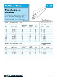
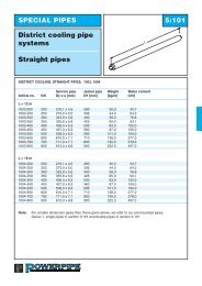
DOUBLE PIPES 4:101Straight pipes,st<strong>and</strong>ard<strong>Powerpipe</strong>s Double pipes are layed vertically with theflow pipe installed below the return pipe.Article No. St<strong>and</strong>ard, 12 m: 1503-DN-000-000Article No. St<strong>and</strong>ard, 16 m: 1504-DN-000-000Article No. St<strong>and</strong>ard, 18 m: 1505-DN-000-000PN 16/PN25Regarding heat lossesPlease see chapter 9!ARTICLE NO. STANDARD, 12 m, 1503Transmission capacityΔ T = 50°CService pipe Weight C-CDN Dy x s [mm] DY [mm] [kg/m] [mm] [m/s] [kW]20 26,9 x 2,0 140 6,1 19 0,8 6525 33,7 x 2,3 140 7,1 19 0,8 10032 42,4 x 2,6 160 9,1 19 0,8 18040 48,3 x 2,6 160 9,6 19 0,9 23050 60,3 x 2,9 200 13,1 20 0,9 37065 76,1 x 2,9 225 16,5 20 1,0 70080 88,9 x 3,2 250 20,7 25 1,0 1.000100 114,3 x 3,6 315 30,7 25 1,1 1.800125 139,7 x 3,6 400 41,5 30 1,3 3.300150 168,3 x 4,0 450 51,0 40 1,4 5.000200 219,1 x 4,5 560 76,0 45 1,6 10.000ARTICLE NO. STANDARD, 16 m, 1504Transmission capacityΔ T = 50°CService pipe Weight C-CDN Dy x s [mm] DY [mm] [kg/m] [mm] [m/s] [kW]100 114,3 x 3,6 315 30,7 25 1,1 1.800125 139,7 x 3,6 400 41,5 30 1,3 3.300150 168,3 x 4,0 450 51,0 40 1,4 5.000200 219,1 x 4,5 560 76,0 45 1,6 10.000ARTICLE NO STANDARD, 18 m, 1505Transmission capacityΔ T = 50°CService pipe Weight C-CDN Dy x s [mm] DY [mm] [kg/m] [mm] [m/s] [kW]100 114,3 x 3,6 315 30,7 25 1,1 1.800150 168,3 x 4,0 450 51,0 40 1,4 5.000200 219,1 x 4,5 560 76,0 45 1,6 10.000Edition 2013
DOUBLE PIPES 4:102Straight pipes,double+<strong>Powerpipe</strong>s Double pipes are layed vertically withthe flow pipe installed below the return pipe.Article No. Double+, 12 m: 1603-DN-000-000Article No. Double+, 16 m: 1604-DN-000-000Article No. Double+, 18 m: 1605-DN-000-000PN 16/PN25Regarding heat lossesPlease see chapter 9!ARTICLE NO. DOUBLE+, 12 m, 1603Transmission capacityΔ T = 50°CService pipe Weight C-CDN Dy x s [mm] DY [mm] [kg/m] [mm] [m/s] [kW]20 26,9 x 2,0 160 6,7 19 0,8 6525 33,7 x 2,3 160 7,8 19 0,8 10032 42,4 x 2,6 180 9,9 19 0,8 18040 48,3 x 2,6 180 10,3 19 0,9 23050 60,3 x 2,9 225 14,0 20 0,9 37065 76,1 x 2,9 250 17,6 20 1,0 70080 88,9 x 3,2 280 22,8 25 1,0 1.000100 114,3 x 3,6 355 33,9 25 1,1 1.800125 139,7 x 3,6 450 46,3 30 1,3 3.300150 168,3 x 4,0 500 56,5 40 1,4 5.000ARTICLE NO. DOUBLE+, 16 m, 1604Transmission capacityΔ T = 50°CService pipe Weight C-CDN Dy x s [mm] DY [mm] [kg/m] [mm] [m/s] [kW]100 114,3 x 3,6 355 33,9 25 1,1 1.800125 139,7 x 3,6 450 46,3 30 1,3 3.300150 168,3 x 4,0 500 56,5 40 1,4 5.000ARTICLE NO. DOUBLE+, 18 m, 1605Transmission capacityΔ T = 50°CService pipe Weight C-CDN Dy x s [mm] DY [mm] [kg/m] [mm] [m/s] [kW]100 114,3 x 3,6 355 33,9 25 1,1 1.800150 168,3 x 4,0 500 56,5 40 1,4 5.000200 219,1 x 4,5 630 82,9 45 1,6 10.000Edition 2013
DOUBLE PIPES 4:103Straight pipes,double++<strong>Powerpipe</strong>s Double pipes are layed vertically withthe flow pipe installed below the return pipe.Article No. Double++, 12 m: 1603-DN-000-000Article No. Double++, 16 m: 1604-DN-000-000Article No. Double++, 18 m: 1605-DN-000-000PN 16/PN25Regarding heat lossesPlease see chapter 9!ARTICLE NO. DOUBLE++, 12 m, 1703Transmission capacityΔ T = 50°CService pipe Weight C-CDN Dy x s [mm] DY [mm] [kg/m] [mm] [m/s] [kW]20 26,9 x 2,0 180 7,4 19 0,8 6525 33,7 x 2,3 180 8,5 19 0,8 10032 42,4 x 2,6 200 10,6 19 0,8 18040 48,3 x 2,6 200 11,1 19 0,9 23050 60,3 x 2,9 250 15,1 20 0,9 37065 76,1 x 2,9 280 19,7 20 1,0 70080 88,9 x 3,2 315 24,9 25 1,0 1.000100 114,3 x 3,6 400 37,8 25 1,1 1.800125 139,7 x 3,6 500 51,8 30 1,3 3.300150 168,3 x 4,0 560 63,7 40 1,4 5.000200 219,1 x 4,5 710 91,2 45 1,6 10.000ARTICLE NO. DOUBLE++, 16 m, 1704Transmission capacityΔ T = 50°CService pipe Weight C-CDN Dy x s [mm] DY [mm] [kg/m] [mm] [m/s] [kW]100 114,3 x 3,6 400 37,8 25 1,1 1.800125 139,7 x 3,6 500 51,8 30 1,3 3.300150 168,3 x 4,0 560 63,7 40 1,4 5.000200 219,1 x 4,5 710 91,2 45 1,6 10.000ARTICLE NO DUBBEL++, 18 m, 1705Transmission capacityΔ T = 50°CService pipe Weight C-CDN Dy x s [mm] DY [mm] [kg/m] [mm] [m/s] [kW]100 114,3 x 3,6 400 37,8 25 1,1 1.800150 168,3 x 4,0 560 63,7 40 1,4 5.000200 219,1 x 4,5 710 91,2 45 1,6 10.000Edition 2013
DOUBLE PIPES 4:104Straight pipes forcut-to-lengthPN 16/PN25Cut-to-lengthKapzonervarannan metersections are everysecond metre.Cut-to-length pipes are manufactured in all dimensions, as given in section 4:101. In these pipes the steelservice pipe is covered by a plastic foil every second metre along the entire pipe length. This arrangementallows easy removal of the foam from the steel in the sections. These sections of the pipe are indicated onthe outside casing pipe. Whole lengths or parts of pipes cut-to-length can be installed at any place in a districtheating distribution system.ARTICLE NO. 1513, 1613, 1713 (12m)L = 12 mArticle No.1513-DN-000-000 (STANDARD)1613-DN-000-000 (DOUBLE+)1713-DN-000-000 (DOUBLE++)L = 16 mArticle No.1514-DN-000-000 (STANDARD)1614-DN-000-000 (DOUBLE+)1714-DN-000-000 (DOUBLE++)L = 18 mArticle No.1515-DN-000-000 (STANDARD)1615-DN-000-000 (DOUBLE+)1715-DN-000-000 (DOUBLE++)An example of how to order:Cut- to-length pipe Double pipe St<strong>and</strong>ard DN 2*100,has Article No. 1513-100-000-000.For measurement details, please seestraight pipes!Pipes are available with «center cut»Above should be indicated in a separateline of text.Edition 2013
DOUBLE PIPES 4:105Curved pipesDeflectionPN 16/PN25ARTICLE NO. 1523, 1623, 1723 (12 m)ARTICLE NO. 1524, 1624, 1724 (16 m)Double pipeMax. deflectionDN L = 12 m L= 16 m Anm.25 - 65 30° To be bent at installation site50 - 80 30° Bent at <strong>Powerpipe</strong> works100 30° 20° Bent at <strong>Powerpipe</strong> works125 - 150 30° 25° Bent at <strong>Powerpipe</strong> works200 25° 32° Bent at <strong>Powerpipe</strong> worksAccuracy of manufacture DN 2*80 - 2*200 +/- 2°Steel service pipeIn the manufacturing of curved pipes welded steel pipes are used.For manufacturing reasons alarm wires are placed in the neutral position.Article No..1523-DN-xxx-000 (STANDARD)1623-DN-xxx-000 (DOUBLE+)xxx = degreesAn example of how to order:Curved Double pipe L = 12m with dim DN 2*100 curved 15°, st<strong>and</strong>ard,has Article No. 1523-100-015-000.Deflection shall be stated in a separate line of text.Edition 2013
DOUBLE PIPES 4:106Curved pipesDeflection versusdesign radiusDesign radiusLengthDeflectionPN 16/PN25CORRELATION BETWEEN DEFLECTION AND DESIGN RADIUSDesign radiusDesign radiusDeflection L = 12 m Deflection L = 12 m1° 690 21° 33,02° 345 22° 31,03° 230 23° 30,04° 170 24° 29,05° 140 25° 28,06° 115 26° 27,07° 98 27° 26,08° 86 28° 25,09° 76 29° 24,010° 69 30° 23,211° 62 31° 22,512° 57 32° 21,813° 53 33° 21,114° 49 34° 20,515 o 46 35° 20,016° 43 36° 19,417° 40 37° 18,918° 38 38° 18,419° 36 39° 18,020° 34 40° 17,5The pipes cannot be bent along its entire length. At each pipe end a straight part will remain,which shall be approximately 2 meters in length.This deviation from an ideal curved pipe radius is to be compensated when installing the pipeby making the pipe trench approximately wider at center.The widening should be ~200 mm at deviation < 10 oThe widening should be ~500 mm at deviation > 10 oEdition 2013
DOUBLE PIPES 4:107Curved pipesElastic radiusDesign radiusLengthDeflectionPN 16/PN25ELASTIC RADIUSDimension Elastic radius Deflection/m12 m25 15 45°40 21 31°50 27 25°65 34 20°80 40 17°100 52 13°125 63 11°150 76 9°200 98 7°The above table shows the elastic radius which is the maximum radius ordeflection that can be allowed without permanent deformation in the steel pipe.Edition 2013
DOUBLE PIPES 4:201BendHorizontalPN 16/PN25ARTICLE NO. 2500, 2600, 2700STANDARD DOUBLE+ DOUBLE++2500 2600 2700Service pipe Jacket pipe Jacket pipe Jacket pipe LDN Dy x s [mm] DY [mm] DY [mm] DY [mm] [mm]20 26,9 x 2,0 140 160 180 100025 33,7 x 2,3 140 160 180 100032 42,4 x 2,6 160 180 200 100040 48,3 x 2,6 160 180 200 100050 60,3 x 2,9 200 225 250 100065 76,1 x 2,9 225 250 280 100080 88,9 x 3,2 250 280 315 1000100 114,3 x 3,6 315 355 400 1000125 139,7 x 3,6 400 450 500 1000150 168,3 x 4,0 450 500 560 1000200 219,1 x 4,5 560 630 710 1000Bends are, as st<strong>and</strong>ard, available as 90 o <strong>and</strong> 45 o .Bends having other degrees such as 75 o , 60 o , 30 o <strong>and</strong> 15 o <strong>and</strong> bends having leg lengths other thanspecified in the above table can be delivered on special request.Article No..2500-DN-degree of bend-000 (STANDARD)2600-DN-degree of bend-000 (DOUBLE+)2700-DN-degree of bend-000 (DOUBLE++)Space for sleeveIn order to adequately fit sleeveInstallation of DN2*50 –2*125 anExtended shank 1200 x 1200 mmis offered. State suffix: 999An example of how to order:Bend Double pipe St<strong>and</strong>ard dim DN 2*80, 90°has Article No. 2500-080-900-000.Edition 2013
DOUBLE PIPES 4:202Termination bend, 90 overtical1500Can be ordered with end cap.1500PN 16/PN25TERMINATION BEND 2510, 2610, 2710 STANDARD DOUBLE+ DOUBLE++2510 2610 2710Service pipe Service pipe Service pipe Service pipeDN Dy x s [mm] Dy [mm] Dy [mm] Dy [mm20 26,9 x 2,0 140 160 18025 33,7 x 2,3 140 160 18032 42,4 x 2,6 160 180 20040 48,3 x 2,6 160 180 20050 60,3 x 2,9 200 225 25065 76,1 x 2,9 225 250 28080 88,9 x 3,2 250 280 315100 114,3 x 3,6 315 355 400125 139,7 x 3,6 400 450 500150 168,3 x 4,0 450 500 560The termination bend is also available in versions with the upward rise of 90 °, see figure below!Termination bend 90 o , with another leg length <strong>and</strong> other degree of bend can be supplied on request.Article No.2510-DN-000-000 (STANDARD)2610-DN-000-000 (DOUBLE+)2710-DN-000-000 (DOUBLE++)Can be ordered with end cap. (State suffix -811)Pipe under - right prefix 032Pipe under - left prefix 031An example of how to order:Termination bend Double St<strong>and</strong>ard pipe with dim DN2*50, st<strong>and</strong>ard design under - rise righthas Article No. 2510-050-000-032.Keep the plastic emballage onduring installation!-000 -032 -031pipe under- pipe underrightleftEdition 2013
DOUBLE PIPES 4:203Termination bend forFacade adaptering,DN 20-25650PN 16/PN251500ARTIKEL NO 2540, 2640, 2740St<strong>and</strong>ard Double+ Double++Service pipe 2540 2640 2740DN Dy x s [mm] Jacket pipe Dy [mm] Jacket pipe Dy [mm] Jacket pipe Dy [mm]20 26,9 x 2,0 140 160 18025 33,7 x 2,3 140 160 180Termination bend designed for façade installation comes with DN 20 valve <strong>and</strong> extended neck.Red h<strong>and</strong>les are adaptered on the front line, blue on the return line.Termination bend can be delivered with exteded length of bend length - max 7 m.Available in angled design.Article No..2540-DN-000-000 (STANDARD)2640-DN-000-000 (DOUBLE+)2740-DN-000-000 (DOUBLE++)An example of how to order:Termination bend for facade installation, DN25 withh<strong>and</strong>le right has Article No. 2540-025-000-032.– 031H<strong>and</strong>le left– 032H<strong>and</strong>le rightNOTE: The valves must beoperated at least twice a year toensure proper function.Edition 2013
DOUBLE PIPES 4:204Profile bendPN 16/PN25PROFILE BEND 2520, 2620, 2720 STANDARD DOUBLE+ DOUBLE++2520 2620 2720Service pipe Jacket pipe Jacket pipe Jacket pipeDN Dy x s [mm] Dy [mm] Dy [mm] Dy [mm]25 33,7 x 2,3 140 160 18032 42,4 x 2,6 160 180 20040 48,3 x 2,6 160 180 20050 60,3 x 2,9 200 225 25065 76,1 x 2,9 225 250 28080 88,9 x 3,2 250 280 315100 114,3 x 3,6 315 355 400125 139,7 x 3,6 400 450 500150 168,3 x 4,0 450 500 560200 219,1 x 4,5 560Bend can be obtained by any angle.Article No.2520-DN-xxx-000 (STANDARD)2620-DN-xxx-000 (DOUBLE+)2720-DN-xxx0-000 (DOUBLE++)xxx = degreesAn example of how to order:Profile bend Dobule pipe with dim DN 2*80, angle 8 ohas Article No. 2520-080-008-000.Edition 2013
DOUBLE PIPES 4:205Bend out of planeL90 o degree bend out of plane to cover changes indirection in profile.LPN 16/PN25ARTICLE NO. 2510, 2610, 2710STANDARD DOUBLE+ DOUBLE++2510 2610 2710Service pipe Jacket pipe Jacket pipe Jacket pipe L x LDN Dy x s [mm] DY [mm] DY [mm] DY [mm] [mm]25 33,7 x 2,3 140 160 180 1000 x 100032 42,4 x 2,6 160 180 200 1000 x 100040 48,3 x 2,6 160 180 200 1000 x 100050 60,3 x 2,9 200 225 250 1000 x 100065 76,1 x 2,9 225 250 280 1000 x 100080 88,9 x 3,2 250 280 315 1000 x 1000100 114,3 x 3,6 315 355 400 1000 x 1000125 139,7 x 3,6 400 450 500 1000 x 1000150 168,3 x 4,0 450 500 560 1200 x 1200200 219,1 x 4,5 560 1200 x 1200St<strong>and</strong>ard degree of bendhorisontally is 90°Angle in profile is optional.α o 3 5 7,5 10 12,5 15 20 25h(mm) 50 90 180 170 215 260 240 420Article No..2510-DN-000-0322510-DN-000-0312610-DN-000-0322610-DN-000-0312710-DN-000-0322710-DN-000-031STANDARD, Right h<strong>and</strong> designSTANDARD, Left h<strong>and</strong> designDOUBLE+, Right h<strong>and</strong> designDOUBLE+, Left h<strong>and</strong> designDOUBLE++, Right h<strong>and</strong> designDOUBLE++, Left h<strong>and</strong> designAn example of how to order:Bend Double pipe with dim DN 2*80, 90° , st<strong>and</strong>ard, right h<strong>and</strong> designhas Article No. 2510-080-000-032.Angle of deflection has to be written in a separate text line.Edition 2013
DOUBLE PIPES 4:301T-pieceL1<strong>Powerpipe</strong> T-pieces are as st<strong>and</strong>ard delivered ina reinforced design, increased thickness <strong>and</strong>,if necessary, increased steel quality.Branch can be installed without dischargingdog leg.PN 16/PN25L2ARTICLE NO. 3510, 3610, 3710STANDARD DOUBLE+ DOUBLE++3510 3610 3710Main pipe Branch pipe L1 L2 Jacket pipe Jacket pipe Jacket pipeDN DN [mm] [mm] DN Dy [mm] Dy [mm] Dy [mm]25-200 25-125 1500 700 25 140 160 180200 150 1600 700 32 160 180 200200 200 1600 800 40 160 180 20050 200 225 25065 225 250 28080 250 280 315100 315 355 400125 400 450 500150 450 500 560200 560The branch pipe cannot be designed in dimensions bigger than the main pipe.Article No..3510-DN main pipe -DN branch pipe-000 (St<strong>and</strong>ard)3610-DN main pipe -DN branch pipe-000 (Double+)3610-DN main pipe -DN branch pipe-000 (Double++)An example of how to order:T-piece Double pipe with main pipe DN 2*100, st<strong>and</strong>ard,<strong>and</strong> branch pipe DN 2*50, has Article No. 3510-100-050-000.Alt. (extended T-piece) has Article No. 3510-100-050-999Space for sleeveIn order to adequately fit sleeve whenInstalling T-piece, we offer a versionwith extension:L1- dimension by 200 mm.L2- dimension by 1.000 mm.State suffix: 999.Edition 2013
DOUBLE PIPES 4:302Intersection unit1200T-pieces are as st<strong>and</strong>ard delivered in a reinforceddesign, increased thickness <strong>and</strong>,if necessary,increased steel quality. Branch can be installedwithout discharging dog leg.550200PN 16/PN25550ARTICLE NO. 3570, 3670, 3770STANDARD DOUBLE+ DOUBLE++3570 3670 3770Main pipe Branch pipe Jacket pipe Jacket pipe Jacket pipeDN DN DN Dy [mm] Dy [mm] Dy [mm]25-200 25-65 25 140 160 18032 160 180 20040 160 180 20050 200 225 25065 225 250 28080 250 280 315100 315 355 400125 400 450 500150 450 500 560200 560The branch pipe cannot be designed in dimensions larger than the main pipe.<strong>Powerpipe</strong> can on request deliver T-pieces in a non reinforced design.Article No.3570-DN main pipe-DN branch pipe-000 (STANDARD)3670-DN main pipe-DN branch pipe-000 (DOUBLE+)3770-DN main pipe-DN branch pipe-000 (DOUBLE++)An example of how to order:Intersection unit with main pipeDN 2*65, st<strong>and</strong>ard, <strong>and</strong> branch pipe DN 2*32has Article No. 3570-065-032-000.Edition 2013
DOUBLE PIPES L2 4:303T-piece with horisontaldeflectionH<strong>Powerpipe</strong> T-pieces are as st<strong>and</strong>ard delivered in areinforced design <strong>and</strong> if necessary with increasedsteel quality.Must be installed with discharging dog leg.L1PN 16/PN25ARTICLE NO. 3510, 3610, 3710STANDARD DOUBLE+ DOUBLE+3510 3610 3710Main pipe Branch pipe L1 L2 Jacket pipe Jacket pipe Jacket pipeDN DN [mm] [mm] DN Dy [mm] Dy [mm] Dy [mm]25-100 25-100 1200 1000 25 140 160 18032 160 180 20040 160 180 200125-200 25-100 1200 1200 50 200 225 250125-200 125-200 1500 1500 65 225 250 28080 250 280 315100 315 355 400125 400 450 500150 450 500 560200 560H= Dy main pipe + 50 mm.The branch pipe cannot be designed in dimensions bigger than the main pipe.NOTE! The branch pipe on the T-piece out of plane will need a discharging dog leg.Article No..3510-DN main pipe-DN branch pipe-238 (STANDARD)3610-DN main pipe-DN branch pipe-238 (DOUBLE+)3710-DN main pipe-DN branch pipe-238 (DOUBLE++)An example of how to order:T-piece Double pipewith main pipe DN 2*100, st<strong>and</strong>ard, <strong>and</strong> branch pipe DN 2*50,has Article No. 3510-100-050-238.Edition 2013
DOUBLE PIPES 4:304T-piece Double/singleL1<strong>Powerpipe</strong> T-pieces are as st<strong>and</strong>ard delivered in areinforced design <strong>and</strong> if necessary with increasedsteel quality.Branch pipe can be installed without dischargingdog leg.c/c700PN 16/PN25ARTICLE NO. 3520, 3620, 3720Main pipe Branch pipe L1 Branch pipe c/cDN [mm] [mm]DN 2*25-200 DN20-80 1500 20 31025 31032 32540 32550 34065 36080 380As st<strong>and</strong>ard the branch pipe is insulated according to <strong>Series</strong> 2.Article No..3520-DN main pipe-DN branch pipe-000 (STANDARD)3620-DN main pipe-DN branch pipe-000 (DOUBLE+)3720-DN main pipe-DN branch pipe-000 (DOUBLE++)An example of how to order:T-piece Double/single st<strong>and</strong>ard design with main pipe DN 2*65 <strong>and</strong>branch pipe DN 25 (<strong>Series</strong> 2) has Article No. 3520-065-025-000Right 032Left 031Edition 2013
DOUBLE PIPES 4:305Transition unit singledoublepipe, knee type1100LC-CPN 16/PN25Type 031ARTICLE NO. 1580, 1680, 1780Dim C-C L L2DN [mm] [mm] [mm]25 265 1410 70032 280 1430 70040 280 1430 70050 295 1440 70065 315 1460 70080 335 1480 700100 430 1575 700125 460 1600 700150 535 1630 700200 615 1705 900NOTE! This solution is not designed to absorb axial forces or movements from single pipes.As st<strong>and</strong>ard branches for single pipes are delivered in <strong>Series</strong> 2 for 1580, 1680 = S3, 1780 = S4.F = Flow (marked with a white dot on the steel pipe).R = ReturnArticle No..1580-DN-000-031 (STANDARD)1580-DN-000-032 (STANDARD)1680-DN-000-031 (DOUBLE+)1680-DN-000-032 (DOUBLE+)1780-DN-000-031 (DOUBLE++)1780-DN-000-032 (DOUBLE++)An example of how to order:Transition unit DN 50, st<strong>and</strong>ard,right h<strong>and</strong> flow has Article No.1580-050-000-032.Left h<strong>and</strong> flowwith flowpipe under031Right h<strong>and</strong> flowwith flowpipe under032Edition 2013
DOUBLE PIPES 4:306Transition unit single –double pipe,straight typeLCan be used between single <strong>and</strong> double pipes atbig expansion forces.PN 16/PN25c/cRight h<strong>and</strong> flowtype 032ARTICLE NO. 1590, 1690, 1790C-C LDN [mm] [mm]25 270 197332 280 197140 280 197150 305 196665 330 196680 360 1962100 425 1955125 530 2500150 570 2500200 710 2500Branches for single pipe are delivered 1590 in <strong>Series</strong> 2. 1690 = S3, 1790 = S4Article No..1590 DN main pipe-000-032 right h<strong>and</strong> flow STANDARD1590 DN main pipe-000-031 left h<strong>and</strong> flow STANDARD1690 DN main pipe-000-032 right h<strong>and</strong> flow DOUBLE+ 0311690 DN main pipe-000-031 left h<strong>and</strong> flow DOUBLE+RF1790 DN main pipe-000-032 right h<strong>and</strong> flow DOUBLE++ 0321790 DN main pipe-000-031 left h<strong>and</strong> flow DOUBLE++RFAn example of how to order:Transition unit single-double pipe, straight,DN 50, st<strong>and</strong>ard, left h<strong>and</strong> flow hasArticle No. 1590-050-000-031.FRRLeft h<strong>and</strong> flowFlowpipe under031FRight h<strong>and</strong> flowFlowpipe under032Edition 2013
DOUBLE PIPES 4:401Preinsulated valvesDpHThe unit consists of a maintenance free ball valve ina fully welded housing together with a corrosion freeball. All valves according to EN448 are supplied tost<strong>and</strong> the yield strength as the pipe line.LThe alarmwire are linked through the stainless steelDPN 16/PN25ARTICLE NO. 4500, 4600, 4700STANDARD DOUBLE+ DOUBLE++4500 4600 4700Service Jacket Jacket Jacket L H Dp Wrenchpipe 2 pc pipe pipe pipe sizeDN Dy x s [mm] DY [mm] DY [mm] DY [mm] [mm] [mm] [mm] [mm]25 33,7 x 2,3 140 160 180 2300 409 150 1932 42,4 x 2,6 160 180 200 2300 422 170 1940 48,3 x 2,6 160 180 200 2300 435 170 1950 60,3 x 2,9 200 225 250 2400 451 190 1965 76,1 x 2,9 225 250 280 2400 463 190 1980 88,9 x 3,2 250 280 315 2600 483 190 19100 114,3 x 3,6 315 355 400 2800 519 235 27125 139,7 x 3,6 400 455 500 3200 540 235 27150 168,3 x 4,0 450 500 560 3400 578 295 27200 219,1 x 4,5 560 3600 652 295 50AdapterforT-keyAdapter forportablelgearThe valve is protected by a hut of stainless steel as a st<strong>and</strong>ard. Please see 8:102Article No..4500-DN-000-000 (STANDARD)4600-DN-000-000 (DOUBLE+)4700-DN-000-000 (DOUBLE++)An example of how to order:Preinsulated valve for main pipe dim DN 2*100, st<strong>and</strong>ardhas Article No. 4500-100-000-000.Please observe: the included ballvalve has to be operated at leasttwice/ year in order to ensure agood function.Please observe: Do not refill abovethe sealing.The sealing shall not be belowwater table continously.Edition 2013
DOUBLE PIPES 4:402BValve unit,CompactHL 1L 2PN 16/PN25Right h<strong>and</strong> outletARTICLE NO. 4570, 4670, 4770DN St<strong>and</strong>ard Double+ Double++ H H B L1 L24570 4670 4770 St<strong>and</strong>ard MinService pipe Dy[mm] Dy[mm] [mm] [mm] [mm] [mm] [mm]Dy[mm]25 140 160 180 480 190 400 800 50040 160 180 200 495 200 450 920 70550 200 225 250 500 210 450 1020 725The drainage pipe is manufactured in stainless steel.Article No..4570-DN-000-000 (STANDARD)Right h<strong>and</strong> outlet has prefix 032Left h<strong>and</strong> outlet has prefix 031.Valve unit with minimal stem height specifies separately.An example of how to order:Valve unit, compact, right h<strong>and</strong> outlet st<strong>and</strong>arddesign dim DN50 has Article No. 4570-050-000-032.Right h<strong>and</strong> outletPlease observe: the included ballvalve has to be operated at leasttwice/ year in order to ensure agood function.Please observe: Do not refill abovethe sealing.The sealing should not be lying underwater continously.Edition 2013
DOUBLE PIPES 4:4031500BValve unit, directThe unit can be used as both drainage <strong>and</strong>air release.HL1The alarmwire are linked through the stainlesssteel.DyPN 16/PN25ARTICLE NO. 4575, 4675, 4775STANDARD DOUBLE+ DOUBLE++4575 4675 4775Jacket pipe Jacket pipe Jacket pipe L1 DN Wrench size B HDN Dy x s [mm] DY [mm] DY [mm] DY [mm] [mm] Out [mm] [mm] [mm]40 48,3 x 2,6 160 180 200 550 25 19 295 48050 60,3 x 2,9 200 225 250 555 25 19 295 48065 76,1 x 2,9 225 250 280 565 25 19 295 48080 88,9 x 3,2 250 280 315 640 32 19 295 485100 114,3 x 3,6 315 355 400 720 40 27 295 485125 139,9 x 3,6 400 450 500 720 40 27 315 485150 168,3 x 4,0 450 500 560 720 40 27 315 485Article No.4575-DN main pipe-000-000 (STANDARD)4675-DN main pipe-000-000 (DOUBLE+)4775-DN main pipe-000-000 (DOUBLE++)An example of how to order:Valve unit left, double pipe st<strong>and</strong>ard withDim DN 2 * 50 (with air realese/drainage DN 25)has Article No. 4575-050-000-000.Please observe: the included ballvalve has to be operated at leasttwice/ year in order to ensure agood function.Please observe: Do not refill abovethe sealing.The sealing shall not be lying underwater continously.Edition 2013
DOUBLE PIPES 4:404200Air release/ drainageBDYThe alarmwires are linked outside the sealing.H1200PN 16/PN25ARTICLE NO. 3540, 3640, 3740STANDARD DOUBLE+ DOUBLE++3540 3640 3740Main pipe Service Jacket Jacket Jacket H Air release/ B-pipe 2 pc pipe pipe pipe drainage measureDN Dy x s [mm] DY [mm] DY [mm] DY [mm] [mm] DN [mm]25 33,7 x 2,3 140 160 180 437 25 11032 42,4 x 2,6 160 180 200 445 40 11040 48,3 x 2,6 160 180 200 451 50 12550 60,3 x 2,9 200 225 250 463 65 14065 76,1 x 2,9 225 250 280 47980 88,9 x 3,2 250 280 315 495100 114,3 x 3,6 315 355 400 520125 139,7 x 3,6 400 450 500 548150 168,3 x 4,0 450 500 560 581200 219,1 x 4,5 560 634Air release/ drainage units manufactured in dimensions dim. DN 25, DN 40, DN 50 och DN 65.Air release/ drainage units are delivered with a screwed on plug.The valve is protected by a end cap as a st<strong>and</strong>ard. Please see 8:102Article No..3540-DN main pipe-DN air release-000 (STANDARD)3640-DN main pipe-DN air release-000 (DOUBLE+)3740-DN main pipe-DN air release-000 (DOUBLE++)An example of how to order:Air release unit for main pipe dim DN 2*100, st<strong>and</strong>ard<strong>and</strong> air release unit DN 25, has Article No. 3540-100-025-000.Please observe: the includedball valve has to be operatedat least twice/year in order toensure a good function.Please observe: Do not refillabove the sealing.The sealing should not belying under water continously.Edition 2013
DOUBLE PIPES 4:405Valve unit with air releaseon one or both sidesDDyValve units are delivered in conformance withSwedish District Heating Association's deliveryrequirements <strong>and</strong> EN 488.The alarmwire are linked through the stainlesssteel.PN 16/PN25HLVALVE UNIT WITH AIR RELEASE ON ONE OR BOTH SIDES 4541, 4542, 4641, 4642STANDARD DOUBLE+ DOUBLE++4541, 4542 4641, 4642 4741, 4742Jacket pipe Jacket pipe Jacket pipe L H Dp Wrench sizeDN Dy [mm] Dy [mm] Dy [mm] [mm] [mm] [mm] [mm]40 160 180 200 2300 440 235 1950 200 225 250 2400 451 295 1965 225 250 280 2400 463 295 1980 250 280 315 2600 483 295 19100 315 355 400 2800 519 295 27125 400 450 500 3200 540 340 27150 450 500 560 3400 578 415 27Air release delivered in DN25.Available with pulled-up alarm wiresAir release on one side has Article no 4541Air release on both sides has Article no 4542AdapterforT-keyAdapter forportablelgearArticle No..4541-DN-000-000 (STANDARD) with one air release4542-DN-000-000 (STANDARD) with two air releases4641-DN-000-000 (DOUBLE+) with one air release4642-DN-000-000 (DOUBLE+) with two air releases4741-DN-000-000 (DOUBLE++) with one air release4742-DN-000-000 (DOUBLE++) with two air releasesAn example of how to order:Valve unit with air release on both sides DN 2*80, st<strong>and</strong>ardhas Article No. 4542-080-000-000.Principle sketchPlease observe: the includedball valve has to be operatedat least twice/year in order toensure a good function.Please observe: Do not refillabove the sealing.The sealing should not belying under water continously.Edition 2013
DOUBLE PIPES 4:406Combination valveDouble, double sided415600HL1Valve units are delivered in conformance withSwedish District Heating Association's deliveryrequirements <strong>and</strong> EN 488.The alarmwires are linked through the stainlesssteel.PN 16/PN25DLARTICLE NO. 4845, 4846, 4847STANDARD DOUBLE+ DOUBLE++4845 4846 4847Service Jacket Jacket Jacket L H L1 Dp Wrenchpipe 2 pc pipe pipe pipe sizeDN Dy x s [mm] DY [mm] DY [mm] DY [mm] [mm] [mm] [mm] [mm] [mm]40 48,3 x 2,6 160 180 200 1600 435 700 19 *50 60,3 x 2,9 200 225 250 1700 451 700 230 19 *65 76,1 x 2,9 225 250 280 1700 463 700 230 19 *80 88,9 x 3,2 250 280 315 1900 483 700 230 19 *100 114,3 x 3,6 315 355 400 2150 519 700 230 27 *125 139,7 x 3,6 400 455 500 2200 540 700 230 27 *150 168,3 x 4,0 450 500 560 2550 578 700 27 **200 219,1 x 4,5 560 2600 652 900 50 *** Adapter for T-key** Adapter for portablel gearAir release in DN25The valve is protected by a end cap as a st<strong>and</strong>ard.See page 8:102Article No.4845-DN-000-000 (STANDARD)4846-DN-000-000 (DOUBLE+)4847-DN-000-000 (DOUBLE++)An example of how to order:Combination valve, double pipe st<strong>and</strong>ard design indim DN 2* 100, has Article No.4845-100-000-000.principle sketchPlease observe: the includedball valve has to be operatedat least twice/year in order toensure a good function.Please observe: Do not refillabove the sealing.The sealing shall not be belowwater table continously.Edition 2013
DOUBLE PIPES 4:407Combination valveDouble, double sided415600HL1Valve units are delivered in conformance withSwedish District Heating Association's deliveryrequirements <strong>and</strong> EN 488.The alarmwires are linked through the stainlesssteel.PN 16/PN25DLRight h<strong>and</strong> versionARTICLE NO. 4745, 4746, 4747STANDARD DOUBLE+ DOUBLE++4745 4746 4747Service Jacket Jacket Jacket L H L1 Dp Wrenchpipe 2 pc pipe pipe pipe sizeDN Dy x s [mm] DY [mm] DY [mm] DY [mm] [mm] [mm] [mm] [mm] [mm]40 48,3 x 2,6 160 180 200 1600 435 700 19 *50 60,3 x 2,9 200 225 250 1700 451 700 230 19 *65 76,1 x 2,9 225 250 280 1700 463 700 230 19 *80 88,9 x 3,2 250 280 315 1900 483 700 230 19 *100 114,3 x 3,6 315 355 400 2150 519 700 230 27 *125 139,7 x 3,6 400 455 500 2200 540 700 230 27 *150 168,3 x 4,0 450 500 560 2550 578 700 27 **200 219,1 x 4,5 560 2600 652 900 50 *** Adapter for T-key** Adapter for portablel gearAir release in DN25The valve is protected by a end cap as a st<strong>and</strong>ard.See page 8:102Article No.4745-DN-000-000 (STANDARD)4746-DN-000-000 (DOUBLE+)4747-DN-000-000 (DOUBLE++)Right h<strong>and</strong> version has prefix 032Left h<strong>and</strong> version has prefix 031An example of how to order:Combination valve, double pipe, right h<strong>and</strong> versiondim DN 2* 100, has Article No. 4745-100-000-032.principle sketch,right h<strong>and</strong> version 032 prefixPlease observe: the included ball valvehas to be operated at least twice/yearin order to ensure a good function.Please observe: Do not refill above thesealing.The sealing shall not be below watertable continously.Edition 2013
DOUBLE PIPES 4:408DpHValve unit withprodtected airrelease/drainageThe alarmwires are linked outside the sealing.LDAL2PN 16/PN25ARTICLE NO. 4542, 4642, 4742, in design 635Air release/drainageMain pipe L Dp Air release H Wrench size DN DA L2DN [mm] [mm]DN [mm] [mm] [mm] [mm] [mm]40 1700 230 25 435 19 25 305 30050 1700 230 25 451 1965 1700 230 25 463 1980 1900 230 25 483 19100 2150 230 25 519 27125 2200 230 25 540 27150 2250 230 25 578 27200 2600 25 652 50Adapterfor T-keyAdapterfor portablegearAir release-/drainage valves are equipped with stainless steel screw plugs <strong>and</strong> are available indimensions DN 25.Connections can be made in the threaded end.Valve stems are facing upwards. Delivered with the same dimensions on both air release /drainage valves.The valve is supplied with end cap for spindle as st<strong>and</strong>ard.See page 8:102An example of how to order:Ventil series 2 with main pipe DN 2*100<strong>and</strong> air release DN 25 in 635 design,has Article No.4542-100-025-635.principle sketchPlease observe: the included ball valve has to beoperated at least twice/year in order to ensure agood function.Please observe: Do not refill above the sealing.The sealing shall not be below water tablecontinously.Edition 2013
DOUBLE PIPES 4:501Fixed pipe sectionPipe lines installed with double pipes which are notterminated by a bend, transition unit, valve orT-piece shall be completed with a fixed pipe sectionbefore pre-heating/ commissioning of the pipe line.Alternatively, steel pipes fixed with fixplatesaccording to the manufacturer's instructions.PN 16/PN25FIXED PIPE SECTION 1520, 1620STANDARD DOUBLE+ DOUBLE++1520 1620 1720Jacket pipe Jacket pipe Jacket pipeDN Dy [mm] Dy [mm] Dy [mm]25 140 160 18032 160 180 20040 160 180 20050 200 225 25065 225 250 28080 250 280 315100 315 355 400125 400 450 500150 450 500 560200 560Article No..1520-DN-000-000 (STANDARD)1620-DN-000-000 (DOUBLE+)1720-DN-000-000 (DOUBLE++)An example of how to order:Fixed pipe section for a main Double pipe DN 2 x 50, st<strong>and</strong>ard has Article No. 1520-050-000-000.Edition 2013
DOUBLE PIPES 4:502Anchor unittThe anchor unit is designed for casting intoconcrete. Dimensioning pressure forcein concrete 5 MN/ m 2 (50 kg/ cm 2 ), st<strong>and</strong>ard valuein ground 0,15 MN/ m 2 (1,5 kg/ cm 2 ), st<strong>and</strong>ard value.PN 16/PN25ANCOR UNIT 5500, 5600, 5700DN Max load (kN) A t Pressure area∅ T = 60°C [mm] [mm] [cm 2 ]25 63 250 20 33732 82 300 20 50540 93 300 20 50550 130 300 20 39065 167 350 30 56580 215 400 30 765100 315 450 30 810125 385 550 35 1120150 515 650 40 1720200 750 750 40 1950∅ T is the deviation from the average operating temperature of the pre-insulated pipe line( Tf x Tr ) Tp= flow line temperature2 Tr = return line temperatureArticle No.5500-DN-000-000 ( STANDARD)5600-DN-000-000 (DOUBLE+)5700-DN-000-000 (DOUBLE++)An example of how to order:Anchor unit for DN 2*50, st<strong>and</strong>ard, hasArticle No.5500-050-000-000.Edition 2013
DOUBLE PIPES 4:503Reduction unitAlternatively, the reduction can becarried out in thefield with eccentric steel cones <strong>and</strong> reducer casings.DN1LDN2PN 16/PN25REDUCTION UNIT 1575, 1675, 1775DN1/DN2 DN25 DN32 DN40 DN50 DN65 DN80 DN100 DN125 DN150 Length[mm]32 x 110040 x x 110050 x x 110065 x x 110080 x x 1100100 x x 1100125 x x 1100150 x x 1300200 x x 1300The detail is used at change of dimentsionTable gives the st<strong>and</strong>ard dimension for reduction unit.Article No..1575-DN1-DN2-000 (STANDARD)1675-DN1-DN2-000 (DOUBLE+)1775-DN1-DN2-000 (DOUBLE++)An example of how to order:Reduction unit for pipes DN 2*50 to DN 2*40has Article No. 1575-050-040-000.NOTE:Consult the designer where the reductionhas to be placed <strong>and</strong> what size.Edition 2013
SPECIAL PIPES 5:101District cooling pipesystemsLStraight pipesArticle no.12 m district cooling: 1003-DN-000-00016 m district cooling: 1004-DN-000-000ARTICLE NO. 1003, 1004Service pipe Jacket pipe Weight Water contentDN Dy x s [mm] DY [mm] [kg/m] [l/m]L = 12 m100 114,3 x 3,6 180 12,5 9,0125 139,7 x 3,6 200 15,3 13,8150 168,8 x 4,0 225 20,0 20,2200 219,1 x 4,5 280 30,0 34,7250 273,0 x 5,0 355 42,0 54,3300 323,9 x 5,6 400 58,0 76,8350 355,6 x 5,6 450 65,0 93,1400 406,4 x 6,3 500 83,0 122,0450 457,0 x 6,3 560 87,0 155,0500 508,0 x 6,3 630 101,0 193,0600 610,0 x 7,1 710 138,0 277,0700 711,0 x 7,1 800 190,0 378,0800 813,0 x 8,8 900 222,0 497,0900 914,0 x 10,0 1000 261,0 627,0L = 16 m100 114,3 x 3,6 180 12,5 9,0125 139,7 x 3,6 200 15,3 13,8150 168,8 x 4,0 225 20,0 20,2200 219,1 x 4,5 280 30,0 34,7250 273,0 x 5,0 355 42,0 54,3300 323,9 x 5,6 400 58,0 76,8350 355,6 x 5,6 450 65,0 93,1400 406,4 x 6,3 500 83,0 122,0450 457,0 x 6,3 560 87,0 155,0500 508,0 x 6,3 630 101,0 193,0600 610,0 x 7,1 710 138,0 277,0700 711,0 x 7,1 800 190,0 378,0800 813,0 x 8,8 900 222,0 497,0900 914,0 x 10,0 1000 261,0 627,0NOTE:For smaller dimensionsthan above listed, <strong>Series</strong>1 <strong>and</strong>/or double pipes arerecomended.The pipes can be fittedwith nordic alarm systemsor with Widecos cable 3dcARTICLE N0 2100, 3100, 4100, 5100 mfl.Bends, T-pieces, Anchor points, Curved pipes <strong>and</strong> valves are manufactured in accordance with the implementationof district heating pipes, series 1. See Ch. 3!Article no.2100-DN-degrees-000 (Bends) 3100-DN main pipe-DN branch-000 (T-pieces)4100-DN-000-000 (Valves) 5100-DN-000-000 (Anchor point)Order example: A 90° bend / DN 400/500 has Article No. 2100-400-900-000.Edition 2013
SPECIAL PIPES 5:102District cooling pipesystemsInsulated pressurepipesArticle no. 12 m district cooling: 1903-DN-000-00016 m district cooling: 1904-DN-000-000According EN12001/EN 13244. the free end states when placing order, depending on the welding method onthe service pipeARTIKEL NR 1903, 1904SDR 26/PN6 SDR 17/PN10 SDR11/PN16 <strong>Series</strong> 0 <strong>Series</strong> 1Service pipe Service pipe Service pipe Jacket pipe Jacket pipeDy Pressure *[mm] *[mm] *[mm] DY [mm] DY [mm]pipe20 2,5 909025 2,7 909032 2,0 2,9 909040 2,4 3,7 11011050 3,0 4,6 11011063 2,5 3,8 5,8 12512575 2,9 4,5 6,8 14014090 3,5 5,4 8,2 160160110 4,2 6,6 10,0 180200125 4,8 7,4 11,4 200200140 5,4 8,3 12,7 200225160 6,2 9,5 14,6 225250180 6,9 10,7 16,4 250250200 7,7 11,9 18,2 280315225 8,6 13,4 20,5 280315250 9,6 14,8 22,7 355400280 10,7 16,6 25,4 355400315 12,1 18,7 28,6 400450355 13,6 21,1 32,3 450500400 15,3 23,7 36,4 500560450 17,2 26,7 40,9 560560500 19,1 29,7 45,4 630630560 21,4 33,2 50,8 710710630 24,2 37,4 57,2 710710710 27,2 42,1 64,5 800800800 30,6 47,4 72,6 900900900 34,4 53,3 81,7 10001000*Wall thicknessDetails such as bends,T-pieces, valves, etc.Article no. 2900, 3900, 4900 etc.Edition 2013
SPECIAL PIPES 5:201High temperature systemsPipes for transportation of fluids at a temperature exceeding 140 o C<strong>Powerpipe</strong> offers a system for transportation of steam or other fluids at high temperature. The pipe constructionconsists of an inner carrier pipe of steel surrounded by shell of mineral wool. This layer of mineral wool issurrounded by polyurethane foam. An HDPE-pipe is a protective cover for the construction.The quality of the steel pipe shall correspond to the dem<strong>and</strong>s in the Pressure directive <strong>and</strong> other local requirements.Commonly used steel qualities are St 35.8.1 according to DIN1629 (seamless pipes) <strong>and</strong> St 37.8.1according to DIN1626 (welded pipes) or P235 GH/P265 GH according to EN10216/EN10217.<strong>Powerpipe</strong> works with a self developed computerized program for calculation/optimization of the system.Depending on dimension <strong>and</strong> temperature the program calculates thickness of mineral wool <strong>and</strong> polyurethaneinsulations <strong>and</strong> also heat losses <strong>and</strong> amounts of generated condense water in the pipe line.In service situations the steel pipe will slide in the mineral wool sheet. This means that special fixing points <strong>and</strong>expansion joints are needed.A sleeve that can transfer axial forces is needed to eliminate the risk for separation between the jacket pipes attwo pipe components.For above-ground pipelines we can offer spiral welded pipes.Pipes for condensated water are delivered as st<strong>and</strong>ard high temperature pipes or st<strong>and</strong>ard <strong>Powerpipe</strong> districtheating pipes. The pipes are delivered with alarm wires for moisture monitoring.The system consists of:● Insulated pipes● Insulated fittings as bends, T-pieces● Fixpoints● Expansion absorbing units● Connection systems for PEH jacket● Quality assuranceEdition 2013
SPECIAL PIPES 5:202High temperature pipesystems.Straight pipesFor steam <strong>and</strong> other media with temperatureexceeding +140° CARTICLE NO. 1803, 1804PIPES FOR STEAMPreinsulated pipes for temperatures above 140 o CThe steel service pipe is covered with an inside mineral wool insulation layer combined with an outsidepolyurethane insulation.During operation of the high temperature system, the steel service pipe will slide in the mineral wool jacket.For this reason, the system has to be designed with special anchor points <strong>and</strong> expansion devices.Contact Power Pipe <strong>Systems</strong> for further details.Manufactured by special order.Article No.1803-DN-Dy-xxxArticle No.1804-DN-Dy-xxxL = 12 mL = 16 mxxx = steel quality where St 35.8.1 is labelled as 003 / St 37.8.1 is labelled as 004.P235GH is labelled as 479P265GH is labelled as 480In need of other material qualities please consult <strong>Powerpipe</strong>.An example of how to order:Straight pipe DN 65 with outer jacket Ø250 mm <strong>and</strong> steel quality St 37.8.1, 12 mhas Article No. 1803-065-250-004PIPES FOR CONDENSATE WATERPlease see Straight pipes chaper 3!Edition 2013
SPECIAL PIPES 5:203High temperature pipesystems, bendFor steam <strong>and</strong> other fluids with temperaturesexeeding +140 o C. Bends are made with a mineralwooljacket around the service pipe of steel toprovide the pipe greatest ability for movement.ARTICLE NO. 2800 (BEND)Article No.2800-DN-Dy-xxxxxx = steel quality according St 35.8.1 is labelled as 003 / St 37.8.1 term 004.P235GH is labelled as 479P265GH is labelled as 480At need of other steel qualities please contact <strong>Powerpipe</strong>.The length of bend can be adapted to customer requirements.An example of how to order:Bend with steel DN 65 <strong>and</strong> jacket pipe Ø250 mm with steel quality St 37.8.1,has Article No. 2800-065-250-003.ARTICLE NO. 2810 (CONNECTING BEND)Article No.2810-DN-Dy-xxxxxx = steel quality according St 35.8.1 is labelled as 003 / St 37.8.1 term 004.P235GH is labelled as 479P265GH is labelled as 480At need of other steel qualities please contact <strong>Powerpipe</strong>.An example of how to order:Connecting bend with steel DN 100 med PEH Jacket pipe 315 mm with steel quality St 37.8.1has Article No. 2810-100-315-004.PIPES FOR CONDENSAT WATERPlease see Straight pipes chapter 3!Edition 2013
SPECIAL PIPES 5:204High temperature pipesystems, T-pieceFor steam <strong>and</strong> other fluids with temperaturesexeeding +140 o C. Bends are made with a mineralwooljacket around the service pipe of steel toprovide the pipe greatest ability for movement.ARTICLE NO. 3800, 3810, 3830Article No.3800-DN (main pipe)-DN(branch)-xxx3810-DN (main pipe)-DN(branch)-xxx3830-DN (main pipe)-DN(branch)-xxxBranch out of levelParallell branchStraight branchxxx = steel quality according St 35.8.1 is labelled as 003 / St 37.8.1 term 004.P235GH is labelled as 479P265GH is labelled as 480At need of other steel qualities please contact <strong>Powerpipe</strong>.An example of how to order:Straight T-piece with main pipe DN100 <strong>and</strong> branch DN65<strong>and</strong> steel quality St 37.8.1has Article No. 3830-100-065-004.PIPES FOR CONDENSAT WATERPlease see Straight pipes chapter 3!Edition 2013
SPECIAL PIPES 5:205High temperature pipesystems, anchor pointFor steam <strong>and</strong> other fluids with temperaturesexeeding +140 o C, anchor points are made with amineral wool jacket around the service pipe of steel<strong>and</strong> Jacket pipe of PEH.ARTICLE NO. 5800The product is equipped with a steam diffusion barrier along the pipe.Power transmission from pipe to flange is made by small steel elements tominimize the heat transfer to the flange.Article No.5800-DN-Dy-xxxxxx = steel quality according St 35.8.1 is labelled as 003 / St 37.8.1 term 004.P235GH is labelled as 479P265GH is labelled as 480At need of other steel qualities please contact <strong>Powerpipe</strong>.An example of how to order:Anchor point for DN100 <strong>and</strong> jacket pipe Ø315 <strong>and</strong> steel quality St 37.8.1has Article No. 5800-100-315-004.Edition 2013
SPECIAL PIPES 5:301Staight pipes withspiral folded jacketpipeL<strong>Series</strong> 1 <strong>and</strong> <strong>Series</strong> 2ARTICLE NO. 1103, 1203Transmission capacityΔ T = 50°CJacket JacketService pipe <strong>Series</strong> 1 <strong>Series</strong> 2 Weight WaterDN Dy x s [mm] Dy [mm] Dy [mm] [kg/m] content [l/m] [m/s] [kW]L = 12 m25 33.7 x 2.3 100 125 2.6-3.0 0.6 0.8 10032 42.4 x 2.6 100 125 3.4-3.3 1.1 0.8 18040 48.3 x 2.6 100 125 3.7-4.1 1.5 0.9 23050 60.3 x 2.9 125 160 5.2-5.8 2.3 0.9 37065 76.1 x 2.9 160 200 7.0-8.0 3.9 1.0 70080 88.9 x 3.2 160 200 8.4-9.5 5.3 1.0 1.000100 114.3 x 3.6 200 225 12.2-13.2 9.0 1.1 1.800125 139.7 x 3.6 225 250 15.4-16.4 13.8 1.3 3.300150 168.3 x 4.0 250 315 19.8-21.3 20.2 1.4 5.000200 219.1 x 4.5 315 400 28.9-31.0 34.7 1.6 10.000250 273.0 x 5.0 400 450 40.9-44.0 54.3 1.8 18.000300 323.9 x 5.6 450 500 52.9-56.0 76.8 2.0 28.000350 355.6 x 5.6 500 560 60.6-65.0 93.1 2.0 34.000400 406.4 x 6.3 560 630 76.2-83.0 122.0 2.0 45.000Type of material, thickness of material <strong>and</strong> surface treatment of the jacket pipe has to bedefined for each order in a specification.Pipes <strong>and</strong> insulation can be delivered in fire classed performance according to NT FIRE 036,class P1 on dem<strong>and</strong>.Suffix for jacket pipe of spiral folded metal is 323.Article No.1103-DN-000-323.An example of how to order:Straight pipe with spiral foldet jacket pipe, DN 100has Article No. 1103-100-000-323Edition 2013
SPECIAL PIPES 5:302Bend with spiroas jacket pipeL<strong>Series</strong> 1, 2LARTICLE NO. 2100, 2200Service pipe Jacket pipe Jacket pipe LArt.nr. DN Dy x s [mm] <strong>Series</strong> 1 <strong>Series</strong> 2 [mm]<strong>Series</strong> 1 Dy [mm] Dy [mm]2100-025 25 33.7x2.6 100 125 10002100-032 32 42.4x2.6 100 125 10002100-040 40 48.3x2.6 100 125 10002100-050 50 60.3x2.9 125 160 10002100-065 65 76.1x2.9 160 200 10002100-080 80 88.9x3.2 160 200 10002100-100 100 114.3x3.6 200 225 10002100-125 125 139.7x3.6 225 250 10002100-150 150 168.3x4.0 250 315 10002100-200 200 219.1x4.5 315 400 10002100-250 250 273.0x5.0 400 450 13002100-300 300 323.9x5.6 450 500 15002100-350 350 355.6x5.6 500 560 16002100-400 400 406.4x6.3 560 630 1600Type of material, thickness of material <strong>and</strong> surface treatment of the jacket pipe has to bedefined for each order in a specification.Pipes <strong>and</strong> insulation can be delivered in fire classed performance according to NT FIRE 036,class P1 on dem<strong>and</strong>.Suffix for jacket pipe of spiral folded metal is 323.Article No. <strong>Series</strong>12100-DN-deviation-323.Article No. <strong>Series</strong> 22200-DN-deviation-323.An example of how to order:Bend with spiral folded jacket pipe, DN 50, <strong>Series</strong> 2 90°has Article No. 2203-050-090-323Edition 2013
District heating for small houses 5:401General<strong>Powerpipe</strong>´s product line for small house connection is wide <strong>and</strong> gives you greater opportunities to selectunique solutions for each property or project.The prerequisite for the viability of these areas is that investment costs are kept low.Of course this may not be at the expense of quality <strong>and</strong> dependability.The right quality is the Key-wordThe heat losses in relation to its high energy consumption is high, up to 40% in some cases.To obtain as low investment costs <strong>and</strong> heat loss as possible, double pipes are recomended.As the number of joints in the double pipe system is reduced, even the risk of future leaks in the system isminimized.Design of district heating pipes <strong>and</strong> stations are also of great value to lower costs, oversizing costs moneyboth in investment <strong>and</strong> operating costs.Right dimensioning is the Key-wordWe offer several different options to build district heating for small house areas.All types contain Double pipes (supply <strong>and</strong> return in the mantle), as main pipeline.This is to obtain low cost of ground works <strong>and</strong> lower heat losses.In order to reduce both heat losses as temperature losses double pipes with extended insulation(DOUBLE+ or DOUBLE+ +) is often prefered.OptionsWe offer several different options to connect a house from a main pipeline (usually double pipes) in thestreet. The choice of the type controlled by● Dimension● Simplicity when assembling● Size of heat loss● CostWe offer● Flexpipe, copper single pipes 5:502● Flexpipe, copper double pipes 5:502● Flexpipe, steel single pipes 5:503● St<strong>and</strong>ard double pipes Chapter 4● Extra insulated double pipes Chapter 4Edition 2013
District heating for small houses 5:402System requirementsTemperature: Max 120°CPressure: Max 16 bar6 mDesignSee chart for pressure drop calculation 9:101-9:104.Flexible pipes, single <strong>and</strong> double, copperInstallation <strong>and</strong> jointing of service pipe● The system is assembled as a solid system that utilizesthe glowing coppers floating characteristics.Pre-heating of the pipe before insulating / backfilling.For lengths ≥ 6 m, see sketch at page 5:403● The pipes are joined together by use of capillary fittings(EN 1254-1) <strong>and</strong> performed by hard soldering.Capillary fittings with groove may not be used.● Solder parts shall be of reinforced type.● For soldering, a silver-phosphorus-kopparlod according to EN 1044 must be used.● Solder skills is required.● For soldering techniques see SMS 3209.● Otherwise, see District Heating Association's technical regulations for copper pipes in district heatingsystems FVF D: 213thConnecting main pipeMain pipe assumed to be double pipe.● Transition from steel to copper to take place through a transition piece. See accessories 8:106.● In order to protect the connection point from harmful load, expansion opportunity option is made asshown in Figure page 5:403 when L ≥ 6m● Connection to the main pipe including foaming takes place according to Chapter 10 <strong>and</strong> with details,see ex Joints 6:503, 6:504.● Special expansion absorbing details are normally not required.● If the expansion of the main pipeet is expected to be longer than 10 mm, the flexible pipe connectionshall be protected with expansion-absorbing material. See fig 5:404.Flexible pipe, single, steelInstallation <strong>and</strong> jointing of service pipe● The system is assembled as a solid system <strong>and</strong> are mounted cold without any special expansion.absorbing details. Pre-heating of the pipe before insulation / backfill is recomended.●●The service pipe of the branch is welded to the main pipeline. Branch installed between flexible pipe<strong>and</strong> main pipe (alternative st<strong>and</strong>ard steel pipe)Welding skills required.Connection main pipe● Connecting to main pipe including foaming takes place according to Chapter 10 <strong>and</strong> with details,see the ex Joints 6:503 <strong>and</strong> 6:504..● Special expansion absorbing details are required.Edition 2013
Laying of steel- <strong>and</strong> copper pipes 5:403Type drawingsFlexible pipes, copperConnecting of flexible pipes, copper todouble pipeDBxAFlexible pipes, copperCDouble pipeSteel flexx = Min. 50 cm.AConnectionmethodFlexible pipes, copperconnectingBDACCDBEEdition 2013
Laying of steel- <strong>and</strong> copper pipes 5:404Flixible pipeExpansion pillowl > 10 mm1 mMain pipeRelief of flexible pipe at large axial movement.Foundation wallFoundation wallClosing valveGround levelGround levelFlexible pipeBasementmin. 300 mmFlexible pipeBasementLast operationCasting ringClosing valveExamples of insertion of the branch in a basement.Examples of insertion of the branch in a basement.Edition 2013
Trenches <strong>and</strong> backfilling 5:405Trenches <strong>and</strong> backfilling<strong>Powerpipe</strong> flexible pipes has a high strength <strong>and</strong> can withst<strong>and</strong> high loads in terms of pressure, impact<strong>and</strong> abrasion.Lines in the streetTrench depth of the lines in the street can be minimized <strong>and</strong> only respect to the street owners dem<strong>and</strong>s has to betaken. A minimum coverage of 400 mm.Excavated soil can be reused <strong>and</strong> refilled around the pipes. The largest particle size, however is limited to 16 mmat the joint sites <strong>and</strong> to 32 mm around the pipes.Trench width can be minimized to about 20 cm wider than the pipe DY. At each joint point the trench must be madewider to accommodate the installation work. The pipes can even be mounted above ground, to be layed into thetrench later.Service pipesTrench depth is minimized, 400 mm coverage in non-traffic loaded surfaces is sufficient. Warning nets should beplaced 100-200 mm above the pipes to prevent future damage.Excavated soil can be reused <strong>and</strong> refilled around the pipes. Limitations, see above.Trench width is minimized, about 150-200 more.Bushes, stones etc. can be passed without problems.For house connecting, the pipe is bent up from the ground with <strong>Powerpipe</strong> bending tool type B.Connecting to main pipeline is performed with <strong>Powerpipe</strong> T-sleeve, see Chapter 6, Joints.For type sections Flexible pipes, see 5:406.For type sections, solid single <strong>and</strong> double, see 10.2.1.Edition 2013
Type section for flexible pipes 5:406TYPE SECTION FLEXIBLE SINGLE PIPESTYPE SECTION FLEXIBLE DOUBLE PIPESWarning tape/netWarning tape/netTop fillingTop fillingTTSurroundingfilling0-16200Surroundingfilling0-16200Pipe bed8-16100Pipe bedS<strong>and</strong> 8-16100DyDyDyBBAlternatively, pipes can be layed without s<strong>and</strong> directlyon the trench bottom <strong>and</strong> backfilled with stone-freeexisting soil.T = min 600 in street surface.min 400 in non-drivable surface.Dy (mm) B (mm)< 100 350100–150 500150–200 600Alternatively, pipes can be layed without s<strong>and</strong> directlyon the trenchbottom <strong>and</strong> backfilled with stone-freeexisting soil.T = min 600 in street surface.min 400 in non-drivable surface.Dy (mm) B (mm)≤ 150 300> 150 400Depending on the trench method <strong>and</strong> materials thelower requirement B > Dy can be leading.Edition 2013
Flexpipe, copper or steel 5:5011. System descriptionFlexpipe is a flexible pre-insulated pipe systems useful for temperatures up to 120° C. The Pipe is typically usedfor connecting small houses to a larger pre-insulated pipe line who usually is made of steel.The media pipe is made of copper <strong>and</strong> the practical use is very simple. The thermal insulation consists of flexiblepolyurethane insulation with excellent insulating qualities.The flexibility of Flexpipe means it can adapt to virtually any conditions in piping systems without problems.The tubes can pass intersecting lines either above or below. Other barriers can easily be crossed on installation.Flexpipe makes it possible to choose the shortest route without having to take the conventional considerations.Flexpipe is delivered to the constructions site in 100 meter coils. Usually the pipes can be layed withoutbranching in the pipe-trench which therefore can be minimum wide. This means significant cost reductions.Another advantage is that construction time is reduced when using the Flexpipe. The above advantages meanthat Flexpipe is not only an excellent technical solution but also involves both time <strong>and</strong> cost savings.2. Area of use3. SpecificationsCopper pipe:Steel pipe:max 120°C / max 16 barmax 120°C / max 16 bar3.1 Service pipe , copper Glowed copper pipe, R220 EN 1057QualitiesStretch strength 60 kg/m3Number of closedcells >90%Water absorption
Flexpipe, copper 5:502Flexible pipe, copperFlexible pipes for connecting to small housesdelivered on a reel.SINGLEFLEX, COPPER 1366, 1266, 1566, 1567Art.nr. Media- Jacket- Weight Water- Transfer- Bend Deliverypipepipe content capacity radius lengthΔ T = 50°C,Dy x s DY (kg/m) (l/ m) Δ p = 1 mbar/m min m m(mm) (mm) kW1366-022 22x1,0 91x2,2 1,61 0,31 27 0,8 * 1001266-028 28x1,2 91x2,2 1,90 0,51 50 0,8 * 1001266-035*) 35x1,5 91x2,2 2,27 0,83 85 0,8 * 100DOUBLEFLEX COPPER 1566Art.nr. Media- Jacket- Weight Water- Transfer- Bend Deliverypipepipe content capacity radius lengthΔ T = 50°C,Dy x s (mm) DY (mm) (kg/ m) (l/ m) Δ p = 1 mbar/m min m mkW1566-015* ) 2x15x1,0 91x2,2 1,35 2*0,31 9 0,8 * 1001566-018* ) 2x18x1,0 91x2,2 1,50 2*0,20 15 0,8 * 1001566-022 2x22x1,0 91x2,2 1,72 2*0,31 27 0,8 * 1001566-028 2x28x1,2 91x2,2 2,30 2*0,51 50 0,8 * 1001567-018*) 2x18x1.0 113x2,4 1.95 2*0.20 15 1.0 * 1001567-022* ) 2x22x1,0 113x2,4 2,17 2*0,31 27 1,0 * 1001567-028* ) 2x28x1,2 113x2,4 2,75 2*0,51 50 1,0 * 100Flexible pipe has a corrugated outer jack that eases the laying.Flexible pipe is delivered as complete reel (100 m). Delivered length may differ slightly from the ordered length.With regard to heat losses, see 9:203.For mounting the T-piece, see 6:503-6:504.Flexble Pipe, copper, can be delivered with alarm by spesific order of min. 500 m. The alarm wire is flexible. Thealarm function can not be guaranteed after bending.* ) NOTE! These single <strong>and</strong> double flexible pipes can be purchased on special order. Not in stock.An example on how to orderDouble flex, copper 2*22/91 mm has Aricle No. 1566-022-022-000.For more information regarding alarm, etc. consult <strong>Powerpipe</strong>.Edition 2013
Flexpipe, steel 5:503Flexible pipe, steelFlexible pipes for connecting to small housesdelivered on a reel.SINGLEFLEX STEEL 1206, 1306Art.nr. Media- Jacket- Weight Water- Transfer- Bend Deliverypipepipe content capacity radius lengthΔ T = 50°C,Dy x s DY (kg/ m) (l/ m) Δ p = 1 mbar/m min m m(mm) (mm) kW1306-020 20x2,0 91x2,2 1,52 0,2 14 0,8 * 1001206-028 28x2,0 91x2,2 2,23 0,45 40 1,0 * 100Flexible pipe has a corrugated outer jack that eases the laying.Flexible pipe is delivered as complete reel (100 m). Delivered length may differ slightly from the ordered length.With regard to heat losses, see 9:203.For mounting the T-piece, see 6:503-6:504.Flexble Pipe, steel, can be delivered with alarm by spesific order of min. 500 m. The alarm wire is flexible.The alarm function can not be guaranteed after bending.* ) NOTE! These single <strong>and</strong> double flexible pipes can be purchased on special order. Not in stock.An example of how to order:Double flex, copper 2*22/91 mm has Aricle No. 1206-028-000-000.For more information regarding alarm, etc. consult <strong>Powerpipe</strong>.Edition 2013
JOINTS 6:101OverviewWelding jointA welding connection of the Jacket pipe on aDistrict heating pipe means that PEH-materials inthe pipe <strong>and</strong> sleeve are welded together at thetouching surfaces.MaterialRequirementsWelding joint,MittelWelding joint, MittelThe sleeve consists of a slotted sleeve whichare welded to the jacket pipe <strong>and</strong> extruderweldedlongitudinally.● Casing● Welding sleeve● Welding plugsWelding joint,ShrinkableWelding joint, ShrinkThe sleeve consists of a sleeve of PEH thatfirst shrinks against the jacket pipe <strong>and</strong> thenis weldet to the pipe.● Casing● Welding sleeve● Welding plugsLShrinkable casingShringkable casing is a bond between the jacketpipess where the sleeve by shrinkage is joining thejacket pipe <strong>and</strong> produces a seal/power transmission.The seal consists of a layer of mastic between thesleeve <strong>and</strong> the pipe.Double exp<strong>and</strong>ingshrinkablecasingLDouble exp<strong>and</strong>ing PEHThe shrink sleeeve is made of PEH <strong>and</strong>exp<strong>and</strong>ed in two stages.Shrinkable casing, PEH, double sealingThe casing is made of PEH <strong>and</strong> is always fittedwith shrink sleeves as an extra seal <strong>and</strong> arethen called double sealing.● Shrink casing DX● Extra wide masticb<strong>and</strong>● Welding plugs● Fops● Shrink casing DTK● Mastic b<strong>and</strong>● Shrinkablesleeve● Welding plugs● FopsDouble sealingShrinkablecasing, PEXShrinkabel casing, PEXThe casing is made of PEX. This casing canbe used without heat shrink sleeves.● Shrink casing PEX● Mastic b<strong>and</strong>● Welding plugs● FopsLOversized casingOversized casing is a bond between the jacketpipes where the sealing between the casing <strong>and</strong>pipe consists of shrinkable sleeves.Oversized casing are primarily used at lowdsensity requirements. For example indoor,installation in tunnels etc.● Oversized casing● Wedger● Shrinkablesleeve● Welding plugs● FopsOversizedcasingEdition 2013
JOINTS 6:102Electro welded jointMittelLARTICLE NO 6110<strong>Powerpipe</strong> offers a joint made by Mittel <strong>AB</strong>. The method involves a slotted sleeve assembled to the district heatingpipe, which is surrounded by a conductive metal net.Connecting surfaces are welded together under pressure <strong>and</strong> under controlled temperature conditions.Finally, the longitudinal slit is welded together by a specially designed extruder equipment.The joint can be pressure tested before foaming.Can be delivered in different lengths (st<strong>and</strong>ard = 700 mm) used for example for repairs.Joint set, MittelArticle No.Dim PEHjacket pipe [mm]6110-DY jacket pipe 90-1000For dimensions Ø500 <strong>and</strong> bigger the joint is delivered slotted.An example of how to order:Welding joint set, Mittel for DN 500/710 (seies 2)has Aricle No. 6110-710-000-000.Edition 2013
JOINTS 6:103Welding joint,shrinkable700LARTICLE NO 6112<strong>Powerpipe</strong> offers a joint named Welding joint, shrinkable. The method involves a shrinking sleeve assembledto the district heating pipe, which is surrounded by a conductive copper element between sleeve <strong>and</strong> jacketpipe. Connecting surfaces are, after the shrinking process welded together under pressure <strong>and</strong> undercontrolled temperature conditions. The joint can be pressure tested before foaming.Joint set Welding joint, shrinkableArticle No.Dim PEHjacket pipe [mm]6112-DY jacket pipe 225-1000An example of how to order:Welding joint, shrinkable for DN 500/710 (seies 2)has Aricle No. 6112-710-000-000.Edition 2013
JOINTS 6:202Double sealingshrinkable sleeve(kit)700HDPEARTICLE NO 6364Double shrink DTK is a shrinkable sleeve, made of HDPE. A wide sealant mastic strip is placed betweenthe sleeve <strong>and</strong> jacket pipe. Installation is done with a gas torch . The shrinkable sleeve comes withshrink-sleeves <strong>and</strong> therefore the joint is double sealed.The joint is pressure tested after cooling <strong>and</strong> after foam insulation, the foamholes are closed.JOINT SETJacket pipe Shrinkable sleeve Tubular sleeveArticle No. DY [mm] D [mm] Width [mm]6364-090 90 103 1506364-110 110 125 1506364-125 125 140 1506364-140 140 156 1506364-160 160 177 150 shrink sleeve6364-180 180 197 150 tubular6364-200 200 218 1506364-225 225 244 1506364-250 250 269 1506364-280 280 300 1506364-315 315 336 2256364-355 355 377 2256364-400 400 425 2256364-450 450 474 2256364-500 500 530 2256364-560 560 590 2256364-630 630 660 3006364-710 710 749 300 shrink sleeve6364-800 800 838 300 open6364-900 900 949 300Required mastic is supplied separately.Article No.6364 - Dy jacket pipe-000-000 includes two shrink sleeves /tubular sleeves.An example on how to order:Double sealing shrink casing DN 80/180has Aricle No. 6364-180-000-000.For casing in dimensions
JOINTS 6:203Heat-shrinkablesleeve,PEXLARTICLE NO 6362Shrinkable sleeve, PEX is a heat-shrinkable oversized casing constructed of multiple, crosslinked, highdensity polyethylene layers. A wide sealant mastic strip is wrapped around the ends of the pipe under thesleeve. Installation is made with a gas torch <strong>and</strong> due to the crosslinked material, both shrinking behaviour<strong>and</strong> shrink forces are predicted <strong>and</strong> controlled. The shrinkable sleeve can be used in combination withheat-shrinkable tubular casing as additional outside sealing. see 6:401.The joint is recommended to be pressure tested after cooling <strong>and</strong> the holes are welded after foaming.Joint set Heat shrinkable sleeve PEXPEH jacket pipe Sleeve as supplied Max possible shrinkedDY [mm] L[mm] D[mm] D[mm]90 700 103 90110 700 125 110125 700 140 125140 700 156 140160 700 177 160180 700 197 180200 700 218 200225 730 244 212250 730 270 230280 730 300 256315 730 335 285355 730 378 327400 730 425 366450 730 478 413500 730 530 460560 730 592 510630 730 672 592710 730 755 665800 730 845 753900 730 944 851The product is supplied in the kit with separate mastic <strong>and</strong> the required distances.Article No.6362-DY jacket pipe-000-000An example on how to order:Heat shrinkable casing PEX to DN 80/180has Aricle No. 6362-180-000-000.Edition 2013
JOINTS 6:204Double sealingshrinkable sleeve(kit)1400 700HDPEARTICLE NO 6364Double sealing shrinkable sleeve DTK is produced of HDPE. A wide sealant mastic strip is wrapped aroundthe ends of the pipe under the sleeve. Installation is made with a gas torch. The additional use of shrinksleeves make the joint double sealed.The joint is pressure tested after cooling <strong>and</strong> the holes are welded after foaming. Minimal wall tickness onthe casing is 4,5 mm.REPARI KITJacket pipe Shrinkable sleeve Tubular sleeveDY [mm] D [mm] width [mm]90 103 150110 125 150125 140 150140 156 150160 177 150 Tubular sleeve180 197 150200 218 150225 244 150250 269 150280 300 150315 336 225Required mastic is supplied separately.Article No.6364 - Dy jacket pipe-140-000 for repair contains two shrinking sleeves.An example on how to order:Double sealing repair kit to DN 80/180has Aricle No. 6364-180-140-000.Required Extra wide vowen mastic strip: see page 8:301Edition 2013
JOINTS 6:205Double sealedExtended sleeveLFor single use compensator <strong>and</strong> valve (kit)DiDyARTICLE NO 6113The Extended sleeve is produced of HDPE; A wide sealant mastic strip is wrapped around the ends of thepipe under the sleeve. Installation is made with a gas torch. The additional use of shrink sleeves make the jointdouble sealed. The joint is pressure tested after cooling <strong>and</strong> the holes are welded after foaming.DY Di Dy Length (L) Tubular sleeveJacket pipe [mm] Sleeve [mm] [mm] [mm] width [mm]110 125 140 1150 150125 140 160 1150 150140 156 180 1200 150160 177 200 1200 150180 197 225 1250 150200 218 250 1250 150225 244 280 1330 150250 269 315 1400 150280 300 355 1400 150315 336 400 1430 225355 377 450 1430 225400 425 500 1430 225450 474 560 1500 225500 530 637 1500 225560 590 710 1500 225The extended Sleeve is shrinkable at both ends.Required vowen mastic is supplied separately, see page 8:301Extended Sleeve Article No.6113 - DY includes two shrinkable sleeves/tubular sleevesAn example on how to order:Extended sleeve for valve DN 200/355 (Seies 2) has Aricle No. 6113-355-000-000.Edition 2013
JOINTS 6:206Double sealedReduction sleeveLThe reduction sleeve is made of PEH <strong>and</strong> usedto connect two district heating jacket pipes indifferent dim.ARTICLE NO 6124Reduction sleeve is produced of HDPE; A wide sealant mastic strip is wrapped around the ends of the pipeunder the sleeve. Installation is made with a gas torch. The additional use of shrink sleeves make the joint doublesealed. The joint is pressure tested after cooling <strong>and</strong> the holes are welded after foaming.Dimension Sleeve dimension Lengthconnected pipe [mm] D1–D2 [mm] [mm]125 - 110 140 - 125 900140 - 125 156 - 140 900160 - 140 177 - 156 900160 - 140 197 - 177 900200 - 160 218 - 197 900225 - 200 244 - 218 900250 - 225 269 - 244 900280 - 250 300 - 269 900325 - 280 336 - 300 900355 - 315 377 - 336 900400 - 355 485 - 377 900450 - 400 476 - 425 900500 - 450 528 - 476 1100560 - 500 591 - 528 1100630 - 560 663 - 591 1200710 - 630 746 - 663 1200800 - 710 839 - 746 1200Reduction sleeve of multiple step <strong>and</strong> alternative length is manufactured against specific order.Required mastic is supplied separately, see page 8:301.Article No.6124-D1-D2-000 include two shrinkable tubular sleevesAn example on how to order:Reduction sleeve inclusive two tubular sleeves to DN 80/180-65/160has Article no. 6124-180-160-000.Edition 2013
JOINTS 6:207Double sealedTermination sleeve(kit)Termination sleeve is used for closing a districtheating pipelineD700DYARTICLE NO 6134The termination sleeve is produced of HDPE; A wide sealant mastic strip is wrapped around the ends of thepipe under the sleeve. Installation is made with a gas torch. The additional use of shrink sleeves make the jointdouble sealed.The joint is pressure tested after cooling <strong>and</strong> the holes are welded after foaming.The casing can, as an alternative be insulated with halv shells.Jacket pipe DY [mm]Termination sleeve D [mm]110 122125 138140 155160 177180 196200 216225 245250 271280 299315 339355 380400 428450 477500 530560 590630 660710 749800 838900 949Required mastic is supplied separately. Sleeve can be supplied with length = 1100 mm. State suffix 110Article No.6134-DY-000-000 shrinkable termination sleeve including shrinkable sleeve.An example of how to order:Termination sleeve with shrinkable sleeve DN 80/180 has article no.6134-180-000-000.Art.no. 9604-DN steel pipe-thickness of shell-000Extended termination sleevefor off valve has length1100 mmArticle No.6115-DY-000-000Edition 2013
JOINTS 6:208Heat shrinkableflexible joint(kit)LPEXARTICLE NO 6200Flexible joint is a shrinkable flexible sleeve, made of PEX. A wide sealant mastic strip is wrapped around theends of the pipe under the casing. Installation is made with a gas torch <strong>and</strong> due to the crosslinked material,both shrinking behaviour <strong>and</strong> shrink forces are predicted <strong>and</strong> controlled.The powerjoint is pressure tested after cooling <strong>and</strong> the holes are welded after foaming.Double sealed flexible jointPEH jacket pipe Sleeve as supplied Radius steel pipe LengthDY [mm] Di [mm] bend [mm] [mm]90 103 200 980110 125 200 980125 140 200 1050140 156 240 1050160 177 240 1050180 197 240 1050200 218 240 1120225 244 300 1220250 269 380 1340280 345 420 1225315 345 550 1225Double sealed flexible sleeve (kit) are available for <strong>Series</strong> 2 <strong>and</strong> double pipesArticle No.6200 - Dy jacket pipe - DN steel pipe - 000 enkelrör includes steel pipe bend, spacer <strong>and</strong> shrink sleeve.NOTE! For double pipe bend, a fixing plate between the steel pipes is needed.An example on how to order:Flexible joint (kit) for double pipe DN 2 x 40/160 including detailsas above has Article No. 6500-040-160-000.Edition 2013
JOINTS 6:301Tubular <strong>and</strong> openshrinking sleeveTubular sleeveOpen sleeveTUBULAR SHRINKING SLEEVE 6210, OPEN SHRINKING SLEEVE 6240The shrinking sleeves are thick-walled, internally coated with mastic <strong>and</strong> has high tensile strength.Supplied individually wrapped in protective plastic, which protect it from contamination before assembly.The open sleeve is connected with a closural seal. The sleeve is delivered pre cut in a cover.DY DY Width [mm] Width [mm] Shrink ratioJacket pipe Casing Double sealing Other sleeves[mm] [mm] Tubular Open Tubular/Open Tubular* OpenArt. no 6241 Art. no 624090 110 150 225 121/81 25%110 125 150 225 141/93 25%125 140 150 225 156/104 25%140 153 150 225 172/127 25%160 174 150 225 196/153 25%180 193 150 225 215/150 25%200 215 150 225 230/170 25%225 242 150 225 255/190 25%250 267 150 225 300/225 25%280 299 150 225 340/255 25%315 336 225 300 380/285 25%355 377 225 300 405/325 25%400 425 225 225 300 460/360 25%450 477 225 225 300 510/410 25%500 533 225 225 300 565/450 25%560 595 225 225 300 605/490 25%630 666 300 300 25%710 750 300 300 25%800 846 300 300 25%900 947 300 300 25%* Original / shrinked condition D [mm] / D [mm]Tubular shrink sleeve article no. An example of how to order:6210-OD jacket pipe-000-000 Tubular shrink sleeve DN 80/180 has art. no. 6210-180-000-000.Open shrink sleeve article no. An example of how to order6240-OD jacket pipe-000-000 Open shrink sleeveDN 200/400 has art. no. 6240-400-000-000.Edition 2013
JOINTS 6:302End capDYHeat-shrinkable district heating end cap is installedat the pipe end <strong>and</strong> used to protect the thermalinsulation between jacket <strong>and</strong> service pipes.It is coated with an adhesive, specially designedfor performance at high temperature conditions.ARTICLE NO 6291, 6292The end caps are available for jacket pipe dimensions Ø 90–Ø 500Single pipeDouble pipeArticle No. Intervall DI Intervall DY Article No. Intervall DI Intervall DYTo be deliveredTo be delivered6291- 010 30– 10 105– 47 6292-010 12-20 90-1256291- 020 30– 15 140– 75 6292-020 19-34 85-1446291- 030 40– 24 105– 75 6292-030 24-60 105-1606291- 040 55– 24 135– 75 6292-070 24-60 135-2356291- 050 60– 24 148– 756291- 060 60– 30 175–1356291- 070 90– 40 150– 906291- 080 95– 50 195–1306291- 090 145– 68 240–1456291- 100 150– 68 270–1456291- 110 180–120 295–2206291- 120 255–120 360–2206291- 130 280–200 420–3406291- 140 415–200 540–3406291- 150 530–260 650–360Article No.6291 – OD jacket pipe-000-000 for single pipe6292 – OD jacket pipe-000-000 for double pipeAn example of how to order:An end cap for a preinsulated pipe DN 80/180 has Aricle No. 6291-180-080-000.Edition 2013
JOINTS 6:401Hot tapping T-joint with or without a valve<strong>Powerpipe</strong> offers a complete system for installation of hottapping T-joints.Details <strong>and</strong> instructions are available for● 45 o branches Single pipe DN 20 - DN 150● Banches Double pipe DN 20 - DN 100Ordinary 45 o T-jointAll details for hot tapping T-joints are delivered as doublesealing system.The casing to the main pipe is cut in axial direction beforeentering main pipe. The cut in the casing is extruder welded.After shrinking the casing the sleeves are installed.Edition 2013
JOINTS 6:402T-joint forconnecting doublepipe to double pipeD 1D a700D yARTICLE NO 6530T-joint for connecting double pipe to double pipe is a shrinkable sleeve, made of HDPE. A wide masticstrip is placed between the sleeve <strong>and</strong> jacket pipe. Installation is done by extruder welding the split casing<strong>and</strong> shrink withgas torch. Delivered with the required heat shrink tubular/open sleeves.Dy1 = Outer diameter, main pipe in mmDy2 = Outer diameter, branch in mmArticle No.6530-Dy 1 -Dy 2 -000 includes a shrinkable casing, two tubular <strong>and</strong> two open shrinkable sleeves.An example on how to order:joint double-double for the main pipe, two tubular <strong>and</strong> two open shrinkable sleevesDN 2x100/315 <strong>and</strong> branch DN 2x50/200 has Article No. 6530-315-200-000.Edition 2013
JOINTS 6:403T-joint, 45° flexible,for branches≤ OD 140L 1150D 3100200Double sealed typeLARTICLE NO 6540T-joint, 45° flexible is produced of HDPE; A wide sealant mastic strip is wrapped around the ends of the pipeunder the casing. Installation is made with a gas torch. The additional use of shrink sleeves make the jointdouble sealed.The joint is pressure tested after cooling <strong>and</strong> the holes are welded after foaming.Main pipe [mm]Branch jacket [mm]Jacket 75 90 110 125 140 160 180[mm] L 1 D 3 L D 3 L D 3 L D 3 L D 3 L D 3 L D 3 L90 1000 103 690 125 690110 1000 125 690 140 690125 1000 125 690 156 820 156 820140 1000 125 690 156 820 177 820 197 820160 1000 125 690 156 820 177 820 218 820 218 820180 1000 125 690 156 820 177 820 218 820 244 820 218 820200-250 1000 125 690 156 820 177 820 218 820 244 820 269 820280-710 1200 125 690 156 820 177 820 218 820 244 820 269 820OBS! The corrugated pipe requires a carefully performed heating to be flexible.Space available to mount Naval's tapping valve for <strong>Series</strong> 2 <strong>and</strong> <strong>Series</strong> 3.The mounted steel bend radius shall be 5s or greater.c-c measure at drilling should be min. 650 mm.Article No.6540-DY main pipe avstick-000 includes a shrinkable casing <strong>and</strong> two tubular <strong>and</strong> shrinking sleeves.An example of how to order:T-joint, 45°, flexible including two tubular <strong>and</strong> two open shrinkable sleeves for main pipe DN 400/630<strong>and</strong> branch DN 80/180 has article no. 6540-630-180-000.The branch must be at least one DN smaller than the main pipe.Tubular/open shrink sleeve, see 6:302Edition 2013
JOINTS 6:404T-joint, 45° forbranches ≥ OD 160700Dy250Double sealed typeARTICLE NO 6540T-joint 45 o for branches is produced of HDPE; A wide sealant mastic strip is wrapped around the ends of thepipe under the casing. Installation is made with a gas torch. The additional use of shrink sleeves make the jointdouble sealed.The joint is pressure tested after cooling <strong>and</strong> the holes are welded after foaming.JacketBranch jacket [mm]main pipe 225 250 280[mm] Dy [mm] Dy [mm] Dy [mm]225 280250 280280 280 355315 280 355355 - 710 280 355 355Dimensions are adopted to hot tapping valves (Naval) for <strong>Series</strong> 2 <strong>and</strong> <strong>Series</strong> 3.Article No.6540-DY main pipe-Dy branch-000 includs sharinkable main casing, 45 o knee, reduction,three tubular <strong>and</strong> two open shrink sleeves.An example of how to order:T-joint for main pipe DN 400/630 <strong>and</strong> branch DN 200/355has article no. 6540-630-355-000.Please observe:The branch has to be of a smaller dimension than the main pipe.Please see 8:401 regarding need of foaming liquids!Edition 2013
DyJOINTS 6:405Double sealedT-joint for flexiblepipes500DyFor branching from the flexible pipe to flexible pipe.620ARTICLE NO 6540Joint for flexible pipes is a heat shrinkable joint, A wide sealant mastic strip is wrapped around the ends ofthe pipe under the casing. Installation is made with a gas torch. The additional use of shrink sleeves makethe joint double sealed.The joint is pressure tested after cooling <strong>and</strong> the holes are welded after foaming.Article No. Jacket pipe Dy [mm]branch/main pipe [mm]shrinkable6540-090 90 1056540-110 110 125T-joint for flexible pipes is designed for simple assembly of flexible pipes to flexible pipes.NOTE! The corrugated pipe of PEH requires a carefully performed heating to be flexible.Article No.6540-DY main pipe-DY branch-395 includes joint, one tubular shrink sleeve <strong>and</strong> a two open shrink sleeves.An example on how to order:T-joint with main pipe Dy 110 for branch Dy 90 mm has Article No. 6540-110-090-395Edition 2013
JOINTS 6:406T-joint for connectingsingle pipe todouble pipe900600Min. godstjocklek wall thickness 4,5 4,5 mmARTICLE NO 6535T-joint for double/singe pipe is a shrinkable casing made of HDPE. A wide sealant mastic strip is wrappedaround the ends of the pipe under the casing. The splitted main casing is extruder welded <strong>and</strong> shrinked witha gas torch. The additional use of shrink sleeves make the joint double sealed.The joint is pressure tested after cooling <strong>and</strong> the holes are welded after foaming.DN / DY Dy1 Dy branch Dy2 Dy2 (connection) c/cmain pipe [mm] [mm] [mm] [mm] [mm]2 x 25 / 140 174 90 110 125 2602 x 32 / 160 193 90 125 140 2602 x 40 / 160 193 90 140 160 2602 x 50 / 200 242 90 153 180 2602 x 65 / 225 255 90 174 200 3002 x 80 / 250 281 3002 x 100 / 315 348 3002 x 125 / 400 4352 x 150 / 450 5332 x 200 / 560 660If T-sleeves are to be used for connected vale, please indicate this separately.Article no.6535-Dy1-Dy2-000 includes a shrinkable casing, two tubular shrinking sleeves <strong>and</strong>two open shrinking sleeves.An example of how to order:T-joint double/single including 2 tubular <strong>and</strong> 2 open sleeves DN 2x80/250 <strong>and</strong> branch DN 25/90has Article No. 6535-250-090-000.Please observe:The branch has to be of a smaller dimension than the main pipe.Edition 2013
JOINTS 6:407Measure joint400-700Control unit for single pipes600ARTICLE NO 6270Measure joint is used when <strong>and</strong> where you want a simple access to the alarm wires to easily measurefor any errors. Delivered with cap. Branch can be adjusted in hight (400-700 mm).Article No.6270-DY jacket pipe-000-000An example on how to order:Measure joint for DN 300/500 has Article No. 6270-500-000-000200700Insulated alarm wirethat folds downEarth connection300Tubular shrinksleeve700Example how to useEdition 2013
Monitoring systems 7:101Monitoring systemsThe purpose of a moisture monitoring is to detect <strong>and</strong> locatemoisture in the pipe insulation. This provides a cost effective<strong>and</strong> easy to use tool to monitor <strong>and</strong> troubleshoot the pipelinethroughout their entire lifetime.ALARM WIRES, DISTRICT HEATINGTwo alarm wires (1.5 mm2 soft copper wire) are embedded in all isolatedpipes <strong>and</strong> fittings. The position of the alarm wires as st<strong>and</strong>ard, are at 10<strong>and</strong> 14 o´clock. TDR-speed PVF (Propagation Velocity Factor) is normaly273 m / microseconds (0.91%). The resistance of the copper wire is 1.2-1.3 meters ohm/100 meter alarm wire.DISTRICT COOLINGThe Alarm Cable, Cable 3dc, is intended to be used for district cooling pipes with steel or plastic service pipe.The cables unique design avoids problems with condensation-moisture in the pipes <strong>and</strong> joints in the pipelinebut especially on the pipes <strong>and</strong> pipe sections gables <strong>and</strong> in other parts of the joints.When producing the district cooling pipes <strong>and</strong> fittings, Cable 3dc is mounted directly to the service pipe - aquick <strong>and</strong> easy h<strong>and</strong>ling. Even in the joints <strong>and</strong> branches in the field the cable is mounted directly to the pipe.The cables special construction allows changes in impedance from wet insulation of a certain size, can bedetected even if the cable is insulated along the whole pipe length.Alarm cable should be placed at 17 o´clock TDR rate PVF (Propagation Velocity Factor) is typically 238 m/microseconds. The resistance of the copper wire is 2.54 meters ohm/100 alarm wire.The alarm cable is monitored by the alarm unit WiDetect X3 that continuously transmits information from thealarm cable /pipe insulation to the system software XTool.Note that the cable must be h<strong>and</strong>led with great care to avoid damages to the cable during transport etc.FIXED INSTALLED ALARM SYSTEMPermanently installed alarm system is used to continuously monitor the lines. When the system detects moisture inthe pipes, or fault in the alarm wires, it automatically sends a message to the maintenance staff. This lets you detectany damage <strong>and</strong> can apply actions in time, so you avoid breakdowns <strong>and</strong> expensive leaks.<strong>Powerpipe</strong> markets two alarm systems,, WiDetect <strong>and</strong> Pipeguard, <strong>and</strong> accessories compatible with bothsystems.Edition 2013
Monitoring systems 7:1027.1 WiDetect systemWiDetect systemEven small leaks can do great harm. The result may be loss of heat, corrosion of the pipeline or malfunctions.WiDetect system is designed to ensure continuous monitoring of the entire pipeline <strong>and</strong> gives an early alertfor possible errors.WiDetect is used to automatically monitor the insulated pipes for district heating, cooling <strong>and</strong> non-conductivemedia, such as oil. The system consists of both alarm units for easy monitoring without software as well as moreadvanced units for central monitoring <strong>and</strong> analysis.Its main strengths are:● Wide range of proven measurement units.● High reliability● Easy to exp<strong>and</strong> with more devices when your network grows.● Easy to maintain because the devices can be updated wirelessly.● WiDetect Online service for easier management of software● Flexible communication via network or wireless.● You can monitor via the SCADA system.WiDetect monitoring devicesWiDetect X1eWiDetect X1e is designed to monitor <strong>and</strong> detect errors on insulated pipes. WiDetect X1e is the easiest wayto monitor each section. Connect the alarm wires to WiDetect X1e in an alarm loop of 2 x 2500 meter of pipe.WiDetect X1e can be connected to both the forward <strong>and</strong> return lines. Alarm central alarms at a change ofresistance in the insulation, break of the alarm wire or short circuit between the alarm wire <strong>and</strong> service pipe.Reporting may be optical (red light on the central station), buzzer <strong>and</strong> alarm can be passed on through relayoutput. After an alarm, the error must be located using a portable TDR (TDR) or WiDetect XPM.For more information read pages 7:102.Available as an option an integrated GPRS modem for wireless communication to superior software <strong>and</strong> integratedbattery pack with an operation length of up to 8 years.WiDetect X1LWiDetect X1L is designed to monitor <strong>and</strong> detect errors on insulated pipelines.Connect the alarm wires to WiDetect X1L in an alarm loop of 4 x 3500 meterspipes. WiDetect X1L can be connected to both the forward <strong>and</strong> return lines.WiDetect X2WiDetect X2 measures the insulation resistance, loop resistance, battery force<strong>and</strong> analog/digital values <strong>and</strong> measurement data can be collected automaticallybased on a configured schedule in the software. To make use of all features of thealarm unit, monitoring software XTool is used.WiDetect X3WiDetect X3 is designed <strong>and</strong> optimized to detect <strong>and</strong> locate faults of district cooling pipelines, which often havecondensation problems which often occurs in warmer regions ex. In the Middle East but also in Sc<strong>and</strong>inavia.WiDetect X3 is a newly developed version of the Pulsecometer, TDR ver 2 for best performance.WiDetect X3 is used together with the alarm cable WiDetect 3dc cable.Edition 2013
Monitoring systems 7:103WiDetectWiDetect X3sWiDetect X3s is developed <strong>and</strong> optimized to detect <strong>and</strong> locate faults in flexible pipelines (flexible pipe) alternativepipeline systems with singlewire systems <strong>and</strong> is a simpler version than the X3.WiDetect X3s is a newly developed version of the pulsecometer, TDR ver 2 for best performance <strong>and</strong> measuresalarm wire lengths up to 1000 meters. WiDetect X3s is used together with the alarm cable WiDetect 3dc cablebut can also be used on non-insulated copper wires.WiDetect X4X4 is designed to monitor <strong>and</strong> detect errors on insulated pipes. X4 measures theinsulation resistance, loop resistance, battery effect, analog/digital values as wellas the impedance of the pipeline (TDR). To make use of all features of the alarmunit ,, the XTool monitoring software must be used.WiDetect X5The monitoring unit WiDetect X5 is designed <strong>and</strong> optimized to detect<strong>and</strong> locate the fault in insulated pipelines with oil-based liquids as media.WiDetect A1E chamber alarmWiDetect A1E is a monitoring unit for registration of humidity, temperatures, water levels, etc. in the chambersVA-wells, data floors or other low points <strong>and</strong> for the detection of moisture in the insulated pipes. WiDetect A1E hasfour pcs PT 1000 inputs <strong>and</strong> 4 analog, respective. digital inputs (4-20mA, 0-10V) to measure eg room temperature<strong>and</strong> humidity, flow <strong>and</strong> return temperatures of service pipe, <strong>and</strong> water levels in several steps, in the chamber <strong>and</strong>other wet areas. The unit can also record insulated pipelines loops <strong>and</strong> insulation resistance. WiDetect A1E isavailable in various models with battery or network operation <strong>and</strong> with modemfor different communication methods.WiDetect XPortableXPortable used as measuring box for maintenance <strong>and</strong> troubleshooting of your pipeline or moisture b<strong>and</strong>s. thesystem is integrated with XTool 4 where measuring points can easily be h<strong>and</strong>led. XPortable measuring boxconsists of a bag where we have built in our most optimized leak detection device. The bag is prepared for netwokAC <strong>and</strong>/or battery pack <strong>and</strong> can be used in field for longer periods without charging. Via WiFi modem, you cansmoothly work with the software without beeng near the box. The major advantage of XPortable if you have manyalarm units of type X1e or A1E connected to your district heating pipes is that you can run around <strong>and</strong> createreference measurements.This can also be done at measurement locations without alarm unit. The big advantage is that all themeasurements <strong>and</strong> reports is beeing integrated in XTool 4 <strong>and</strong> not in separate systems.WiDetect XToolXTool is WiDetect system software for managing data, devices, reports <strong>and</strong> users.With XTool you get full control of alarm devices, channels, markers, etc.. The system is very easy to install <strong>and</strong>use. XTool include measurement-database, language-database, OPC server (optional), documentary database,comparison function, group classifications, dynamic report management, GPS positioning, automatic measurementreports, manual measurements <strong>and</strong> more. XTool automatically detects which alarm devices you connects<strong>and</strong> configures your system thereafter.XTool is available in the languages Swedish, German, Finnish, Swedish <strong>and</strong> Danish.Edition 2013
Monitoring systems 7:104WiDetect OnlineWiDetect Online - monitors your isolatedpipelines, anytime, anywhere.WiDetect Online contains what is needed:Wireless communication via GPRS, a XToolsoftware on our server for analysis <strong>and</strong>presentation of data, as well as continuousoperation, maintenance <strong>and</strong> support.Benefits:● Own XTool account at Widecos serverfor analysis, documentation <strong>and</strong>presentation of data.● Plug & Play monitoring units.● Wireless Communication● More efficient maintenance <strong>and</strong> supportEdition 2013
Monitoring systems 7:105Flexible systemThe picture shows examples of differentcommunication services.The software XTool is developed tocope With multiple users <strong>and</strong> alarmunits simultaneously <strong>and</strong> works inclient/server environment. It isalso possible to use remoteaccess, via Citrix solutions tocontrol software.In the XTool software it is alsoa integrated OPC server thatmakes it possible to passparameters the superiorSCADA systems.There are many accessories to WiDetect system. For more information visit www.wideco.se.Connection boxConnection box (MultiBox) come in various designs <strong>and</strong>is used for connecting the alarm wires to other cables.Technical cabinetTechnical cabinet IP67 for safe installation of alarm equipment.Communications ModemIn case that existing networks can not be used, we recommendGPRS communications via the Internet. We can help with subscription <strong>and</strong> modem.AntennasWe have several different types of antennas that are designed <strong>and</strong> tested with theWiDetect system.CablesCoaxial cable RG62, 93 Ohm for connection of alarm devices WiDetect, X4, X4e forheating- or cooling pipelines. Available in lengths of 5 <strong>and</strong> 2.5 m incl. BNC connectors.Comes with red <strong>and</strong> blue bending protection. Can be extended. Network cables areavailable in various lengths for connecting WiDetect alarm devices to the networkequipment or external modems.Edition 2013
Monitoring systems 7:106Survey of surveillance componentsModelRec. maxmeasuringlength (m)RequiresloopAntalresistansingångarOptinalinputs(pc)AlarmlimitsPowersupplyRemarksX1e5000Yes2Potential freerelay output1 kohm-1 MohmExterntransformator(12 VDC) orBattery packOptional;integratedGPRS modem/Battery packX1L7000Yes4Relay output1 kohm-1 MohmExterntransformator(12 VDC) orBattery packOptional;integratedGPRS modem/Battery packX25000Yes2Potential freerelay output4 st (4-10mAor 0-10V)1 MohmTransformator(12 VDC) orBattery packCan beupgradedto X4X3S1000Nei4Potential freerelay outputAnalog Output(4-20 mAor 0-10V)1 kohm –50 Mohm110/230VACTDR modulversion 2X33000Nei4Potential freerelay outputAnalog Output(4-20 mA or0-10V)1 kohm –50 Mohm110/230VACTDR modulversion 2X45000No41 pc Potentialfree relay outputAnalog Output(4-20mAor 0-10V)1 kohm –50 Mohm110/230VACIntegrated TDRversion 1X51500No41 pc Potentialfree relay outputAnalog Output(4-20mAor 0-10V)1 kohm –50 Mohm110/230VACTDR modulversion 2A1e5000Yes212 pcsPT10000-10V4-20mAWake up1 kohm-1 MohmExternaltransformator(12 VDC) orBattery PackOptional;integratedGPRS modem/Battery packXPM(portable)5000no41 pc Potentialfree relay outputAnalog Output(4-20mAor 0-10V)1 kohm –50 Mohm110/230 VACTDR modulversion 3Edition 2013
Monitoring systems 7:107Survey of surveillance componentsArticle No.WiDetect X1e 6810-901-000-000WiDetect X1L 6810-901-001-000WiDetect X2 6810-902-000-000WiDetect X3 6810-903-000-000WiDetect X3S 6810-903-001-000WiDetect X4 6810-904-000-000WiDetect X5 6810-905-000-000WiDetect A1e 6810-906-000-000WiDetect XTool 6810-907-000-000Multibox C2 6810-900-000-000Multibox S2 6810-910-000-000Multibox CS 6810-915-000-000Multibox M1 6810-920-000-000Please inform regarding needed length in a separatetext line!Use the connection box MultiBox C2 for easyconnection of alarm wires.Edition 2013
Monitoring systems 7:2017.2 PipeguardPipe Guard provides the maintenance staff a current picture of the status of the pipeline. The system is particularlysuitable for facilities where data from many different sensors need to be stored <strong>and</strong> presented in anorderly manner. Pipe Guard's main benefits are:● That you h<strong>and</strong>le alarms, history <strong>and</strong> settings from a variety of sensors in a single system.● That you can easily customize the system to your needs as it is a modular designed flexible software.(The devices can operate as both st<strong>and</strong>-alone <strong>and</strong> against a parent.)● That it is easy to operate the system since the modules are updated <strong>and</strong> configured from a remote.● Open <strong>and</strong> proven communication. Works with eg. Wonderware, Citect, iFix, <strong>and</strong> others.microPG (Pipeguard Micro)microPG is a compact alarm unit with built-in GPRS modem. A specialmeasurement method allows the length of the alarm loop does not affectmeasured values. This means it will be easier to underst<strong>and</strong> alarms <strong>and</strong>trend curves, because the same amount of moisture always gives thesame response. mikroPG send alarms via SMS or delivers data to theSystem Pipe Guard via GPRS. With an application extension you c<strong>and</strong>ownload the log data directly from the device to Microsoft Excel ®.mikroPG is designed to be configured <strong>and</strong> updated from a remote.Section lengthInsulation resistans 0-10000 Kohm Pipe 2 x 4000 mLoop resistans 0–100 ohm Alarm wire 2 x 8000 mTerminal voltage 0-1000 mV@1Mohm I/OCommunication GSM, GPRS och SMS Alarm input Input break / closurePower supply Mains, Battery Alarm output 48 V / 200 mAVoltage 10-30 Volt (14,4 Volt) LED display YesCurrent 15 mA (Max 500 mA) Protiction class IP 67pulsPG (Pipeguard Puls)PulsPG is a new type of locating emergency center, designed to monitor thedistrict heating district cooling <strong>and</strong> pipes with for example oil. The unit consistsof a gateway, <strong>and</strong> 1-8 loose measurement modules. Transmission between thegateway <strong>and</strong> the measuring modules are wireless, with a range of up to 1000 mUnique benefits of pulsPG:● Measuring modules are connected directly to the the pipe without signalcables.● You can collect measurement data from measuring points in for exampleseparate buildings.● You only pay for the equipment you really need.● You can easily customize the system when the ground layout is changing.Measuring modules includes a 2-channel TDR <strong>and</strong> a measurement card. pulsPG collect <strong>and</strong> submit the data toSystem Pipe Guard via GPRS or Ethernet. The system is fully compatible with StatView System II.Edition 2013
Monitoring systems 7:202Specifications pulsPG:Ekometer Power Supply Mains or batteryRange (PVF 0.90) 8000 m Voltage 10-30 Volt (14,4 Volt)Measurement card Current 15 mA (Max 500 mA)Insulation resistans 0-10000 Kohm Protection class IP 65Loop resistance0–100 ohmTerminal voltage0-1000 mV@1MohmCommunicationGPRS, ethernetSystem Pipeguard, SPG 4.0System Pipe Guard is a superior program that collects measured values from alarm devices <strong>and</strong> other sensors,<strong>and</strong>presents them in a way that enables you to have an overview <strong>and</strong> quickly can make the rightdecisions.The program has a clear <strong>and</strong> well thought out interface, where all alarms, log values <strong>and</strong> settings are easyfound. System Pipe Guard communicates with the leading automation platforms Wonderware ® <strong>and</strong> Citect ®.This means you can be sure to always have the best possible support for the equipment you want to integratein the system, <strong>and</strong> that it will continuous be updated to newest versions of Microsoft Windows ®.Pipeguard MTBy using MT modules you can eg. collect data from sensors for humidity, pressure, flow, air <strong>and</strong> pipe temperature,door alarm <strong>and</strong> tamper alarm. The modules have a long life even in harsh environments. They have protectionclass IP 67/68 <strong>and</strong> as extra protection the circuit boards are equipped with humidity <strong>and</strong> temperaturealarms to alert directly in System Pipe Guard if in danger.For more information, please contact your sales representative at <strong>Powerpipe</strong> or visit www.pipeguard.se.Ordering:Pipe Guard Micro (microPG) 6810-801-000-000Pipe Guard Pulse (pulsPG) 6810-802-000-000System Pipe Guard 6810-803-000-000Battery pack 6810-804-000-000Mobile data connection, simcard(Sweden) 6810-805-000-000Fixbox ® AC(installed in the building, chamber) 6810-806-000-000Fixbox ® I(installed in the wiring cabinet) 6810-807-000-000Edition 2013
Monitoring systems 7:203cTubeTM Alarm disarmingcTube provides secure <strong>and</strong> flexible access to the district heating alarm wires. This meanstime savings, better working environment <strong>and</strong> simpler, more economical alarm system.Benefits:● Easily accessible measuring points.● Better working environment.● Less interference for end users.● Rationalises inspection <strong>and</strong> service by connectingmultiple circuites to a central point.● The cables are protected by rugged PEM hose.● Molded weld detail - fully waterproof.● Low Profile - clear of ground movements.● Flexible cable length.● Minimum damping of ekometerpuls.● Allows monitoring where no chambers or buildings● Alarm <strong>and</strong> communications equipment are placedabove ground -no flood risk, better transmission from wireless devices.● Comes with Fixbox ® for easy <strong>and</strong> safe connection of test equipment.● Enabled pressure testingSpecificationsSt<strong>and</strong>ard lengths 8 m, 12 mOther lengths According to the orderNumber of wires 2 or 4Contacts BNC + Fixbox ®Impedance180 ΩMountingExtruder weld, shrink sleeveOrderingEnter the desired length of cable on a separate line.cTube, 2 alarm wires 6890-020-000-000cTube, 4 alarm wires 6890-025-000-000Edition 2013
Monitoring systems 7:301Alarm <strong>Systems</strong> DesignT-pieceBendT-piece, double/singleValvedrain/air releaseTransition Unit , straight4321Wire 1 <strong>and</strong> 2 or 3 <strong>and</strong> 4 should be looped1 2 3 4 Transition Unit angledValve Unit- angled 1 2 3 4Wire 1 <strong>and</strong> 2 oralternatively 3<strong>and</strong> 4 shouldbe loopedWire 1 <strong>and</strong> 2 oralternatively 3<strong>and</strong> 4 shouldbe loopedWith regard to alarm wire lengths see Page 7:303Edition 2013
Monitoring systems 7:302Alarm <strong>Systems</strong> Design1234Wire 1 <strong>and</strong> 2 or alternatively3 <strong>and</strong> 4 should be loopedValve unit-straightCross double T-pieceValve unit-double pipeMeasuring box with earth connedtionT-piece paralelle31343121242421Wire 1 <strong>and</strong> 3 are blank. Those wires not to be usedshall be looped. (Wire 1 <strong>and</strong> 3 alternatively 2 <strong>and</strong> 4).With regard to alarm wire lengths see Page 7:303Edition 2013
Monitoring systems 7:303Length of alarm wires for use with various componentsThe information below regarding the length of alarm wires is to be used in combination with various componentsinstalled in the district heating system <strong>and</strong> ensures accurate locating of any future faults.The lengths are calculated from the edge of the steel pipe.ValveDN 25 - 125 DN 150 - 250 DN 300Drawnalarm wires 2,3 m 2,5 m 3,0 mSt<strong>and</strong>ard 1,5 m 1,5 m 1,5 mTransition Unit – straightDN 25 - 50 DN 65 - 150L = 1400 L = 2250 mmWire 1,3 1,4 m 2,3 mWire 2 0,8 m 0,9 mTransition Unit - angledDN 25 - 40 DN 50 - 100 DN 125 - 150Wire 1 2,0 m 2,3 m 2,5 mWire 2 1,5 m 1,7 m 1,8 mWire 3 1,7 m 1,7 m 1,8 mValve Unit, angled, single pipeDN 25 - 80Wire 11,3 mWire 23,7 mValve Unit, straight, single pipeDN 25 - 80Wire 11,9 mWire 21,4 mParallel T-pieceDN 20 - 400 / DN 20 - 100 DN 125 - 400 / DN 125 - 300L = 1200 mL = 1500 mWire 1,2,3,4 1,4 m 1,7 mValve Unit, straight, double pipeDN 25 - 80Wire length 3,3 mValve Unit, angled, double pipeDN 25 - 80Wire length 2,3 mMeasuring BoxWhen choosing Measuring box, add for normal assembeling depth:DN 25 - 125 DN 150 - 250 DN 3000,8 m 1,0 m 1,5 mEdition 2013
ACCESSORIES 8:101In wall sealsLEAD THROUGH SEAL, 6510Our original Sealing Ring F801 is intended as a water seal when embeddinga pipe in a concrete wall or floor. It is designed to function troublefree in both high <strong>and</strong> low water pressure conditions.The F801 is also a so called " movement friendly" seal which allows axialmovement of the embedded pipe. The seal can be adjusted after embedment.Dimension A B CDY 110-180 25 40 22DY 200-1000 31 50 27Lead Through Seal F801 is intended for use as a seal between the pipe<strong>and</strong> the concrete wall where there is axial movement <strong>and</strong>/or a great riskof high ground water pressure.Article No.6510 +OD HDPE jacket pipe -000-000An example of how to order:Lead Through Seal for a pre-insulated pipe DN 200/355, Article No. 6510-355-000-000.EMBEDMENT RING, 6520The embedment ring, water barrier F802 is used for water <strong>and</strong>/or radon sealing whenembedding a circular pipe in a concrete wall or floor. It is suitable for all types of piping,for example, plastic, cast iron, steel, concrete etc., <strong>and</strong> should be mounted directlyD 1onto a pipe so that they are cased together. In certain cases the ring can be used oncorrugated plastic piping.The unique profile of the ring, combined with the accompanying hose-clip, providesefficient sealing between the pipe <strong>and</strong> the concrete. The excellent sealing qualities arepartly due to the ability of the hose-clip to hold the rubber ring tightly against the pipeduring the casting process. The "ears" of the ring are also fastened completely in theconcrete when the concrete hardens. The F 802 ring can advantageously be usedwhen a pipe is not under stress from any axial movement.Location of the F802 in concreteDimension B CDY 63-180 40 22DY 200-1000 50 27Embedment ring is used as a seal between the DistrictHeating pipes <strong>and</strong> the concrete wall where the axialmovement is small.Article No.6520-HDPE jacket pipe-000-000An example of how to order:Embedment ring for dimension DN 200/355 hasArticle No. 6520-355-000-000.If holes is to be drilled in theconcrete wall for later embeddingof pipes/rubber ringin concret, we recommendfollowing min. drill holes:HDPE dim Hole40-180 HDPE Jacket dim. + 100 mm.>200 HDPE Jacket dim. + 120 mm.When mounting in other types of holes (forexample rectangular), there should be aclear space above the rubber ring of 20 mm.BCEdition 2013
ACCESSORIES 8:201Shut-off valvesT-WRENCH FOR VALVE AND AIR-RELEASEArticle No. 4130-019-027-000 - Wrench size 19 <strong>and</strong> 27 mm.Article No. 4130-019-000-000 - Wrench size 6K-19 DN25-80Article No. 4130-027-000-000 - Wrench size 6K-27 DN100-150Article No. 4130-050-000-000 - Wrench size 6K-50 PN200-250PROTECTION CAP FOR VALVES AND AIR RELEASE UNITSArticle No. 6136 - Dim valve 000-000.350ØPORT<strong>AB</strong>LE REDUCTION GEARValve Article No.DN 100–150 7801-027-000-000DN 200–400 7801-050-000-000HOT TAPPING VALVEDN 32–150Article No. 9260-DN-000-000Length [mm]DN 25 209DN 32 207DN 40 226DN 50 262DN 65 280DN 80 312DN 100 352DN 125 265DN 150 305HOT TAPPING TOOLValve Article No.DN 20 7871-002-000-000DN 25-100 7871-001-000-000ADAPTER FOR VALVEDim: Article No.DN 125-150 7871-003-000-000SINGLE USE VALVEDN 20 – DN 200Article No. 9247-DN-000-333.A extendet casing is recommendefor the single use valve,see 6:205Length [mm]DN 20-25 230DN 32-40 260DN 50-80 300DN 100-125 325DN 150 350DN 200 390Edition 2013
ACCESSORIES 8:202Shut-off valvesSERVICE VALVE FOR SINGLE HOUSE CONNECTIONCopper / internal thread Ø 15-88, DN 10-25Copper / copper Ø 15-54Welding / copper DN 15-50, Ø 15-54Article No.9247-DN-000-332.TWIN VALVE FOR SINGLE HOUSE CONNECTIONCopper / copper Ø 18-28Copper / internal thread Ø 22 / 3 /4” – Ø 28 / 1”Welding / copperDN 20 / Ø 18, 22, 28 – DN 25 / Ø22, 28Welding / welding DN 20, 25Welding / internal thread DN 20 / 3 /4”internal thread / internal thread 3/4”Article No.7750-DN-000-000.Edition 2013
ACCESSORIES 8:301MiscellaneousBENDING TOOL TYPE ACurve radius 2 m. Can be used for dimensions up toDN 80 alt. DN2*50.Article No. 7860-001-000-000.Before use please see “Use <strong>and</strong> safety instructions”!ENDING TOOL TYPE BCurve radius 0.8 m. Used for flexible pipesArticle No. 7860-002-000-000Before use please see “Use <strong>and</strong> safety instructions”!PROTECTION NET OF HDPEProtection net is used as mechanical protection for all joints in exposedenvironments. Width 1000 mm, thickness 6 mm, 20 meter/rollArticle No. 6190-006-000-000.Clips to protection netArticle No. 6190-001-000-000.WARNING NETWidth 500 mm, length 100 m, purple colorArticle No. 6990-000-000-000.WARNING BANDWidth 150 mm, length 250 m.Article No. 6990-002-000-000 (Marked district cooling).PLUG FOR JOINTS, NON WELDING TYPEDimension 21 mm.Article No. 6550-035-000-000.Ø21WELDINGPLUGGDimension 22 mm. For plugging of foam holes. Requires special tools.See §10.3.37!Package size: 2000 pc.Article No. 6550-050-000-000.FOPS (COVER PATCH)Diameter 90 mm. Used to cover weldingplugg to provide extra security.Package size: 100 pc.Article No. 6550-040-000-000PLASTIC COVERED MASTICWidth c:a 70 mm. 25 meter/roll. Article No. 6550-004-000-000.WOVEN MASTICWidth c:a 60 mm, 25 meter/roll Article No. 6550-012-000-000Width c:a 100 mm, 25 meter/roll Article No. 6550-011-000-000Edition 2013
ACCESSORIES 8:302MiscellaneousHEAT PROTECTION F<strong>AB</strong>RIC30 m. roll: Article Nor. 6890-001-000-000WELDING WIRE PEHBlack. Diameter 4 mm. approximately 2 kg/rollArticle No. 9551-001-000-000.SPACER FOR ALARM WIRELength 400mm. Package size: 100 pc.Article No. 6890-010-000-000.HYGROSCOPIC FELT400 x 100 mm. Package size: 100 pc.Art.nr. 6890-011-000-000SPLICING SLEEVE FOR ALARM WIREPackage size: 1000 pc.Article No. 6890-100-000-000.INSULATED ALARM WIRE(For special applications, such as when clamping in real estate, houses).Article No. 9720-020-000-000STANDARD ALARM WIRERoll with approximately 10 kg. wire. 1,5 mm 2Article No. 9720-000-000-000RAIL FOR ALARM WIRE (Cable 3 dc)Box with approximately 100 pc.Article No. 6890-013-000-000 (for cooling <strong>and</strong> steam).SPLICING PLIERUsed to contact-pressure alarm wire in the joint bushing.Article No. 6890-100-100-000.POLYOL ( DELIVERED IN A DRUM )A drum contains ~220 kg. For need of smaller quanties please contactPlease study the instruction Chap. 10 prior to use.Article No. 6706-000-000-000.ISOCYANATE ( DELIVERED IN A DRUM )Article No. 6720-000-000-000A drum contains ~250 kg. For need of smaller quanties please contact <strong>Powerpipe</strong>!Please study the instruction in Chap. 10 prior to use.Article No. 6720-000-000-000.Edition 2013
ACCESSORIES 8:303MiscellaneousMEGGER ISOLATION VOLTAGE TESTER MIT 400Article No. 6870-000-000-000.MEGGER ISOLATION VOLTAGE TESTER 240Article No. 6870-000-000-000PULSE ECHO MEASUREMENT UNIT TYPE TDR 2000-2Article No. 6871-000-000-000.EXPANSION PILLOWSL: 1200 mm, thickness 40 mm, width 2000 mm:Article No. 9607-005-000-000L: 1000 mm, thickness 40 mm, width 1000 mm:Article No. 9607-000-000-000For installation see chapter 9:401Expansion Expansionskuddar pillowsCovered Täckning with med geotextile geotekstilTRANSITION COPPER-STEELStraight Ø 22 - DN 20 (26,9)Ø 28 - DN 25 (33,7)Ø 35 - DN 32 (42,4)Article No.6800-ØCu-000-000.BOX FOR EQUIPMENT AT JOINTING WORK- Voltage tester - Welding equipment- Plug - Splicing sleeves- Splicing plier - fops press- conical drill - Pressuretest equipment..Article No. 9908-000-000-000.PLUG-WELDING EQUIPMENTPlug-welding, electronic MSG 41E incl. required equipment.Article No. 6890-100-200-000.BRANCHING PIPEUsed when connecting of double pipe to double pipe.Available for DN 25, 32, 40 <strong>and</strong> 50.Article No.8205-DN-000-000.COLD BENDED BEND 5SArticle No. 8201-DN-900-000Edition 2013
ACCESSORIES 8:401Portion foamJoints, single pipesReady to use portion foam for field installation ofpre-insulated pipe joints.The portion foam is delivered in bottles.A +BPORTION FOAMS, 6480Dimensioning table for single pipe systemsDim. <strong>Series</strong> 1 Bottle No. <strong>Series</strong> 2 Bottle No. <strong>Series</strong> 3 Bottle No. <strong>Series</strong> 4 Bottle No.DN PEH PEH PEH PEH[mm] Dy St<strong>and</strong>. Flex Dy St<strong>and</strong>. Flex Dy St<strong>and</strong>. Flex Dy St<strong>and</strong>. Flex20 110 3 4 125 4 5 140 6 825 90 2 2 110 3 4 125 4 5 140 6 832 110 3 4 125 4 5.1 140 5 5.1 160 6.1 940 110 3 4 125 4 5.1 140 5 5.1 160 6.1 950 125 4 5.1 140 5 6.1 160 6 8 180 7 9.165 140 4 6.1 160 6 8 180 6.1 9 200 8 1080 160 5.1 8 180 6.1 8.1 200 8 225 9 10.1100 200 6 225 8.1 250 10 280 11125 225 7 250 9 280 10.1 315 11.1150 250 8 280 10 315 11.1 355 9.1+9.1200 315 10 355 11.1 400 12 450 11+11.1250 400 11.1 450 13 500 13.1 560 12+12300 450 11.1 500 13.1 560 13.1+8 630 12+13350 500 13 560 13.1+10 630 13.1+11.1 710 13.1+13.1400 560 13.1 630 13.1+11 710 13.1+13.1450 560 12 630 13.1+10 710 12+13500 630 13.1 710 13.1+11.1 800 13.1+13.1600 710 13.1 800 13.1+12The "Flex" above refers to T-piece with bend <strong>and</strong> flexible casiong for flexible pipe.The amounts above are based upon the free casing length 500 mm shrink casing dimesions <strong>and</strong> temperature+15° C - +40° C on the casing <strong>and</strong> steel pipe. Foam liquids must have a temperature of approximately 20 o CArticle No.6480-bottle No.-000-000.An example of how to order:Bottle size 5.1 has Article No. 6480-051-000-000Please observe: Increased amount of foam is needed at cold pipes.A solution could be to use next bigger size of bottle.Edition 2013
ACCESSORIES 8:402Portion foamJoints, double pipesReady to use portion foam for field installationof pre-insulated pipe joints.The portion foam is delivered in bottles.A +BPORTION FOAM, 6480Dimensioning table for double pipe systemsDimension STANDARD DOUBLE+ DOUBLE++PEH PEH PEHDN Dy [mm] Bottle No. Dy [mm] Bottle No. Dy [mm] Bottle No.2 x 20 140 5 160 6 180 72 x 25 140 5 160 6 180 72 x 32 160 6 180 6.1 200 82 x 40 160 6 180 6.1 200 82 x 50 200 8 225 8.1 250 102 x 65 225 8.1 250 10 280 10.12 x 80 250 10 280 10.1 315 11.12 x 100 315 11.1 355 9+9 400 10.1+10.12 x 125 400 12 450 13 500 11.1+122 x 150 450 13 500 13.1 560 12+122 x 200 560 12+12 630 11.1+12The "Flex" above refers to T-piece for flexible pipe.The amounts above are based upon the free casing length 500 mm shrink casing dimesions<strong>and</strong> temperature 15° C - +40° C on the casing <strong>and</strong> steel pipe. Foam liquids must have a temperature ofapproximately 20 o CArticle No.6480-bottle No.-000-000.An example of how to order:Bottle size 8.1 has Article No. 6480-081-000-000For calculating relations Polyol / Isocyanate please see 10.3.38Please observe: Increased amount of foam is needed at cold pipes.A solution could be to use next bigger size of bottle.Edition 2013
Design guidelines 9:101A new pipe-St<strong>and</strong>ard EN 13941The st<strong>and</strong>ard EN 13941:2009 provides regulations for calculation, design<strong>and</strong> installation of pre-insulated pipes layed in trenches <strong>and</strong> covered bysoil.The st<strong>and</strong>ard is not harmonized with Pressure Equipment Directive (PED)<strong>and</strong> may only be used for buried district heating pipes.The st<strong>and</strong>ard requires the calculation of the pipes in three respects:1. Stresses due to internal pressure (force controlled action) Limitations islisted in the "Limit State A"2. Stresses resulting from repeated loads, "Fatigue." The restrictionis specified in the "Limit State B".This applies to:Main lines shall be capable of 100 cycles.Distribution lines shall be capable of 250 cycles.Service pipes shall be capable of 1000 cycles.Each cycle is based on a change of temperature of 110 o C.3. Stresses which may lead to instability or deformation.(dilation controlled action).The limitations are specified in the "Limit-state C”.The pipelines are divided into three project classes:Project class A (secondary plant)Project class B (primary plant with DN 300)InternalpressureFatigueProjet classWeld Inspectionat installationSafety factorfatigueDocumentationA > 5% 5 GeneralizedB >10% 6,67 GeneralizedC > 20% 10 SpecificThe generalized documentation can be business st<strong>and</strong>ards ormanufacturer manuals. The specific doumentationen shall include:- Calculated pressure <strong>and</strong> temperature <strong>and</strong> the number of expectedcycles including estimates related to "Limit State A-C."- Pipe line information such as, drawings, dimensions, materialspecifications, installation prerequisites, relational drawings.- Quality assurance.ProjectclassesEdition 2013
Design guidelines 9:102Forces, movements <strong>and</strong> expansion typesExpansionWhen a buried pipeline is exposed to temperature increase,this will lead to an expansion of the pipe.The expansion is counter acted by friction that occurs betweenthe moving pipe <strong>and</strong> the surrounding s<strong>and</strong> (soil).The friction builds up an axial stress in the pipe <strong>and</strong> counteractfree expansion.You get two different zones of the district heating pipe:1. The part that is fixed (may be in the middleton of a straightlength) (zone 1).2 The part of the pipe that moves (in both ends of a straightlength) (Zone 2).The stress in the fixed part depends only on the temperaturechange from the temperature when the trench was filled.The force in the pipe can be calculated as the stress multipliedby the steel pipes cross area.The part of the pipe that moves is called "Friction Length".It acts as a fixative for the fixed part.PreheatingTo limit tensions <strong>and</strong> movements, it is common that the pipesare heat-preloaded.This means that you get compressive stresses in the pipe at hightemperatures <strong>and</strong> tensile stresses at low temperatures.Cold LayingSmall <strong>and</strong> medium-sized dimensions can be layed cold. Thismeans that you may get exremly high (but in term of normsacceptable) axial stresses. The movements e.g. of a bend canbe up to four times as large as by pre-heating. = E . . Δ TThe pipe will exp<strong>and</strong> whentemperatur rises.Zon 2 Zon 1Zon 2Movement counter acted by friction. = StressE = Modulus of elasticity = Koefficient of thermalexpansionΔ T = Temperature ChangeZon 2 Zon 1Zon 2Tension in a preladed pipeTable of friction lengths <strong>and</strong> movementsTable of friction length <strong>and</strong> movements are shown on the nextpage. Shown values are based on a number of conditions, asindicated. When change in the conditions, of course, specifieddata will change.Zon 2 Zon 1Zon 2Stresses in a cold layed pipeEdition 2013
Design guidelines 9:103Assumptions for calculationsMaximum axiell stress is 150 Mpa for single pipes (equivalent T=60 o C). Maximum axiell stress is 150+50 Mpa fordouble pipes (temperature difference between supply <strong>and</strong> returning line is 40 o C, soil covering 0,6 m; Bending Radius 3s.Number of full cycles: 1000 cycles for DN 25-65; 250 cycles for DN80-300; 100 cycles for DN 350-900.<strong>Series</strong> 1Dimension Friction force Friction length Movement Length L-bendN/m m mm mm25 956 36 13 0,732 1189 42 15 0,840 1192 48 18 1,050 1376 58 22 1,265 1565 65 24 1,680 1822 72 27 1,6100 2359 81 30 1,9125 2719 87 32 2,4150 3102 102 38 2,9200 4130 113 42 3,6250 5584 116 43 4,2300 6556 131 48 4,5350 7524 125 46 5,0400 8808 138 51 5,6450 8958 153 56 6,5500 10516 145 54 6,9600 12252 163 60 8,2700 15152 179 66 9,4800 181216 188 70 10,4<strong>Series</strong> 2Dimension Friction force Friction length Movement Length L-bendN/m m mm mm25 1185 29 11 0,532 1365 36 13 0,740 1368 42 15 0,950 1556 52 19 1,265 1811 56 21 1,580 2075 64 24 1,5100 2693 71 26 1,8125 3064 77 28 2,2150 3530 90 33 2,7200 4749 98 36 3,4250 6439 100 37 4,0300 7449 115 43 4,2350 8652 109 40 4,6400 10201 119 44 5,2450 10351 132 49 6,1500 12211 125 46 6,4600 14664 141 52 7,6700 17568 154 57 8,7800 20711 165 61 9,8<strong>Series</strong> 3Dimension Friction force Friction length Movement Length L-bendN/m m mm mm25 1361 26 9 0,632 1545 32 12 0,740 1548 37 14 0,950 1801 44 16 1,165 2063 50 18 1,480 2334 57 21 1,6100 3038 63 23 1,7125 3492 68 25 2,1150 4049 78 29 2,5200 5478 85 31 3,2250 7326 88 33 3,7300 8577 100 37 4,4350 10045 94 35 4,8400 11897 102 38 5,4450 12046 113 42 5,6500 14249 107 40 6,0600 17080 121 45 7,1700 20152 134 50 8,2800 23466 145 54 9,2<strong>Series</strong> 4Dimension Friction force Friction length Movement Length L-bendN/m m mm mm25 1539 23 9 0,632 1784 28 10 0,740 1790 32 12 0,850 2062 39 14 1,065 2320 44 17 1,380 2654 50 19 1,4100 3461 55 21 1,7125 4005 59 22 2,0150 4648 68 25 2,4200 6204 75 28 3,0250 8487 76 28 3,5300 9950 86 32 3,9350 11621 81 30 4,0400 13843 88 33 4,5450 13920 98 37 5,3500 16612 92 34 5,8600 19645 105 39 6,6700 23012 117 44 7,7Double, st<strong>and</strong>ardDimension Friction force Friction length Movement Length L-bendN/m m mm mm2*20 1550 23 9 0,42*25 1552 33 12 0,62*32 1805 36 14 0,92*40 1811 41 15 0,82*50 2338 45 17 1,12*65 2691 50 19 1,42*80 3058 56 21 1,42*100 4052 62 23 1,72*125 5445 57 21 1,92*150 6370 65 24 2,32*200 8544 71 27 2,9Double+Dimension Friction force Friction length Movement Length L-bendN/m m mm mm2*20 1805 20 8 0,42*25 1805 28 11 0,62*32 2319 28 11 0,72*40 2328 32 12 0,82*50 2675 39 15 1,02*65 3040 44 17 1,32*80 3402 51 19 1,32*100 4523 55 21 1,62*125 6234 49 18 1,82*150 7116 58 22 2,2Edition 2013
Design guidelines 9:104Backfilling with alternative materialsShown below are the guidelines <strong>and</strong> potential limitations for the use of alternative backfill materials. If coarse grainmaterials are used as backfill around culvert pipes, special attention must be paid to controll during the operation.Extreme caution must be exercised when h<strong>and</strong>ling the backfill mass to avoid damage to pipes <strong>and</strong> fittings.CommentsNot congested traffic area Traffic Congested paved Traffic Congested not pavedsurfacesurfaceNo exterior loadon the pipesThe pipline assumes to be belowthe paved surface, ie. inearlier existing hard packedsoil.The upper level distributesthe traffic loads so that pointloads not occurs on the pipes.Risk of point load on the pipesdue to insufficient overfillingbelived missing.Surrounding material must bepossible to be compacted.Surrounding material must bepossible to be compacted.Friction FixeddistanceExisting natural <strong>and</strong>/ormixed material with largestgrain size 50 mmJoints are enclosed withprotection net of HDPE.Existing natural <strong>and</strong>/ormixed material with largestgrain size 50 mmJoints are enclosed withprotection net of HDPE.Existing not sharp-edged naturenaturalmaterial <strong>and</strong>/or mixedmaterial with largest grain size50 mmJoints are enclosed withprotection net of HDPE.Expansion distance(axiell movement)Existing not sharp-edged naturalmaterial <strong>and</strong>/or mixed materialwith largest grain size 50mm or mixed material 4-32 mmgrain size.Joints are enclosed withmech mat of polyethylene.Existing not sharp-edged naturalmaterial <strong>and</strong>/or mixed materialwith largest grain size 50 mm ormixed material 4-32 mm grainsize.Joints are enclosed withmech mat of polyethylene.Not sharp-edged trench gravelaccording to AMA tableCEC/1with the largest grain size 32 mm.Joints are enclosed withmech mat of polyethylene.Expansiondevice(radiellmovement). Forlimited movementat preheatedsystems.Not sharp-edged trench gravelaccording to AMA tableCEC/1with the largest grain size32 mm.Not sharp-edged trench gravelaccording to AMA tableCEC/1with the largest grain size 32 mm+ foam pads that absorbe theexpansion that exceeds 20 mm.Not sharp-edged trench gravelaccording to AMA tableCEC/1with the largest grain size32 mm.Expansionsdevice(radiellmovement). Forlimited movementat cold layedsystems.Not sharp-edged trench gravelaccording to AMA table CEC/1with the largest grain size 32mm + foam pads with thickness= least equal to the estimatedmovement or natural <strong>and</strong>/or mixedmaterial withlargest grain size 50 mm.Foam pads with thicknessapprox 1,6 times the estimatedmovement.Not sharp-edged trench gravelaccording to AMA table CEC/1with the largest grain size 32mm + foam pads with thickness= least equal to the estimatedmovement or natural <strong>and</strong>/or mixedmaterial withlargest grain size 50 mm.Foam pads with thicknessapprox 1,6 times the estimatedmovement.Not sharp-edged trench gravelaccording to AMA table CEC/1with the largest grain size 32mm + foam pads with thickness= least equal to the estimatedmovement or natural <strong>and</strong>/or mixedmaterial withlargest grain size 50 mm.Foam pads with thicknessapprox 1,6 times the estimatedmovement.Edition 2013
Design guidelines 9:201Calculating the pressure-drop for flexiblepipesRequired flowEach connected house has a power requirement according the design-temperature.This power requirement with available temperature-drop determines the required flow.Ex. Power Requiremen Q 12kW.Temperature drop Δ T 40°CRequired flow m 258 kg/h m = Q*860/∅TRequired dimensionFor copper pipes see calculation chart 9:102With a pressure-drop of 1 mbar/m (10 mm vp/m) the required dimension for the above-stated exampleis, 18*1 mm.Total pressure-dropThe available pressure drop is divided on the longest pipe line from the connection point to the district heatingcentral located farthest.Ex: Average pressure-drop can be calculated in terms of type of 1mbar/m.The pressure-drop on the connecting pipe (Copper-Flex 18*1) if it is 14 m it will be 2*14 * 1 = 28 mbarHigher pressure-drops can be calculated on the connecting lines located closer to the connection points.However, water flow should not exceed 2 m/s in a copper pipe.Edition 2013
Design guidelines 9:202Steel flexible pipesAverage Temperature, water 80°CRoughness ε = 0.0016 mm steelflex(1 mm vp = 9.81 Pa)flow in kg/heffect kWtemperature difference °CSpeed v [m/s]Example: Power needs 30kW∅T = 40°CRequired flow = 30 x 860 = 645 kg/h40FlowPressure dropEdition 2013
Design guidelines 9:203Copper flexible pipesAverage Temperature, water 80°CRoughness ε = 0.0015 mm copper(1 mm vp = 9.81 Pa)flow in kg/heffect kWtemperature difference °CSpeed v [m/s]Example: Power needs 30kW∅T = 40°CRequired flow = 30 x 860 = 645 kg/h40FlowPressure dropEdition 2013
Design guidelines 9:301Heat lossesCalculation prerequisites for single <strong>and</strong> double pipe systemsConditions of installationHeight of back-filling 0,80 mDistance between pipes 0,20 m Ø 110≤Dy≤ Ø 1800,25 m Ø 200≤Dy≤ Ø 5000,30 m Ø 630≤Dy≤ Ø 900GroundThermal conductivity: λ m = 1,5 W/m° KHeat loss QHT fT oλm= soil thermal conductivityQT rPUR foam insulation:Thermal conductivity λ i = 0,026 W/m° Kd oD cTemperatures, yearly average (primary system):Flow pipelines Tf = 85 o CReturn pipelines Tr = 55 o CAmbient temperature To = 5° CΔ T = 65° CΔ T =T f +Tr2– ToIf ∅T is changed 10 o , the heat losses are influenced by 10 = 15%65Cλ = insulation thermal conductivityHeat Losses in district heating pipes in the ground depends on:1 4Z1-Thermal resistance of soil: Rm = ln ( c)2πλ m D c2- Thermal resistance of pipe insulation Rr =1 Dln ( pur )2πλ id o12Z3- The interactions between the supply <strong>and</strong> return line R = ln (1+( c ) 2 )2 4πλ sCFor calculation see EN 13941Edition 2013
Design guidelines 9:302Single pipe systemsHeat losses at Δ T = 65° C (includes supply <strong>and</strong> return lines)DN <strong>Series</strong> 1 <strong>Series</strong> 2 <strong>Series</strong> 3 <strong>Series</strong> 4W/m kWh/m.year W/m kWh/m.year W/m kWh/m.year W(m kWh/m.year20 14,6 128 13,4 117 12,5 10925 20,8 182 17,3 151 15,6 137 14,4 12632 21,3 186 18,8 164 17,0 149 15,3 13440 24,5 214 21,2 186 19,0 167 17,0 14850 27,3 239 23,7 208 20,6 180 18,5 16265 32,1 281 26,6 233 23,1 203 20,7 18280 33,0 289 27,8 244 24,4 214 21,5 188100 34,5 302 29,0 254 25,3 221 22,3 195125 39,9 350 33,4 292 28,2 247 24,4 214150 47,1 413 37,8 331 31,1 272 26,5 232200 51,1 448 39,8 349 32,4 284 27,5 241250 49,2 431 38,8 340 32,4 284 27,8 243300 56,4 494 44,2 387 35,7 312 29,9 262350 54,8 480 42,6 373 34,3 301 28,8 253400 58,1 509 44,1 387 35,2 308 29,5 258450 85,5 749 58,4 511 43,7 383 35,2 309500 82,2 720 56,5 495 42,7 374 34,6 303600 109,8 962 68,4 599 49,3 432 39,8 349700 134,6 1179 77,7 681 55,8 488 44,8 392800 152,0 1332 87,3 765 62,4 546Double pipe systemsHeat losses at Δ T = 65° CSTANDARD DOUBLE+ DOUBLE++DN W/m kWh/m.year W/m kWh/m.year W/m kWh/m.year2 x 20 10,1 88 8,9 78 8,1 712 x 25 13,2 116 11,2 97 9,9 872 x 32 14,6 128 12,2 107 10,8 952 x 40 16,6 145 14,3 125 12,4 1092 x 50 16,4 144 13,8 121 12,2 1072 x 65 20,2 177 16,3 143 13,7 1202 x 80 22,8 200 17,8 156 14,6 1282 x 100 22,9 201 17,4 152 14,4 1262 x 125 20,8 182 16,7 146 13,6 1192 x 150 25,6 224 19,7 173 16,1 1412 x 200 30,5 267 21,8 191 17,3 152When calculating the heat consumption, the computer program "Ekodim", has EN13941 <strong>and</strong> the ISO-value= 0.026 W / moC been used, <strong>and</strong> consideration has been taken that jacket pipes exp<strong>and</strong>ed 1%.When calculating future heat loss confirm the computerized program «Ekodim».Edition 2013
Design guidelines 9:303Heat losses, flexible pipesConditions of installationFilling HeightFree distance between the pipesGroundThermal conductivity:Insulation PUR foamThermal conductivity:0,6 m0,1 mλ m =1,5 W/m°Kλ i =0,024 W/m°KTemperatures, annual averagePrimary- SecondarysystemsystemSupply pipe temp. 85°C 70°CReturn pipe temp. 55°C 40°CAmbient temp. 5°C 5°CΔ T 65°C 50°CHeat losses, copper flexible pipes, singleDimension Primary System W/m kWh/m, year Secondary System W/m kWh/m, year22/91 13,4 118 10,3 9028/91 16,1 141 12,4 10835/91 19,7 172 15,1 133Heat losses, copper flexible pipes, double2*15/91 7,4 64 5,7 502*18/91 9,3 81 7,2 632*22/91 11,5 101 8,9 782*28/91 14,9 130 11,5 1012*18/110 7,5 66 5,8 512*22/110 8,7 76 6,7 592*28/110 10,2 89 7,8 68Heat losses, Steel flexible pipes, single20/78 14,0 122 10,8 9428/91 16,1 141 12,4 108The heat losses above are both supply <strong>and</strong> return direction. If T is changed, the heat losses are affected linearly.OBS! Heat losses increases with time for all District Heating pipes. Ask <strong>Powerpipe</strong> for optimization.Edition 2013
Design guidelines 9:401PlanningFoam PillowsFoam cushions shall be used to protect the bends, T-pieces, etc.at large axial movements <strong>and</strong> when using different backfill materialthan natural s<strong>and</strong>.Foam Cushions needs to be used often by cold laying.MaterialDimensions 2000 x 1200 x 40 mm.The material can withst<strong>and</strong> a 70% compression.If the surfaceboard made of mineral wool is used the compressionup to 50%PlacementCut to correct sizeHeight = Jacket pipe diameter.Width <strong>and</strong> length calculation / description.Cover with geotextileAssemblyFoam cushions are placed on both sides of the pipe.Expansion cushions <strong>and</strong> pipes are recommended to be coveredwith geotextile to prevent above penetrating materials.Foam cushionsAt cold laying with large initial movements the thickness of thecushions at the bends abdomen can be reduced by 50%.The cushions are mounted st<strong>and</strong>ing (version A) or around thepipe (type B) as shown.DConfiguration B should be avoided around double sealing shrinkjoint.<strong>AB</strong>Edition 2013
Design guidelines 9:402Installation of transition unit in angleArt. No. 1580, 1680 <strong>and</strong> 1780BakgrundTransition unit in angle art. No. 1580, 1680 <strong>and</strong> 1780 have a limited ability to absorb forces <strong>and</strong>expansion movements of the single pipes.Maximum temperature ofMin. orientation temperature120 o C0 o CMax lengthMaximum length of the single pipe from the transition pipe-bend to the next 90 o bend for heat preloaded <strong>and</strong>Cold layed system are:DN 25-80 14 m.DN 100 12 m.DN 125 8 m.DN 150 4 m.DN 200 2 m.L maxNOTE: Calculate the supply pipeEdition 2013
Transportation <strong>and</strong> storage 10.1These directions complement what is specified in EN 13941 <strong>and</strong> proceduresproduced by the local government.10.1 Transportation <strong>and</strong> storageNormally the pipes <strong>and</strong> fittings are delivered to the site on a truck <strong>and</strong> theconsignee is responsible for unloading of the same.For unloading <strong>and</strong> further h<strong>and</strong>ling, wide nylon web slings are to be used. Chains,ropes or other round lifting equipment may not be used. If unloading <strong>and</strong> h<strong>and</strong>lingare carried out with a fork lift, flat forks are to be used. Pipes or fittings must notbe dropped or thrown off the truck as the outer jacket <strong>and</strong> the insulation may bedamaged.NOTE! T-pieces should not be lifted by the branch pipe only. Particular care mustbe taken, to ensure that the jacket pipe is not damaged.For unloading <strong>and</strong> furtherh<strong>and</strong>ling wide nylon webslings shall be used. Chains,ropes or other round liftingequipment may not to beused.Storage of pipes <strong>and</strong> fittings should be on level <strong>and</strong> dry ground. The insulationshould not be allowed to come into contact with water. The steel pipes shall beprotected from corrosion.Pipe work larger than DN 125 should be stored with spacers between lengths.Maximum stacking height is 2 m. Width <strong>and</strong> distance between spacers are to bearranged so that the pressure on the jacket does not exceed 400 kPa (4 kg/cm 2 ).Permanent compressive stress on the polyurethane foam should not exeed50 kPa.It is recommended to use the spaces that are delivered together with the pipes.These spacers make the stacking safer as well as preventing accidents due tocollapse of the pipe stack.T-pieces may not be lifted bybranch of pipe only.Fittings are to be stored with the steel pipe ends facing down.Pipes with an outer jacket diameter ≥ 560 mm are to be h<strong>and</strong>led with specialcare at temperatures between 0°C <strong>and</strong> –20°C. At temperatures below –20°C,ask <strong>Powerpipe</strong> <strong>Systems</strong> for advice.It is recommended to use thespaces that are deliveredtogether with the pipes. Thesespacers make the stackingsafer as well as preventingaccidents due to collapse ofthe pipe stack.Fittings are to be stored withthe steel pipe ends facingdown.Edition 2013
Transportation <strong>and</strong> h<strong>and</strong>ling 10.1.1Transportation <strong>and</strong> h<strong>and</strong>ling of flexible pipesLoading, unloadingFlexible pipes are delivered in large rolls.The rolls may not be lifted with narrow straps or unprotected forks.Minimum width of the strap is 50 mm.Fork protection may consist of steel pipes or pressure water pipes.Storage, unwinding● The rolls are stored horizontally on a pallet to avoid soil moisture / sharp-edgedobjects.● The rolls may be stored st<strong>and</strong>ing on a totally flat surface. The storage area mustthen be entirely free from foreign / sharp-edged materials.Unwinding can occur from:1. Vertical roll which is rolled out.Make sure that the roll will not roll over sharp-edged materials.2 Laying rotating roll, for example on a unwinding device.3 Laying fixed roll. In this situation, the pipe is wrapped off the roll.Edition 2013
Trench 10.2.110.2.1 DimensionsThe pipe lengths from <strong>Powerpipe</strong> are laid directly on the prepared pipe bed (2).A recommended typical section of a trench is shown in the figure. The draining layer(2) <strong>and</strong> draining pipe (1) decrease the heat losses from the mains since dryerconditions around the pipe work gives better insulation.The top of the trench must be refilled with a covering height of minimum of500 mm for roads with heavy traffic300 mm for other places10.2.2 Pipe bedThe bed is to be a minimum of 150 mm thick, <strong>and</strong> to be formed by material free fromstones <strong>and</strong> with a maximum particle size of 20 mm. If material with sharp edges isused, the bed must have a 50 mm thick top layer consisting of stone-free material.1: Draining pipe2: Pipe bed.The bed is performed according to the type section with dimensions:A=C= 200 mm for < Dy 180 mmA=C= 250 mm for 200 < Dy < 560 mmA=300 mm for Dy > 630 mmC= 400 mm for Dy > 630 mmWhen mounted at the pagee of the pipe trench A-dimension may be reduced to 100 mm.Excavation at the casing, or build-up of the pipes shall be executed to obtain a freespace around the joint location at a length of 2 m - see Figure!The space shall be min 200 mm to dim 560 mm.At joints where the pipes can not be rolled, the free installation space is increased to400 mm at a width of 2 x 600 mm (from the welding point) so that the welding workcan be performed.10.2.3 DrainageTrenches should always be kept drained. Dry trenches during the installation perioddecrease the risk of damp in the insulation. During operation of the system a drytrench will decrease the heat losses <strong>and</strong> reduces the risk of moisture coming fromoutpagee in the insulation. Rigid drainage pipes of an approved type must be used.The drain pipes should not be connected to crossing drain waterpipes. Instead, they are to be connected at a low point to an existing pipe.Excavation at the sleeves, orlift of pipes shall be made sothat a free-mountingspace is obtainedSpace for installationSurrounding filling for drainage pipe is executed according to drainwater local st<strong>and</strong>ards.10.2.4 Installation PrerequisitesThe assembly will be performed <strong>and</strong> guaranteed according to the providers documentedinstructions. To perform a proper joint the following general installation conditionsmust be met:- The pipe trench shall have a functioning drainage so that the joint location isdry. In addition, it must be free from snow <strong>and</strong> ice.- Before jointing <strong>and</strong> insulation are carried out, the carrier pipe must beinstalled <strong>and</strong> finally tested.- Alarm <strong>and</strong> signal wires are connected according to prepared drawings .- At the joint location, shall the joint casing, jacket pipe end, steel pipe ends<strong>and</strong> free foam surfaces be dry <strong>and</strong> clean.- Surfaces against which the polyurethane foam is molded, shall normallymaintain the temperature 15-40 o C. In cold weather this can be achievedthrough circulation of hot water through the pipes.Joint sites must be protected from rainfall between different operations <strong>and</strong> whenfoaming <strong>and</strong> joining.Trenches should always bekept drained.Edition 2013
Installation 10.3.110.3.11 Pipe layingBefore pipe laying is started, the pipe bed should be checked to ensure that it hasbeen constructed in accordance with 10.2.2 <strong>and</strong> is free from foreign material. The fulllength of the pipe should rest on the bed. The pipes can also be laid on specialstacking wood or on rollers.The size of the stacking wood should be at least 150x150 mm. The wood or rollersare to be aligned before the pipe is laid.Check that the alarm wires in each pipe <strong>and</strong> detail are faced upwards. In curved pipes<strong>and</strong> profile bends, however alarm wires of manufacturing reasons layes otherwise.Throughout the assembly period be ensured that no water is collected at some pointin the pipe trench bottom. The insulation must be kept dry. Wet insulation in the pipeends are causing problems at the joint insulation <strong>and</strong> gives alarm-errors.District heating pipes placedon special pallets or on rolls.Palets or roll are positionedbefore the pipe is layed. Makesure the alarm wires in pipes<strong>and</strong> fittings is facing upwards.10.3.12 Welding, testing <strong>and</strong> control of weldWelding of steel pipes is to be performed, where specified, by a company which iscertified for welding. The welder shall have a valid certificate showing his qualifi -cations. Each weld is to be marked so that the welder can be traced. At welding ofstraight pipes, the pipes are gradually turned around on rollers/wooden foundation.This will minimize the problematic welding. “Hatch-welds” shall be avoided.Testing is performed in accordance to st<strong>and</strong>ards. Pressure test <strong>and</strong> leak detection iscarried out with cold water by 1.43 times maximum allowable operating pressure.The pressure shall be held one hour prior to inspection. All joints shall be visible.Leak test can also be carried out with air whereby leak detection is done by brushingwith soapy water or similar. Maximum pressure 3 kPa (0,03 kp/cm2).Radiography shall be made in the extent the program documents specifies.Before starting daily operation, the pipelineis cleaned with a cleaning-plug orpressure cleaning tools.EN2005:18Non-destructive testingexecuted in the amount whichis specified in manuals.10.3.13 Pipes for cutting to lengthWhen short pipe sections are required pipes for cutting to length are to be used.The construction of the pipe makes it easy to remove the insulation from the steelpipe which gives a totally clean surface. This assists the installation <strong>and</strong> eliminatesthe risks of generation of unhealthy gases from insulation while welding or soldering.The part of the pipeline formingcut-to-length pipes islabeledThe particular pipes that are for cutting to length are marked "Pipes for cutting tolength".The "pipe for cutting to length" piece is to be located where the friction movement isas small as possible, which means as far as possible from a change of direction.The cutted piece may not be cast into a wall or the similar on a straight length.At cutting of the HDPE-pipe it is essential to start with tangential cuts to avoidscratches or damages in axial direction in order to avoid cracks in the jacketpipe.This is specially essential at low temperature. At very low temperature it isrecommended to preheat the jacket pipe before cuttingThe "pipe for cutting to length"piece is to be located wherethe friction movement is assmall as possible, which meansas far as possible from achange of direction.Edition 2013
Installation 10.3.210.3.14 Angles of alterationWhere a change of direction is needed, st<strong>and</strong>ard bends are to be used if possible.Bends with an angle less than 60° <strong>and</strong> more than 30° are only allowed to be used ifat least one of the legs is kept short.For stress reasons, changes of direction 10°–30° are not allowed to move pageewaysif the bend has long straight sections before <strong>and</strong> after. The packing around thesechanges of direction has to be done particularly carefully.For angles of alteration smaller than 3°, the completely joined service pipe can bepulled in a wide curve. Several mitres after each other are acceptable. Mitring can besubstituted with the completely jointed service pipe being pulled in a wide curve. Theangle of alteration can also be done with the help of specially bent pipes. These arefabricated in 12- or 16-metre sections <strong>and</strong> shaped as a curve with a maximum angleof alteration equal to 35°. For further information, please see page 3:105 or 4:105.Mitering may not be used at cold installations.For stress reasons, changesof direction larger than 10°–30°are not allowed to move sidewaysif the bend has straightsections before <strong>and</strong> after.10.3.15 Branch pipesSingle pipesThe tee-pieces from <strong>Powerpipe</strong> have equal strength i.e. the tee-piece has the samestrength as a straight pipe. Although the single pipe tee-piece is reinforced, it cannotwithst<strong>and</strong> large forces from the branched off pipe. The main pipe must then bereleased from the load from the branch pipe with a bend or an anchor point <strong>and</strong> dueconpageeration taken of possible axial movements in the main pipe.Bends with an angle less than60° <strong>and</strong> more than 30° areonly allowed to be used if atleast one of the legs is keptshort.Double pipesTee-pieces for double pipes are fabricated to withst<strong>and</strong> full force from branched offpipes. Stress releasing bends or anchor points are not needed for straight T-pieces.FlexiblepipesFor instruction on the flexible pipes, see page 5:402-403.Direct connectionDirect connection is allowed on non-pressurized main pipe, without specific permission.The main pipe must be releasedfrom the load from thebranch pipe with a bend oran anchor point.10.3.16 Wall penetrationsWall penetrations must be made with care in order to avoid locking of pipes orpenetration of ground water.In cases where the pipes have no axial movement <strong>and</strong> where the ground waterpressure is normal, the embedment ring 6520 (see page 8.101) is to be used. Thegrouting ring is to be located in the centre of the wall, <strong>and</strong> the hose clip is tightenedbefore casting.Where movement can be expected <strong>and</strong> where the probability of ground waterpressure is high wall embedment ring 6510 is used- see 8:101.The grouting ring is to be locatedin the centre of the wall,<strong>and</strong> the hose clip is tightenedbefore casting.Edition 2013
Installation 10.3.310.3.17 Valves, drain <strong>and</strong> air release devicesValvesValves must be located in such a manner that they are not exposed to bendingforces or pageeway movements. Axial movements must be kept to a minimum.When installing the valves shall always be in fully open position.The valve stem is protected for example by concrete pipes Ø 600 mm, st<strong>and</strong>ing on aconcrete slab or equivalent. These are placed so that concrete pipe will not damagethe District heating pipes. The concrete pipe ends on the ground level with adjustablewell coveringIn streets or other areas with a heavy traffic load, valve pits must be constructed, toavoid forces from the traffic load being transmitted to the stem sleeves.The sleeve must be located so that the valve can move longitudinally without forcingload to the valve stem extension.Drain <strong>and</strong> air release unitsLow- <strong>and</strong> high points with corresponding drain <strong>and</strong> air release units are preferable tobe fitted where the main pipe has no movement, i.e. at least one friction length froma 90º bend.The spindle is protected byConcrete pipes st<strong>and</strong>ing on aconcrete pad or equivalent.In streets or in soil with trafficloads use adjustable wellcovering for relief, so that thetraffic load is not transferredto the concrete pipes.Air release should be fitted on branch pipe if possible.Prefabricated componentsTee-pieces for single pipes are connected to valve fitting, see 3:402–408 (singlepipes) or 4:402–408 (double pipes), As an alternative, air release/drain, see 3:402(single pipes) or 4:404 (double pipes).Prefabricated drain <strong>and</strong> airrelease units.With single pipes a joint can be avoided by use of Extended t-piece, see 3:302.By using the Combination valve, see 3:406, air release/drain are coordinated.Fittings built on siteDrain <strong>and</strong> air release fittings for use in descentable concrete chambers <strong>and</strong> inbuildings, are fitted on site.Drain <strong>and</strong> air release detail.After welding, the valves <strong>and</strong> pipes are to be painted with rust protective coating.The valves must be insulated up to the connecting service pipe. In order to avoidfreezing damage a by-pass pipe with choke valve can be installed.The choke valve is adjusted to a low flow rate. If possible, the valve shall be fittedwith a thermost.10.3.18 Pipe anchor pointsThe thermal forces occurring in the pipe are normally transmitted to the ground viafriction at certain small movements of the service pipe. In most cases these movementsare absorbed in bends. In certain cases, however, the pipe must be anchoredin order to prevent, limit or guide the expansion movement.The thermal forces occurringin the pipe are normally transmittedto the ground viafriction at certain small movementsof the service pipe. Inmost cases these movementsare absorbed in bends.Edition 2013
Installation 10.3.4Ground anchoringIn case of preheating it may be desirable to guide the expansion movement in acertain direction. This can be achieved by backfilling on top of one or two pipelengths (ground anchoring).Anchor pointAn Anchor point is used when it is desirable to limit the axial movement or to ensurethat a length of service pipe does not slide from one expansion point to another, forexample by strong slope, or when using compensators.Preheating motionGround anchorThe anchor point is assembled in such a way that the distance between therespective anchor point flange is 100-200 mm. The flange package is cast in are-inforced concrete block. This should be designed to allow the transfer of anchorforces <strong>and</strong> the pressure to the ground.Anchor pipesFor double pipe systems two pipes are connected to each other in bends, anchoringpoints, tee-pieces, valves <strong>and</strong> transition pipes.If a long length of pipe is not terminated with any of these fittings, for instance afterpassing a ground wall, or on a long run of pipe work, anchor pipes are to be used inorder to prevent the insulation from being ripped off from the steel pipes when thereare different temperatures in the flow <strong>and</strong> return pipes.The anchor point is assembledin such a way that thedistance between therespective anchor pointflange is 100–200 mm. Theflange package is cast in anreinforced concrete block.Alternative for ancor pipesSteel plates with the following dimensions <strong>and</strong> assembled as shown in Figuresubstitute for ancor pipesFixation Fixplåt plateFixation plateFixplåtFor double pipe systems twopipes are connected to eachother in bends, anchoringpoints, tee-pieces, valves<strong>and</strong> transition pipes.DAContinuousKontinuerligwelding svetsning alongthe utefter fixative fixplåtensplates hela längd entirelengthDa=sBDN DY X S D A BFixation plate20 26,9 X 2,3 38 65 525 33,7 X 2,3 48 65 532 42,4 X 2,6 58 80 540 48,3 X 2,6 64 90 550 60,3 X 2,9 76 115 565 76,1 X 2,9 92 115 880 88,9 X 3,2 100 140 10100 114,3 X 3,6 134 165 10125 139,7 X 3,6 165 200 10150 168,3 X 4,0 203 260 10200 219,1 X 4,5 260 300 12Edition 2013
Installation 10.3.510.3.19 Preheating <strong>and</strong> expansion absorptionWhen the temperature changes during operation, thermal forces are created in thesteel pipe. Natural bends <strong>and</strong> expansion devices transfer these forces wholly orpartly to linear movements. The size of the movement depends mainly on thedimension of the pipe, temperature differential <strong>and</strong> depth of laying.PreheatingIn order to minimize movements, the pipe can be prestressed by heating to a temperaturein the range between the lowest surrounding <strong>and</strong> the highest operationaltemperature. The prestress temperature is stated in the project documents.Prestress heating is normally done with water <strong>and</strong> often with the same water as thatused for pressure testing. The water is heated by means of either an electrical boileror water from the existing heating network. If water from an existing system is used,the water must be introduced into the new system via a shunt, in order to avoid fasttemperature changes.In cases of large dimensions <strong>and</strong> long runs, the pipes can be preheated with air.Ask <strong>Powerpipe</strong> for advice.Before preheating is executed, the expansion movements must be calculated <strong>and</strong>control points must be defined. This is in order to make it possible to checkcalculated expansion movements in a practical way. During preheating the pipesmust be free to move.When the correct preheat temperature is reached, the expansion movements mustcorrespond to the calculated ones. If this is not achieved, the preheat tempera turemay be increased a few degrees in order to reach the correct expansion.The pipes can also be mechanically helped to correct the expansion by means of lifting<strong>and</strong> stretching at certain points.The preheat temperature must be kept constant during packing <strong>and</strong> refill work.In order to minimize movements,the pipe can beprestressed by heating to atemperature in the range betweenthe lowest surrounding<strong>and</strong> the highest operationaltemperature. The prestresstemperature is stated in theproject documents.Before preheating is executed,the expansion movementsmust be calculated <strong>and</strong> controlpoints be defined.This to make it possible tocheck calculated expansionmovements in a practical way.Edition 2013
Installation 10.3.6Expansion absorptionSince the temperature varies during operation, movements occur in expansion parts,bends etc. These movements can be absorbed by the surrounding backfill. If thetemperature difference between installation temperature (preheat temp.) <strong>and</strong>max/min temp. is larger than about 50°C <strong>and</strong> if the surrounding soil is compressed,bends must be protected against arising ground pressure by use of cusions e.g.mineral wool, or soft plastic material.The movement is simplified if the pipes in the expansion zone is surrounded bymineral wool or foam pads - see Figure 2 on the right.In case of large movements the protecting cover can be formed as a concrete ductor as a special steel structure. These must be ventilated in order to avoid too hightemperatures. When using concrete ducts or steel structures, special installationinstructions must be used.For large movements (cold laying) the exp<strong>and</strong>-devices (90° bends) are protectedwhen these parts are backfilled after operation startup.When the temperature changeduring operation, movements ofexpansion occures in expansionsdevices, bends etc.Thesemovements can be absorbedby the surrounding s<strong>and</strong>.10.3.20 Monitoring systemsAll pipes <strong>and</strong> pipe fittings from <strong>Powerpipe</strong> are delivered with two separatelypremoulded alarm wires. These shall be connected as joints <strong>and</strong> finally to amonitoring system.The pipe net is divided into sections of max. 2 x 1000 m service lengths(1000 m flow <strong>and</strong> 1000 m return). For further information please see chapter no. 7.Each section makes one alarm circuit <strong>and</strong> is connected to the <strong>Powerpipe</strong> alarm unit.The unit can be utilized either as a separate alarm circuit or as a part in a largermonitoring system.10.3.21 Monitoring system drawings <strong>and</strong> installationinstructionsThe alarm wire connections must be made inaccordance with the alarm system connectiondiagram. The drawing shows the extent of thesystem, the connection of the alarm wires <strong>and</strong> howthe sections should be divided. It also shows wherethe signal wires terminate <strong>and</strong> what part of thesystem that is connected to the various alarm units.The position of alarm wires in fittings is shown onpage 7:301, 7:302. Lengths of alarm wires in thesefittings are shown on page 7:303.FiberclothFig. 2The pipes in the expansionzone can be surrounded withpads made of mineral woolor foam.Pipes <strong>and</strong> pipe fittings from<strong>Powerpipe</strong> are delivered withtwo separately premouldedalarm wires.Min. 15 mmIn order to get a proper alarmfunction, i.e. that the systemworks <strong>and</strong> does not give falsealarms, make sure that no waterhas penetrated into the insulationof the pipes during transport <strong>and</strong>installation.In order to get a proper alarm function, i.e. that thesystem works <strong>and</strong> does not give false alarms, thefollowing is required:● The pipes for the steel pipes are welded/soldered in such a way that the alarm wiresare oriented like digits 2 <strong>and</strong> 10 on a watch.● No water has penetrated into the insulation ofthe pipes during transport <strong>and</strong> installation.● The alarm wires are installed in a straight linefrom end to end of the pipe without crossingone another.● The alarm wires are installed parallel to the pipe.The position of alarm wires infittings are shown on pages7:301–7:302.Edition 2013
Installation 10.3.710.3.22 Connection of alarm wires1. Straighten out the alarm wires carefully. Pull the wires carefully <strong>and</strong> check thatthey are continuous <strong>and</strong> undamaged.2. Clean the alarm wires with emery cloth.3. Cut off excessive length of the stretched wire.4. Join the wire in a stretched condition, with approved splicing sleeve(Art. No. 6890-100-000-000) using the approved special tool(Art. No. 6890-100-100-000).5. Slide the alarm spacer of PUR under the stretched wires <strong>and</strong> press the wiresinto position in the alarm distance pieces.6. Fasten the alarm spacer pieces abrasive felt with tape.7. Insulation should be executed as soon as possible after the alarm wireinstallation.Abrasive feltAbrasive felt can be used as an alternative to alarm spacer for single pipe <strong>and</strong> is recommendedfor use at double pipes.Slide the alarm distance piecesunder the stretched wires <strong>and</strong>press the wires into position.Tape the alarm spacers.Looping of alarm wireUnless otherwise stated in the alarm drawing, the wire must always be connected ina loop at the termination of a section length.When looping, the alarm wire is joined <strong>and</strong> installed according to figure below. Theuninsulated wire must be insulated with an insulation cartridge or alarm distancepiece. The alarm distance piece is cut <strong>and</strong> put in segments around the steel pipe.The distance between alarm wire <strong>and</strong> pipe must not be less than 15 mm. Unlessotherwise indicated in the alarm drawing, insulated wire type EK 1.5 sq mm must beused in chambers or similar walls, where two ends areconnected together.10-15 mmFig. 2An earthing boss shall bewelded to the steel pipe forearthing at the terminationpoint.At those termination points, that will be connected tothe <strong>Powerpipe</strong> section unit, an earthing boss shall bewelded to the steel pipe for earthing, see figure 2.The uninsulated wire must be insulated withan insulation cartridge or alarm distance pie ce.The alarm distance piece is cut <strong>and</strong> put insegments around the steel pipe.The distance between alarm wire <strong>and</strong> pipemust not be less than 15 mm.The uninsulated part of thesignal wire <strong>and</strong> the joiningcartridge must be insulatedwith a shrink tube sleeve.Signal wireThe <strong>Powerpipe</strong> system has pipes with insulated signal wire embedded in the insulationavailable to special order. This wire should be joined as mentioned above.However, the uninsulated part of the wire <strong>and</strong> the joining cartridge must be insulatedwith a shrink tube sleeve. Where pipes are terminated without further continuity ofthe wires, the ends must be insulated with shrink sleeves.10.3.23 Testing of alarm connectionsTesting of circuit continuity <strong>and</strong> insulation resistance must be performedafter every connection of wires <strong>and</strong> after foaming work has been completed aswell as before refilling of trench is started.OHM-meter.Edition 2013
EksaktometerInstallation 10.3.8Insulation resistance measured with the ohmmeter. The resistance is the benchmarkto be 1.3 ohms per 100 m connected alarm wire. Other values are not allowed.Low values indicate a short circuit <strong>and</strong> high levels of bad contact in the joints.Insulation resistance after the completion of the work to be lowest 10MΩ/1000 malarm wire (500 m pipe). Temporarily lower values can occur, especially duringfoaming of cold pipes. Approved value must be achieved at least 4 weeks aftersystem-start.Note that the indication of moisture leaking in by stating that insulation resistance decreasesat any point.Alarm unit12 V 220 VTest of insulation resistance should be made not earlier than 1 hour after foamingis completed.These values should be documented in consultation with the inspector.The joined alarm wires must beconnected to <strong>Powerpipe</strong>salarm unit or cable radar.NOTE! Check the instrument <strong>and</strong> the batteries before each measurement.10.3.24 Installation of alarm <strong>and</strong> information unitsThe joined alarm wires shall be connedted to the <strong>Powerpipe</strong> alarm unit orcableradar. This unit is installed in a suitable position along the system section.The alarm unit is powered with 220 V or via signal wire.The alarm wires <strong>and</strong> earth wire are connected to the section unit with a 3x1.5mm 2cable. The signal wires are connected either through an external signal cable orthrough signal wires fitted in the service pipes to a alarm unit.Different alarm units <strong>and</strong> their capacities are shown in chapter 7.Supervision unit220 VAlarm centrals can accommodateinputs from water levelindictor, detector units, etc.Propagation Velocity Factor (PVF) is 0.90 – 0.92.Function testWhen the alarm <strong>and</strong> information unit are connected, a function test shall beperformed as follows:1. Test of alarm limitWhen testing the alarm limit a resistor with a value 10% belowthe set point of the alarm unit is to be connected.2. Test of open circuitOpen circuit is to be simulated as far from the alarm unit aspossible.3. All alarm functions are to be testedAll function tests carried out shall be documented inconsultation with the inspector. Circuit loop resistance <strong>and</strong> insulation resistance aremeasured separately for eachloop <strong>and</strong> shall be documented inconsultation with theinspector. Establish a protokoll.Monitors 5000 m/ channel.Registers changes.Reports errors fromcompu ter by cable, telephone,GSM. 4 channelsfor alarmcircuits.Monitors 2500 m/ channelRecords the alarm (on/off)by signal-cable in the trench.Errors reported bu pulsecometer2 channels of alarm wires.Edition 2013
Installation, welding 10.3.910.3.30 Installation instruction - insulation of jointsGeneralThe insulation of a district heat system shall not have any weak points. Each joint must be carefully insulated onsite. Insulation material shall consist of <strong>Powerpipe</strong> freon-free foam.Normally the insulation shall be made by trained staff, equipped with a mobile foaming machine which hasautomatic pressure, volume-, <strong>and</strong> temperature control. In certain cases manual foaming can be performed.With all foaming work the locally valid safety rules e.i. the Swedish regulations AFS 1996:4When pressure testing of a joint is called for, the joint insulation must be made after the pressure test.Cutting of the jacket pipe must be mad so that indications of rupture in the axial direction do not occur.Overlapping of casing- jacket pipe will be about 100 mm.Installation Instruction welding, T-pieces1 Required material2 Trench3 Cleaning4 Peeling● T-piece double/double Art. No. 6530● T-piece flexibel, Art. No. 6540● Bend with long radius bend-5S or greater forbranch.● Check that the casing <strong>and</strong> accessories areintact <strong>and</strong> has the right dimension.The trench size needs to increase. See fig ÅClean the jacket of the branch <strong>and</strong> main pipe thatwill touch the casing.Å1.200c/c5001.500Measure, trench an welding.Ç5 Plade the casingCut the appropriate amount of the outer mantle<strong>and</strong> insulation for a branch installation.NOTE Avoid axial cut or wounds in the jacketwhen peeling.Slice the bottom casing with a straight cut on theupperside (90˚ from branch) See fig. É <strong>and</strong> ÑThread casing <strong>and</strong> sleeveson the branch.6A WeldingFlex-T-pieceThread the flexible casing/reduction with tubularshrink sleeve on the branch. See fig. ÇNOTE the shrinkable end shall be placed far fromthe main pipe. The bottom casing are pulled overthe branch.É45 o 5SSnitt7 Mounting bottomcasing6A WeldingStraight-T-pieceWeld the branch with the bend to the main pipe.See fig. É NOTE the bend must be 5S or greater.The branch is welded to the welded pipe connection.A adjusted piece of pipe may be needed. Forsizes up to DN100 in <strong>Series</strong> 2 the piece of pipeshould be of 200 mm. L= see É. c-c dimensionbetween branches shall be ≈ 500 mm.Bottom casing is pulled over back on the mainpipe.NOTE The longitudinal cut shall be at the top.min 50Installation flexible T-piece.ÑLCutSpread the branches free steels ends so that theycan be welded into the main pipe. Weld-in thebranch pipes (Art. No. 8205, see 8:303!) againstthe main pipe. Any reinforcements according tothe constructor's instructions.Installation straight T-piece.Edition 2013
Installation Mittel 10.3.1010.3.31 Weld casing, MittelGeneralThe Mittel method shall be carried out by personnelwith special training. Below is a synoptic descriptionof the working method.ÅÇMaterialThe required material art. no 6112 (page 6:701) isdelivered in batches for each dimension of outerjacket. Alarm Spacers, mastic, plugs <strong>and</strong> fops aredelivered by the casing contractor.A special electrical equipment is used to weld theMittel-joint.Performance● Sleeve <strong>and</strong> outer jacket to be cleaned from dirt,grease, moisture etc..● Connect alarmwires (See § 10.3.22)!● S<strong>and</strong> the surface of the sleeve <strong>and</strong> pipe whichare to be covered with the casing <strong>and</strong> the casingsinside. Clean with ethanol● Assemble the guide <strong>and</strong> welding net. Å● Cut <strong>and</strong> assemble the sleeve on the pipe.Ç● Assemble <strong>and</strong> connect the welding equipment tothe electrodes. É● Weld the radial weld. É● Cut <strong>and</strong> weld the axial trace. Ñ● Drill holes for pressure testing/Foaming/ airrelease. The holes shall be placed at the edge ofthe jacket pipe.● Pressure test ÖAssemble the welding netaround the jacket pipe.ÉThe computer-controlledwelding process takes3-4 minutes.ÖThe casing is mounted on thejacket pipe.ÑThe longitudinal seam isclosed by extruder-welding.Ü●Make the foaming of the joint. Ü● Foam the air holes <strong>and</strong> weld to close.Pressure testFoaming of the jointEdition 2013
Installation 10.3.1110.3.32 Shrinkable sleeveGeneralScrinkable sleeve shall be installed by an authorizedcompany <strong>and</strong> by personnel with special training.Below is a short description of the work.MaterialShrinkable sleeve Article No. 6112 (page 6:602)isdelivered in batches for each dimension of outerjacket. casing must be installed on the districtheating pipe prior to welding of the steel pipes.Alarm spacers, mastic, plugs <strong>and</strong> fops are deliveredby the casing contractor.A special electrical equipment is used to weld theMittel-joint.Performance● Sleeve <strong>and</strong> outer jacket to be cleaned from dirt,grease, moisture etc..● Connect alarmwires (See § 10.3.22)!● S<strong>and</strong> the surface of the sleeve <strong>and</strong> pipewhich are to be covered with the casing <strong>and</strong> thecasings inside. Clean with ethanol● Measure <strong>and</strong> mark where welding net <strong>and</strong> casingshall be placed. Å● Assemble the welding net Ç● Install the clamping tools. ÉPlace the welding net around the jacket pipe.Clamping Tools are installed.Dimension 110DobbeltNEJSprogDanskIndstil Dato & TidTilbageÇÉÑ● Connect the welding equipment to the electrodes.● Cut <strong>and</strong> weld the radial trace. Ñ● Drill holes for pressure testing/foaming/ airrelease. The holes shall be placed at the edge ofthe jacket pipe.The computer-controlled welding process is started.Ö● Pressure test. Ö● Foam the joint Ü● Weld the air holes to be closed.10Pressure test.ÅÜair holeLocation of the sleeve <strong>and</strong> welding net are marked.The casing is foamedEdition 2013
Installation 10.3.1210.3.34 Double exp<strong>and</strong>ing sleeveGeneralDouble exp<strong>and</strong>ing sleeve (HDPE) shall be performedby an authorized company <strong>and</strong> carried out by spedialtrained personnel. Below an overview of the operating.MaterialRequired materials Art. No. 6361 (page 6:201) is deliveredin batch for each dimension of the Jacket pipe.The casing shall be mounted on the district heatingpipe before welding of the steel pipes. Alarm Spacers,mastic, plugs <strong>and</strong> fops are delivered by the contractor.Performance● Casing outer jacket, foam <strong>and</strong> steel pipe are tobe completely cleaned from dirt, grease,moisture etc. with etanol. Å● Connect the alarm wires (Se page 10.3.16).● S<strong>and</strong> the surface of the pipe which are to becovered with the casing <strong>and</strong> the casings inside. Å● Mark the position of the sleeve <strong>and</strong> mastic. Ç● Preheat the s<strong>and</strong>ed areas. É● Remove the protective plastic around the sleeve<strong>and</strong> shrink sleeves. Ñ● Sweep a wide (about 60/100 mm) woven masticaround the jacketed pipe. Ö● Center the sleeve <strong>and</strong> remove the outer protectiveplastic on the mastic b<strong>and</strong>.Ö● Use a soft gas flame <strong>and</strong> heat one side of thecasing. Ensure that the sleeve under side getsenough heat. Use a silicon cloth around the pipeto protect from overheating ÜÅClean <strong>and</strong> s<strong>and</strong> the jacket <strong>and</strong>the casings inside.ÉPreheat the jacket pipe to40-50˚CÖRemove the protective <strong>and</strong>sweep the mastic around thepipe jacket.ÇMark on jacket pipe casing<strong>and</strong> mastic.ÑUnpack the casing.ÜShrink with a soft gas flamewith gentle movements.● Check shrinkage around. Mastics shall be visible atthe edge of the sleeve ● Pressure test. Let the casing cool to max to 40˚ Cbefore pressure testing <strong>and</strong> foaming.● Drill 19 mm. holes for pressure testing/foaming/air release.The holes shall be placed at the edge of the jacketpipe. ● Foam the casing. ● Foam <strong>and</strong> air holes are closed by welding.S<strong>and</strong> the weld-plug <strong>and</strong> preheat the surface to40˚ C; Preheat the fops pressit over the weldingplug with your h<strong>and</strong> or a roller.See instruction 10.3.1810After shrinkage mastic isvisible at the sleeve end.10Foaming of the casingThe temperature must notexceed 40˚ C on the sleeve forpressure testing.Drill holes for foaming.Weld air- <strong>and</strong> foaming holeswith welding plugs.NOTE: Ensure that water (snow <strong>and</strong> rain) can notenter into the casing during installation.Edition 2013
Installation 10.3.1310.3.34 Double sealed sleeve(HDPE)ÅÇGeneralDouble sealed sleeve (HDPE) shall be performed by anauthorized company <strong>and</strong> carried out by spedialtrained personnel. Below an overview of the operatingMaterialRequired materials Art. No. 6364 (page 6:203)Delivered in batch for each dimension of the jacketpipe. The casing shall be mounted on the district heatingpipe before welding of the steel pipes.Alarm spacers, mastic, plugs <strong>and</strong> fops is delivered bythe contractor.Clean <strong>and</strong> s<strong>and</strong> the jacket <strong>and</strong>the casings inside.ÉMark on jacket pipe casing<strong>and</strong> mastic.ÑPerformance● Sleeve <strong>and</strong> outer jacket, foam <strong>and</strong> steel pipe areto be completely cleaned from dirt, grease,moisture etc. wikth etanol. Å● Connect the alarm wires (Se § 10.3.22).● S<strong>and</strong> the pipe surface which shall becovered by the casing <strong>and</strong> the casings inside Å● Mark the position of the sleeve <strong>and</strong> mastic. Ç● Preheat the s<strong>and</strong>ed areas. É● Remove the protective plastic around the casing<strong>and</strong> shrink sleeves. Ñ● Sweep the mastic around the jacketed pipe. Ö● Center the casing <strong>and</strong> remove the outer protectionon the mastix .● Drill holes for pressure testing/foaming/air release.● Center the sleeve. Remove remaining sheet ofmastic. Drill 2 x 20 dia holes Ö● Use a soft gas flame <strong>and</strong> heat one side of thecasing. Ensure that the sleeve under side getsenough heat. Use a silicon cloth around the pipeto protect from overheating Ü● Check the shrinking Preheat the jacket pipe to40-50˚CÖRemove the protective <strong>and</strong>sweep the mastic around thepipe jacket.Check the shrinking.After shrinkage is masticvisible at the sleeve end.Unpack the casing.ÜShrink with a soft gas flamewith gentle movements.See next page!Edition 2013
Installation 10.3.14● Check the shrinking work. The mastic sholuld bevisible at the edge of the sleeve. ● Unpack the shrink sleeves, centre the sleeve overthe edge of the casing. ● Shrink the sleeve/tubular sleeve with a soft flame.Use gentle movement from the center <strong>and</strong> outwards● Check the result. ● Drill 19 mm. holes for pressure testing/foaming/air release.The holes shall be placed at the edge of theacket pipe.11After shrinkage mastic isvisible at the sleeve end. 10Remove the protective plasticfrom the shrinking sleeves.● Pressure test. Let the casing cool to max to 40˚Cbefore pressure testing <strong>and</strong> foaming.● Foam the joint.12● Foam <strong>and</strong> air holes are closed by welding. S<strong>and</strong>the weld-plug <strong>and</strong> preheat the surface to 40˚C.Preheat the fops <strong>and</strong> press them over the weldingplug with your h<strong>and</strong> or a roller.Se Weld-plug instructions 10.3.18NOTE: Ensure that water (snow <strong>and</strong> rain) cannot enter into the casing during installation.13Shrink from the center.11Check the result12The temperature must notexceed 40˚ C on the sleeve forpressure testing.Drill holes for foaming.Foam the casing13Weld air- <strong>and</strong> foaming holeswith welding plugs.Edition 2013
Installation 10.3.1510.3.32 Shrinkable sleeve (PEX)GeneralScrinkable sleeve shall be installed by an authorizedcompany <strong>and</strong> by personnel with special training.Below is a short description of the work.MaterialRequired materials including mastic (page 6:203) isdelivered in batch for each dimension of the Jacketpipe. The casing shall be mounted on the districtheating pipe before welding of the steel pipes. AlarmSpacers, mastic, plugs <strong>and</strong> fops are delivered by thecontractor.Performance● Sleeve <strong>and</strong> outer jacket are to be completelycleaned from dirt, grease, moisture etc.● Connect the alarm wires (Se page 10.3.16)● Positioning the sleeve <strong>and</strong> mark for s<strong>and</strong>paperingas well as for the mastic Å● S<strong>and</strong> the surfaces of the pipe covered with PEXcasing <strong>and</strong> the casings inside.Clean with ethanol Å● Preheat the s<strong>and</strong>ed areas to 40-50˚C.Place spacers (for dimensions greater than200 mm) at 10 <strong>and</strong> 2 o clock.Ç● Remove the protective <strong>and</strong> sweep the masticaround the jacket pipe. Ç● Center the sleeve <strong>and</strong> remove the outer protectionon the mastic b<strong>and</strong>É● Drill 2 pc holes dia 20 mm for pressure testing/foaming/air release. Holes shall be located atjacketed pipe edge. É● Use a soft gas flame <strong>and</strong> begin to shrink the casingsone end. Move the flame gently around the casing.Ensure that the underside gets enough heat. Usethe supplied protective foil to protect the pipe againstoverheating (for sizes greater than 355 mm) Ñ● Check shrinkage around.● Let the casing cool down to max. 40 o C beforepressure testing <strong>and</strong> foaming. Ö● Drill an additional hole for air release.ÅCleaning &abrasion50 mm+CSC+50 mmClean, mark out <strong>and</strong> grind.É120 mmCenter the casing. Drill holesfor pressure test/foaming/airrelease.Ö0,2 barPressure test. Injection offoam in the casing.CANUSA SUPERCASEFoam <strong>and</strong> air realese holesare sealed.>EthanolÇPreheat to 40-50˚ C.Place spacers.ÑShrink with a soft gas flamewith gentle movements.Ü10 2WeldablePlugAfter foaming conical drill theholes <strong>and</strong> seal the holesby welding.● Foam the casing Ö● Drill conical holes <strong>and</strong> weld air- <strong>and</strong> filling hole withwelding plugs.● S<strong>and</strong> the weld-plug <strong>and</strong> preheat the surface to 40˚C.Preheat the fops <strong>and</strong> press them over the weldingplug with your h<strong>and</strong> or a roller. ÜEdition 2013
Installation 10.3.1610.3.35 End capGeneralThe end cap is designed to be used inside ground walls, in chambers or wells<strong>and</strong> where it might be continuously under water.Materialend cap, see 6:401.Performance● Outer jacket, foam <strong>and</strong> steel pipe are to be completely cleaned from dirt,grease, moisture etc. at least 150 mm from the end of the pipe.● S<strong>and</strong> the pipe surface that shall be covered by the termination cover.Install the alarm according to special instructions.● Apply correct size cover.● Heat shrink the part of the cover that is over the outer jacket until masticcreeps out.● Heat shrink the rest of the cover until mastic creeps out <strong>and</strong> closes tight.10.3.36 Termination casingGeneralThe termination sleeve is used as mechanical protection <strong>and</strong> insulation for apipe end in a chamber inside a wall or in the ground.MaterialTermination casing, see 6:207.Performance● Outer jacket, foam <strong>and</strong> steel pipe to be completely cleaned from dirt, grease,moisture etc. at least 150 mm from the end of the pipe.● S<strong>and</strong> the casing <strong>and</strong> the pipe surface that will be covered by the shrink tape.● Install the alarm according to separate instructions.● Fit insulation on the pipe:a) Pipe insulation with a length of 300 mm, an insulation plug at the end ofthe insulation, orb) Prefabricated insulation casing.● Fit the termination casing.● Seal with shrink sleeve using a suitable method according to item 10.3.33.● Please also see instructions 10.3.34End cap: Heat <strong>and</strong> shrink thepart of the cover that is ousidethe jacket pipe untill mastic seepsout around the edges.Mount the insulationWrap theshrinking sleeveShrinkEnd cap <strong>and</strong> shrink-sleeve.Edition 2013
Montage 10.3.1710.3.37 Insulation of jointsMachine foaming● Check that the surfaces concerned are dry <strong>and</strong> clean.● In order to achieve the best results, the temperature of the surfaces to which theinsulation is to be applied should be between + 15°C <strong>and</strong> + 40°C. The idealtem perature is 22°C. In order to reach the correct temperature, the steel pipecan be heated with circulating hot water, air or a gas flame. The sleeve can begently heated with a soft gas flame.● The sleeve shall be centred over the joint.● If necessary, centre the sleeve with a wedger● Drill filling- <strong>and</strong> air release holes if the insulation shall be performed afterinstallation of joint materials.● Fill with required amount of foam. Fit a tightening plug.● Let the sleeve cool down minimum 1 hour before the sleeve fitting is completed.If the temperature is lower than + 15°C or higher than + 40°C, foaming is stillpossible under certain circumstances. Please ask <strong>Powerpipe</strong> for advice.H<strong>and</strong>foamningThis can be done in two ways. By using the foam portion, see 8:401-402 or manualmixing in a bowl. Portion Foam is recommended from the security point of view.The ideal temperature is 22°CFill with the required amountof foam. Fit a tightening plug.Common to both methods are that they are difficult to carry out when insulatinglarger dimensions. Machine foaming is recommended.● The same preparations as for machine foaming as above.● Check that the temperature of the foaming liquids is 20 o C● Measure the correct amount of “Polyol” <strong>and</strong> “Isocyanat” in separate bowlaccording to the table below or choose the correct size one-way package.● Mix <strong>and</strong> stir thoroughly until the mixture gets a uniform colour(approx. 15-20 sec.).● Pour the mixture into the filling hole.● Continue with the same procedure as for machine foaming.Manual foaming.Sealing of filling- <strong>and</strong> air release holes● S<strong>and</strong>● Use a soft gas flame● Preheat the area around the plug to about 60°C.● Check the temperature with a temperature indicator● Preheat the melt-glue surface on the cover patch 2-3 sec. untill it gets a shinysemi-liquid nature● Press the cover patch in place, centered over the plug.● Heat the patch until the structure of the patch disappears <strong>and</strong> the glue seepsout around the edge.● Press the cover patch from the center outwards.● Check that the patch is in tatal contact with the surface without air bubbles.PLUGPLUG AND COVERINGPATCHThe plugs must be sealedwith a special covering sheetwith a sealing surface ofmelt-adhesive.Edition 2013
Montage 10.3.1810.3.24 Plug Instruction <strong>Powerpipe</strong>1 Connect the welder 230 volt.Å2 Make sure the tool is in stroke, cleaned <strong>and</strong> heatingelement becomes hot, indicated by the light that shinessteadily, the thermostat should be set to 240 o C. +/- 10 o C.3 Check the temperature with a temperature sensor, ifrequired the temperature has to be adjusted to thecorrect amount.The sleeve isfoamed4 Drill out the foaminghole to 20 mm, For the air releaseplug 21 mm. Foam the sleeve, must harden min 20 minutes.See picture 1!5 The vent plug is removed <strong>and</strong> the hole modifies withconical drill, clean the hole <strong>and</strong> the surrounding jacketpipe from any foam-leftovers. See image 2 <strong>and</strong> 3!6 Place the plugwelder in the hole <strong>and</strong> the plug in the holderto preheat until a weld bead of about 1-2 mm appears.Remove the tool <strong>and</strong> push the melted plug into the hole.Press with the presstool about 1 min until the plastic hascooled.See picture 4 <strong>and</strong> 5!ÇÉSee next page!ÑÖEdition 2013
Montage 10.3.197 If FOPS (Cover patch) are to be installed, the weld capmust be s<strong>and</strong>ed down to a smooth surface.See Figure 6.Ü8 Preheat The fops <strong>and</strong> the surface around the plug.Place the fops over the plug heat with propane <strong>and</strong> presswith fops-presser.See Figure 7 <strong>and</strong> 8.Edition 2013
Installation 10.3.2010.3.39 Table for needed foam by machine <strong>and</strong> bottles for jointsDouble pipeDOUBLE STANDARD DOUBLE + DOUBLE++DN PEH Polyuretane Foam PEH Polyuretane Foam PEH Polyuretane FoamDY kg/casing bottles Dy kg/casing bottles Dy kg/casing bottles2 x 20 140 0,72 5 160 0,94 6 180 1,15 72 x 25 140 0.70 5 160 0.92 6 180 1.12 72 x 32 160 0.89 6 180 1.14 7 200 1.36 82 x 40 160 0.84 6 180 1.09 7 200 1.32 82 x 50 200 1.27 8 225 1.68 9 250 1.90 102 x 65 225 1.52 8.1 250 1.94 10 280 2.40 10.12 x 80 250 1.80 10 280 2.37 10.1 315 2.90 11.12 x 100 315 2.75 11.1 355 3.45 9+9 400 4.60 10.1+10.12 x 125 400 4.47 10.1+10.1 450 5.20 13 500 7.10 11.1+122 x 150 450 5.34 13 500 6.55 13.1 560 8.60 12+122 x 200 560 8.03 12+12 630 10.2 13.1+12Single pipesSERIES 1 SERIES 2DN PEH Polyuretane Foam PEH Polyuretane FoamDY mm kg/casing bottles Dy mm kg/casing bottles20 110 0,50 325 90 0.32 2 110 0.46 332 110 0.45 3 125 0.58 440 110 0.43 3 125 0.55 450 125 0.51 4 140 0.65 565 140 0.60 4 160 0.81 680 160 0.75 5.1 180 0.98 6.1100 200 1.04 6 225 1.47 8.1125 225 1.21 7 250 1.68 9150 250 1.34 8 280 1.97 10200 315 1.98 10 355 2.99 11.1250 400 3.21 11.1 450 4.84 13300 450 3.09 11.1 500 5.52 13.1350 500 4.63 13 560 7.08 13.1+10400 560 5.60 13.1 630 8.77 13.1+11450 560 4.31 12 630 7.42 13.1+10500 630 5.62 13.1 710 9.56 13.1+11.1The amount is based on:<strong>Series</strong> 3 <strong>and</strong> 4, see next page!● Free casing length 2 x 250 = 500 mm.● Shrimk casing dimensions● Temperature +15°C – +40°C on casing <strong>and</strong> steel pipe.● The table above has added (≈ 10%) included for fluid remaining in the mixing vessel.NOTE! Cold pipes may require an increased amounts of foam. (Proposal is the next larger size bottle).Hot pipes requires a smaler amount of foam. Leakage may be allowed.Portion foam, see 8:401-402.Edition 2013
Installation 10.3.2110.3.40 Table for needed foam by machine <strong>and</strong> bottles for jointsSingle pipes part 2SERIES 3 SERIES 4DN PEH Polyuretane Foam PEH Polyuretane FoamDY mm kg/casing bottles Dy mm kg/casing bottles20 125 0,57 4 140 0,71 625 125 0.56 4 140 0,70 632 140 0.73 5 160 0,89 6.140 140 0.70 5 160 0,92 6.150 160 0.88 6 180 1,12 6.165 180 1.04 6.1 200 1,35 880 200 1.25 8 225 1,65 9100 250 1.88 10 280 2,50 11125 280 2.24 10.1 315 3,0 11.1150 315 2.69 11.1 355 3,65 9.1+9.1200 400 3.93 12 450 5,70 11+11.1250 500 6.05 13.1 560 8,10 12+12300 560 7.26 13.1+8 630 10,0 12+13.1350 630 9.34 13.1+11.1 710 12,2 13.1+13400 710 11.65 13.1+13.1450 710 9.70 12+13500 800 12.44 13.1+13.1The amount is based on:● Free casing length 2 x 250 = 500 mm.● Shrink casing dimensions● Temperature +15°C – +40°C on casing <strong>and</strong> steel pipe.● The table above has added (≈ 10%) included for fluid remaining in the mixing vessel.NOTE! Cold pipes may require an increased amounts of foam. (Proposal is the next larger size bottle).Hot pipes requires a smaler amount of foam. Leakage may be allowed.Portion foam, see 8:401-402.Edition 2013
INSTALLATION 10.3.22Foam liquids for hot tappings/connections, single pipeAssessment of the need for foam liquids can be made withguidance of the following tablesA +BBottle set for foaming 6480Branch (single pipes)Dimension <strong>Series</strong> 1 <strong>Series</strong> 2 <strong>Series</strong> 3 <strong>Series</strong> 4kg kg kg kgAmountkgBottle No.DN 25 0,40 0,55 0,70 0,80DN 32 0,56 0,65 0,85 1,0DN 40 0,52 0,62 0,80 1,0DN 50 0,60 0,80 1,0 1,2DN 65 0,71 1,0 1,1 1,4DN 80 1,09 1,2 1,4 1,7Main pipe:Dimension <strong>Series</strong> 1 <strong>Series</strong> 2 <strong>Series</strong> 3 <strong>Series</strong> 4kg kg kg kgDN 40 0,43 0,55 0,70 0,92DN 50 0,51 0,65 0,88 1,12DN 65 0,60 0,81 1,04 1,35DN 80 0,75 0,98 1,25 1,65DN 100 1,04 1,47 1,88 2,50DN 125 1,21 1,68 2,24 3,00DN 150 1,34 2,97 2,69 3,65DN 200 1.98 2,99 3,93 5,70DN 250 3,21 4,84 6,05 8,100,2–0,25 10,25–0,35 10,35–0,45 20,45–0,55 30,55–0,70 40,70–0,75 50,75–0,85 5.10,85–1,00 61,00–1,15 6.11,15–1,30 71,30–1,60 81,60–1,75 8.11,75–1,90 91,90–2,30 102,30–2,60 10.12,60–3,0 113,0–3,5 11.13,5–4,8 124,8–6,0 136,0–7,0 13.1DN 300 3,09 5,52 7,26 10,0DN 350 4,63 7,08 9,34 12,2DN 400 5,60 8,77 11,65 15,6DN 450 4.31 7,42 9,70 14,4DN 500 5,62 9,56 12,44 18,3NOTE! Table values are calculated for:- An opening about 500 mm on the main pipe. At a smaller opening the amount is reduced.- Shrink casing dimensions.Calculate <strong>and</strong> add together the needs for main pipe <strong>and</strong> branch.The table above has added (≈ 10%) included for fluid remainingin the mixing vessel.Article No. 6480-flasknr.-000-000NOTE: When pipes are cold anincreased amount foam isneeded.Proposal: use next larger bottle size.Edition 2013
INSTALLATION 10.3.23Foam liquids for hot tappings/connections, double pipesAssessment of the need for foam liquids can be made withmanagement of the following tablesA +BBottle set for foaming 6480Branch (double pipes)Dimension STANDARD DOUBLE+ DOUBLE++Kg Kg KgAmountkgBottle No.DN 25 0,55 0,70 0,90DN 32 0,70 0,90 1,10DN 40 0,67 0,87 1,10DN 50 1,11 1,45 1,60DN 65 1,60 2,05 2,50Main pipe:(double pipes)Dimension STANDARD DOUBLE+ DOUBLE++KgKgDN 32 0,89 1,14 1,36DN 40 0,84 1,09 1,32DN 50 1,27 1,68 1,90DN 65 1.52 1,94 2,40DN 80 1,80 2,37 2,90DN 100 2,75 3,45 4,60DN 125 4,47 5,20 7,10DN 150 5,34 6,55 8,60DN 200 8,03 10,20,2–0,25 10,25–0,35 10,35–0,45 20,45–0,55 30,55–0,70 40,70–0,75 50,75–0,85 5.10,85–1,00 61,00–1,15 6.11,15–1,30 71,30–1,60 81,60–1,75 8.11,75–1,90 91,90–2,30 102,30–2,60 10.12,60–3,0 113,0–3,5 11.13,5–4,8 124,8–6,0 136,0–7,0 13.1NOTE! Table values are calculated for:- An opening about 500 mm on the main pipe. At a smaller opening the amount is reduced.- Shrink casing dimensions.Calculate <strong>and</strong> add together the needs for main pipe <strong>and</strong> branch. The table above has added (≈ 10%) included forfluid remaining in the mixing vessel.Article No. 6480-flasknr.-000-000.NOTE: When pipes are cold an increased amount foam is needed.Proposal: use next larger bottle size.Edition 2013
Installation 10.3.2410.3.43 Foam liquids for hot tapping/connectionIf the correct bottle size is unavailable, the table below can helpBagCan be replaced by the bottles4 1+15 1+2 2+25.1 2+2 3+16 2+3 3+3 1+46.1 3+4 5+2 5.1+17 4+4 3+4 6+18 5+5.1 6+4 6.1+28.1 5.1+5.1 6+5 6.1+39 6+6 6.1+5.1 7+59.1 6+6.1 7+5.1 7+610 6.1+6.1 7+6 8+5.110.1 7+7 8+6 8.1+5.111 8.1+7 9+6.1 9.1+5.111.1 8.1+8.1 9+8 9.1+712 10+10 10.1+9.1 11+8.113 11+11 11.1+8 12+8.113.1 11.1+11.1 12+10 13+6Edition 2013
Backfilling of trenches 10.410.4. Backfilling of trenchesSurrounding refillingSurrounding fillingis performed with material 0-16 mm, stone-free gravelmaterials regarding Construction AMA 2007 CEC. 3131. Surroundingbackfill is compressed according to Class 2, Table CE / 4.Single particles with maximum grain size of 50 mm may be present - butnot near the mantle pipe joints without an approval from <strong>Powerpipe</strong>.Underlay filling is to be made with the same material as for the pipe bed<strong>and</strong> to be evenly packed. Special care to be taken when filling <strong>and</strong> packingmaterial under the pipes. Care is to be taken when filling material is packedaround at angles between 10° <strong>and</strong> 30.If temporary base work has been used, it is necessary that this is removedbefore refilling. Warning tape or net is to be laid on top of the surroundingfilling material1. Draining pipe2. Pipe bed3. Surrounding filling4. Top fill5. Warning tape/net.Refilling with alternative materialsSee complete information page 9:104!Warning TapeThe use of warning tape in order to ease location of the pipes is recommended.Performance according to AMA 07. Warning tape <strong>and</strong> nets must havepurple color, see 8:301.The remaining fillingConstruction is performed according to AMA 2007 CEC. 413. Maximumstone size of 100 mm may be evenly distributed in the filling.Edition 2013
Safety rules <strong>and</strong> directions 10.5.110.5. Safety rules <strong>and</strong> directionsThe service pipes from <strong>Powerpipe</strong> are insulated with a high quality rigid poly urethanecellular plastic. This is produced by a reaction <strong>and</strong> a fermentation process when mixing"Polyol" <strong>and</strong> "Isocyanate".Working environment risksThree working procedures can cause particular risks when working with servicepipes if safety precautions are not taken.No smoking whileworking with PolyuretaneWhen:● Welding/soldering of the pipes creates a high temperature (above 150°C) insome part of the insulation whereby harmful vapours are produced.● Mixing of the agents "Polyol" <strong>and</strong> "Isocyanate" for insulation at joints.● Joining of the outer jacket which gives a high temperature (above 150°C) ina part of the insulation whereby harmful vapours are produced.Guide <strong>and</strong> protectionWork with polyurethane foam insulation creates a risk to the staff involved.These risks can be eliminated when using the right method <strong>and</strong> the right protectiveequipment.As a general rule no smoking is allowed when working with polyurethane. Personnelinvolved in work with polyurethane products must have special training regarding,among other things, safety work legislation <strong>and</strong> h<strong>and</strong>ling of the products. Thepersonnel must also be in good health <strong>and</strong> have received permission from a doctorto work with polyurethane.Use protective equipment:Welding/soldering of the pipeswhich creates a high temperature(above 150°C) in a part ofthe insulation whereby harmfulvapours are produced.Work environment issues are governed by the “Arbetarskyddsstyrelsens författningAFS 2005:18 "Härd plaster".10.5.1 WeldingWelding/soldering of pipes <strong>and</strong> pipe fittingsCheck that the uninsulated pipe (min. 150 mm) is completely free from polyurethaneremains.1. When welding/soldering, keep the flame away from the insulation.2. Do not heat the pipe more than necessary in order to make a good joint.Welding/soldering of pipes <strong>and</strong> fittings cut on the work site1. Cut <strong>and</strong> remove outer jacket <strong>and</strong> insulation over a length of min. 150 mm fromthe end.If work is done using a cutting wheel when removing insulation, a breathingmask is required.2. The pipe (min. 150 mm) is to be scrapped/emery grounded in order to removeall remains of insulation.3. If small remains of insulating are left, a breathing mask with charcoal filter is tobe used when welding/soldering. In restricted areas a fresh air breathing maskis re-commended. Alternatively, smaller remains can be burnt away – using abreathing/fresh air mask – before the welding/soldering work starts.4. When welding/soldering: Do not put the flame against the insulation.Do not heat the pipe more than necessary in order to get a good joint.Working environment risks areregulated in: St<strong>and</strong>ard Health<strong>and</strong> Safety proceduresproduced by Government <strong>and</strong>Industry.Min. 150 mmThe gas flame must not bedirected towards the freeinsulation. Jaket pipe (min.150 mm) is s<strong>and</strong>ed so that allremnants of the insulation isremoved.Edition 2013
Safety rules <strong>and</strong> directions 10.5.210.5.2 Joint insulationClosed h<strong>and</strong>ling of the foaming agents minimize the risk of leakage of harmfulvapours. A certain amount will, however, leak out from the sleeve when the foam isfermenting. Good ventilation is necessary in restricted <strong>and</strong> badly ventilated areas.A breathing mask with gas filter <strong>and</strong> dust filter class II against organic vapour mustbe used.Water must not be added to vessels which have contained "Isocyanat" if they arelater closed otherwise, high development of carbon dioxide will occur.Joining of outer jacketThe outside <strong>and</strong> the edge of HDPE-pipes are to be fully cleaned so that possibleremains of insulation material are completely removed before all joining of the outerjacket is made. The gas flame must not be directed towards the free polyurethanecellular plastic.A certain amount will howeverleak out from the sleeve whenthe foam is fermenting. Goodventilation is necessary.10.5.4 In case of an accident"Isocyanat" on the skin is to be washed off immediately with water."Isocyanat" in the eyes is to be washed off immediately with large amounts of water.Thereafter consult a doctor.If "Isocyanat" has been swallowed, large amounts of warm, clean water or milk are tobe drunk. Thereafter consult a doctor.Polyurethane cellular plastic on naked skin is t be scraped away <strong>and</strong> washed off withsoap <strong>and</strong> water."Isocyanat" on the skin is tobe washed off immediatelywith water.Decontamination solvent for "Isocyanat":5% ammonia50% alcohol45% waterDecontamination powder for removal of "Isocyanat":25% saw dust 4% triethanolamin37% kieselguhr 4% ammonia20% alcohol 10% waterWear protective equipment:Welding/soldering of jacketpipes developes a hightemperature.Edition 2013
Instructions for ball valve 10.6.110.5.3 Instructions for installation,operation <strong>and</strong> maintenance of ballvalvesInstallationMake sure that the product with ball valve/s have the rightdimension <strong>and</strong> that it is free of dirt or foreign particles invalve/pipe. The valve must be mounted in a place that is notexposed to uncontrolled thermal forces or high bend-tensions.The valve must be open when welding <strong>and</strong> may not beoperable before the fitting has cooled.Pressure testingWhen the valve is installed in the network, you can performprussure test 1.1*PN against a closed valve <strong>and</strong> 1.5*PN witha open valve. After pressure testing valve can be leak tested.UsageIn order to avoid pressure surges, close the valve slowly. Forlarger dimensions> DN200 a gear is recommended.MaintenanceThe valve must be exercised twice a year. At that time alsocheck that the spindle tip is not soaked or contaminated withdirt.Stem LeakageIf necessary, the spindle O-ring replaced according to specialinstruction.
ORDEROrder customer Customer code DateReference (name)TelephoneDelivery addressPostcode City CountryAnnounces theTelephoneGoods markingBest delivery dateYour reference No.Latest delivery dateARTICLE NO. DESCRIPTION DN Length Number Price1234567891011121314151617181920OthersPlease fax to +46 31 57 78 99