SINGLE PIPES 3:401Valves<strong>Series</strong> 1, 2, 3 <strong>and</strong> 4The unit consists of a maintenance free ball valve in afully welded housing together with a corrosion free ball.All valves according to EN448 are supplied to st<strong>and</strong> theyield strength as the pipe line. The built in alarmwires arelinked outside the sealing. When using fixed gear, orderthe placement for alarm wire separately.PN 16/PN25LARTICLE NO 4100, 4200, 4300, 4400Main pipe Service pipe L H B Wrench size LevererasDN Dy x s mm [mm] [mm] [mm] [mm] med25 33,7 x 2,3 1500 382 110 1932 42,4 x 2,6 1500 388 110 1940 48,3 x 2,6 1500 401 110 1950 60,3 x 2,9 1500 411 110 19 Mount for65 76,1 x 2,9 1500 415 110 19 T-key80 88,9 x 3,2 1500 426 110 19100 114,3 x 3,6 1500 450 125 27125 139,7 x 3,6 1500 455 125 27150 168,3 x 4,0 1500 474 125 27200 219,1 x 4,5 1500 520 160 50 mount for250 273,0 x 5,0 1500 557 160 50 portable gear300 323,9 x 5,6 1800 664 160 50350 355,6 x 5,6 1800 906 350400 406,4 x 6,3 2000 977 350 Fixed gear500 508,3x6,3 custom 1056 350600 610,0x7,1 custom 1183 350H-measure does not include gear, hydraulic or electric actuator. For valves DN700 <strong>and</strong> DN800 see separatespecification. Gate valve can be quoted on request. Other design for example with full bore can be supplied onrequest. Valves can be supplied with T-key, portable planetary gear <strong>and</strong> protection pipe for valve stem extension,length 1500 mm, <strong>and</strong> hydraulic or electric actuator, see accessories!AS st<strong>and</strong>ard the valves are delivered with:DN25-DN125 with mount for T-key.DN150-DN300 with mount for portable gear.DN350-DNxx with fixed gear.Article no. series 1 Article no. series 24100-DN-000-0004200-DN-000-000Article no. series 3 Article no. series 44300-DN-000-0004400-DN-000-000The valve is protected by a end cap of PEH as a st<strong>and</strong>ard. See 8:102Available with separate measuring box as extra order, se 7:302.An example of how to order:Valves series 1 with main pipe DN 200,has Article No. 4100-200-000-000.Please observe: the included ballvalve has to be operated at leasttwice/year in order to ensure agood function.Please observe: Do not refill abovethe sealing.The sealing shall not be belowwater tabe continuously.Edition 2013
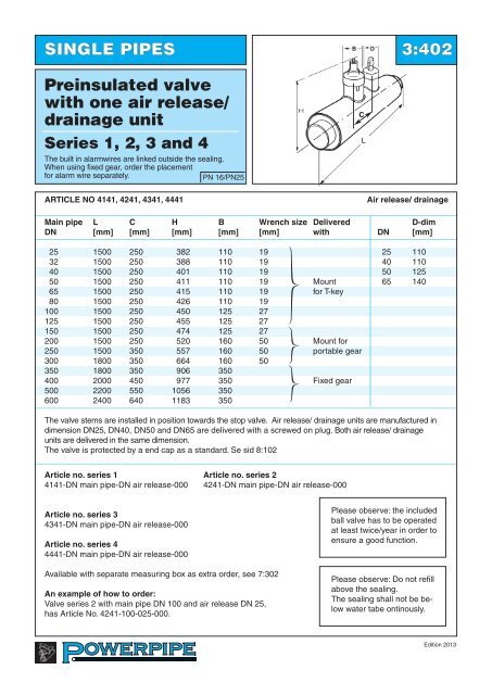
B DSINGLE PIPES 3:402Preinsulated valvewith one air release/drainage unit<strong>Series</strong> 1, 2, 3 <strong>and</strong> 4The built in alarmwires are linked outside the sealing.When using fixed gear, order the placementfor alarm wire separately.PN 16/PN25CLARTICLE NO 4141, 4241, 4341, 4441Air release/ drainageMain pipe L C H B Wrench size Delivered D-dimDN [mm] [mm] [mm] [mm] [mm] with DN [mm]25 1500 250 382 110 19 25 11032 1500 250 388 110 19 40 11040 1500 250 401 110 19 50 12550 1500 250 411 110 19 Mount 65 14065 1500 250 415 110 19 for T-key80 1500 250 426 110 19100 1500 250 450 125 27125 1500 250 455 125 27150 1500 250 474 125 27200 1500 250 520 160 50 Mount for250 1500 350 557 160 50 portable gear300 1800 350 664 160 50350 1800 350 906 350400 2000 450 977 350 Fixed gear500 2200 550 1056 350600 2400 640 1183 350The valve stems are installed in position towards the stop valve. Air release/ drainage units are manufactured indimension DN25, DN40, DN50 <strong>and</strong> DN65 are delivered with a screwed on plug. Both air release/ drainageunits are delivered in the same dimension.The valve is protected by a end cap as a st<strong>and</strong>ard. Se sid 8:102Article no. series 1 Article no. series 24141-DN main pipe-DN air release-000 4241-DN main pipe-DN air release-000Article no. series 34341-DN main pipe-DN air release-000Article no. series 44441-DN main pipe-DN air release-000Available with separate measuring box as extra order, see 7:302An example of how to order:Valve series 2 with main pipe DN 100 <strong>and</strong> air release DN 25,has Article No. 4241-100-025-000.Please observe: the includedball valve has to be operatedat least twice/year in order toensure a good function.Please observe: Do not refillabove the sealing.The sealing shall not be belowwater tabe ontinously.Edition 2013
- Page 1: INDEXGeneralinformationTechnology,q
- Page 4 and 5: Technology, Quality and Environment
- Page 6 and 7: Technology, Quality and Environment
- Page 8 and 9: Technology, Quality and Environment
- Page 10 and 11: SINGLE PIPES 3:102Straight pipesSer
- Page 12 and 13: SINGLE PIPES 3:104Straight pipesSer
- Page 14 and 15: SINGLE PIPES 3:106Curved pipesSerie
- Page 16 and 17: SINGLE PIPES 3:108Curved pipesElast
- Page 18 and 19: SINGLE PIPES 3:202Termination bend
- Page 20 and 21: L3L2SINGLE PIPES 3:302T-piece withe
- Page 22 and 23: SINGLE PIPES 3:304T-pieces withpara
- Page 26 and 27: SINGLE PIPES 3:403Valve with double
- Page 28 and 29: DesignSINGLE PIPES 3:405Valve with
- Page 30 and 31: Model BSINGLE PIPES 3:407Combinatio
- Page 32 and 33: SINGLE PIPES 3:501Anchor unitstSeri
- Page 34 and 35: SINGLE PIPES 3:503Reduction unitThe
- Page 36 and 37: DOUBLE PIPES 4:102Straight pipes,do
- Page 38 and 39: DOUBLE PIPES 4:104Straight pipes fo
- Page 40 and 41: DOUBLE PIPES 4:106Curved pipesDefle
- Page 42 and 43: DOUBLE PIPES 4:201BendHorizontalPN
- Page 44 and 45: DOUBLE PIPES 4:203Termination bend
- Page 46 and 47: DOUBLE PIPES 4:205Bend out of plane
- Page 48 and 49: DOUBLE PIPES 4:302Intersection unit
- Page 50 and 51: DOUBLE PIPES 4:304T-piece Double/si
- Page 52 and 53: DOUBLE PIPES 4:306Transition unit s
- Page 54 and 55: DOUBLE PIPES 4:402BValve unit,Compa
- Page 56 and 57: DOUBLE PIPES 4:404200Air release/ d
- Page 58 and 59: DOUBLE PIPES 4:406Combination valve
- Page 60 and 61: DOUBLE PIPES 4:408DpHValve unit wit
- Page 62 and 63: DOUBLE PIPES 4:502Anchor unittThe a
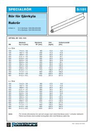
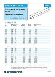
- Page 64 and 65: SPECIAL PIPES 5:101District cooling
- Page 66 and 67: SPECIAL PIPES 5:201High temperature
- Page 68 and 69: SPECIAL PIPES 5:203High temperature
- Page 70 and 71: SPECIAL PIPES 5:205High temperature
- Page 72 and 73: SPECIAL PIPES 5:302Bend with spiroa
- Page 74 and 75:
District heating for small houses 5
- Page 76 and 77:
Laying of steel- and copper pipes 5
- Page 78 and 79:
Type section for flexible pipes 5:4
- Page 80 and 81:
Flexpipe, copper 5:502Flexible pipe
- Page 82 and 83:
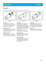
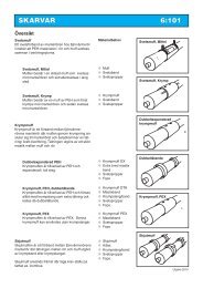
JOINTS 6:101OverviewWelding jointA
- Page 84:
JOINTS 6:103Welding joint,shrinkabl
- Page 87 and 88:
JOINTS 6:203Heat-shrinkablesleeve,P
- Page 89 and 90:
JOINTS 6:205Double sealedExtended s
- Page 91 and 92:
JOINTS 6:207Double sealedTerminatio
- Page 93 and 94:
JOINTS 6:301Tubular and openshrinki
- Page 95 and 96:
JOINTS 6:401Hot tapping T-joint wit
- Page 97 and 98:
JOINTS 6:403T-joint, 45° flexible,
- Page 99 and 100:
DyJOINTS 6:405Double sealedT-joint
- Page 101 and 102:
JOINTS 6:407Measure joint400-700Con
- Page 103 and 104:
Monitoring systems 7:1027.1 WiDetec
- Page 105 and 106:
Monitoring systems 7:104WiDetect On
- Page 107 and 108:
Monitoring systems 7:106Survey of s
- Page 109 and 110:
Monitoring systems 7:2017.2 Pipegua
- Page 111 and 112:
Monitoring systems 7:203cTubeTM Ala
- Page 113 and 114:
Monitoring systems 7:302Alarm Syste
- Page 115 and 116:
ACCESSORIES 8:101In wall sealsLEAD
- Page 117 and 118:
ACCESSORIES 8:202Shut-off valvesSER
- Page 119 and 120:
ACCESSORIES 8:302MiscellaneousHEAT
- Page 121 and 122:
ACCESSORIES 8:401Portion foamJoints
- Page 123 and 124:
Design guidelines 9:101A new pipe-S
- Page 125 and 126:
Design guidelines 9:103Assumptions
- Page 127 and 128:
Design guidelines 9:201Calculating
- Page 129 and 130:
Design guidelines 9:203Copper flexi
- Page 131 and 132:
Design guidelines 9:302Single pipe
- Page 133 and 134:
Design guidelines 9:401PlanningFoam
- Page 135 and 136:
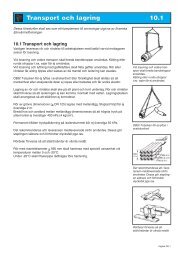
Transportation and storage 10.1Thes
- Page 137 and 138:
Trench 10.2.110.2.1 DimensionsThe p
- Page 139 and 140:
Installation 10.3.210.3.14 Angles o
- Page 141 and 142:
Installation 10.3.4Ground anchoring
- Page 143 and 144:
Installation 10.3.6Expansion absorp
- Page 145 and 146:
EksaktometerInstallation 10.3.8Insu
- Page 147 and 148:
Installation Mittel 10.3.1010.3.31
- Page 149 and 150:
Installation 10.3.1210.3.34 Double
- Page 151 and 152:
Installation 10.3.14● Check the s
- Page 153 and 154:
Installation 10.3.1610.3.35 End cap
- Page 155 and 156:
Montage 10.3.1810.3.24 Plug Instruc
- Page 157 and 158:
Installation 10.3.2010.3.39 Table f
- Page 159 and 160:
INSTALLATION 10.3.22Foam liquids fo
- Page 161 and 162:
Installation 10.3.2410.3.43 Foam li
- Page 163 and 164:
Safety rules and directions 10.5.11
- Page 165 and 166:
Instructions for ball valve 10.6.11