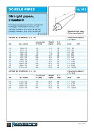
DOUBLE PIPES 4:102Straight pipes,double+<strong>Powerpipe</strong>s Double pipes are layed vertically withthe flow pipe installed below the return pipe.Article No. Double+, 12 m: 1603-DN-000-000Article No. Double+, 16 m: 1604-DN-000-000Article No. Double+, 18 m: 1605-DN-000-000PN 16/PN25Regarding heat lossesPlease see chapter 9!ARTICLE NO. DOUBLE+, 12 m, 1603Transmission capacityΔ T = 50°CService pipe Weight C-CDN Dy x s [mm] DY [mm] [kg/m] [mm] [m/s] [kW]20 26,9 x 2,0 160 6,7 19 0,8 6525 33,7 x 2,3 160 7,8 19 0,8 10032 42,4 x 2,6 180 9,9 19 0,8 18040 48,3 x 2,6 180 10,3 19 0,9 23050 60,3 x 2,9 225 14,0 20 0,9 37065 76,1 x 2,9 250 17,6 20 1,0 70080 88,9 x 3,2 280 22,8 25 1,0 1.000100 114,3 x 3,6 355 33,9 25 1,1 1.800125 139,7 x 3,6 450 46,3 30 1,3 3.300150 168,3 x 4,0 500 56,5 40 1,4 5.000ARTICLE NO. DOUBLE+, 16 m, 1604Transmission capacityΔ T = 50°CService pipe Weight C-CDN Dy x s [mm] DY [mm] [kg/m] [mm] [m/s] [kW]100 114,3 x 3,6 355 33,9 25 1,1 1.800125 139,7 x 3,6 450 46,3 30 1,3 3.300150 168,3 x 4,0 500 56,5 40 1,4 5.000ARTICLE NO. DOUBLE+, 18 m, 1605Transmission capacityΔ T = 50°CService pipe Weight C-CDN Dy x s [mm] DY [mm] [kg/m] [mm] [m/s] [kW]100 114,3 x 3,6 355 33,9 25 1,1 1.800150 168,3 x 4,0 500 56,5 40 1,4 5.000200 219,1 x 4,5 630 82,9 45 1,6 10.000Edition 2013
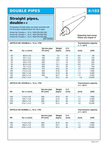
DOUBLE PIPES 4:103Straight pipes,double++<strong>Powerpipe</strong>s Double pipes are layed vertically withthe flow pipe installed below the return pipe.Article No. Double++, 12 m: 1603-DN-000-000Article No. Double++, 16 m: 1604-DN-000-000Article No. Double++, 18 m: 1605-DN-000-000PN 16/PN25Regarding heat lossesPlease see chapter 9!ARTICLE NO. DOUBLE++, 12 m, 1703Transmission capacityΔ T = 50°CService pipe Weight C-CDN Dy x s [mm] DY [mm] [kg/m] [mm] [m/s] [kW]20 26,9 x 2,0 180 7,4 19 0,8 6525 33,7 x 2,3 180 8,5 19 0,8 10032 42,4 x 2,6 200 10,6 19 0,8 18040 48,3 x 2,6 200 11,1 19 0,9 23050 60,3 x 2,9 250 15,1 20 0,9 37065 76,1 x 2,9 280 19,7 20 1,0 70080 88,9 x 3,2 315 24,9 25 1,0 1.000100 114,3 x 3,6 400 37,8 25 1,1 1.800125 139,7 x 3,6 500 51,8 30 1,3 3.300150 168,3 x 4,0 560 63,7 40 1,4 5.000200 219,1 x 4,5 710 91,2 45 1,6 10.000ARTICLE NO. DOUBLE++, 16 m, 1704Transmission capacityΔ T = 50°CService pipe Weight C-CDN Dy x s [mm] DY [mm] [kg/m] [mm] [m/s] [kW]100 114,3 x 3,6 400 37,8 25 1,1 1.800125 139,7 x 3,6 500 51,8 30 1,3 3.300150 168,3 x 4,0 560 63,7 40 1,4 5.000200 219,1 x 4,5 710 91,2 45 1,6 10.000ARTICLE NO DUBBEL++, 18 m, 1705Transmission capacityΔ T = 50°CService pipe Weight C-CDN Dy x s [mm] DY [mm] [kg/m] [mm] [m/s] [kW]100 114,3 x 3,6 400 37,8 25 1,1 1.800150 168,3 x 4,0 560 63,7 40 1,4 5.000200 219,1 x 4,5 710 91,2 45 1,6 10.000Edition 2013
- Page 1: INDEXGeneralinformationTechnology,q
- Page 4 and 5: Technology, Quality and Environment
- Page 6 and 7: Technology, Quality and Environment
- Page 8 and 9: Technology, Quality and Environment
- Page 10 and 11: SINGLE PIPES 3:102Straight pipesSer
- Page 12 and 13: SINGLE PIPES 3:104Straight pipesSer
- Page 14 and 15: SINGLE PIPES 3:106Curved pipesSerie
- Page 16 and 17: SINGLE PIPES 3:108Curved pipesElast
- Page 18 and 19: SINGLE PIPES 3:202Termination bend
- Page 20 and 21: L3L2SINGLE PIPES 3:302T-piece withe
- Page 22 and 23: SINGLE PIPES 3:304T-pieces withpara
- Page 24 and 25: SINGLE PIPES 3:401ValvesSeries 1, 2
- Page 26 and 27: SINGLE PIPES 3:403Valve with double
- Page 28 and 29: DesignSINGLE PIPES 3:405Valve with
- Page 30 and 31: Model BSINGLE PIPES 3:407Combinatio
- Page 32 and 33: SINGLE PIPES 3:501Anchor unitstSeri
- Page 34 and 35: SINGLE PIPES 3:503Reduction unitThe
- Page 38 and 39: DOUBLE PIPES 4:104Straight pipes fo
- Page 40 and 41: DOUBLE PIPES 4:106Curved pipesDefle
- Page 42 and 43: DOUBLE PIPES 4:201BendHorizontalPN
- Page 44 and 45: DOUBLE PIPES 4:203Termination bend
- Page 46 and 47: DOUBLE PIPES 4:205Bend out of plane
- Page 48 and 49: DOUBLE PIPES 4:302Intersection unit
- Page 50 and 51: DOUBLE PIPES 4:304T-piece Double/si
- Page 52 and 53: DOUBLE PIPES 4:306Transition unit s
- Page 54 and 55: DOUBLE PIPES 4:402BValve unit,Compa
- Page 56 and 57: DOUBLE PIPES 4:404200Air release/ d
- Page 58 and 59: DOUBLE PIPES 4:406Combination valve
- Page 60 and 61: DOUBLE PIPES 4:408DpHValve unit wit
- Page 62 and 63: DOUBLE PIPES 4:502Anchor unittThe a
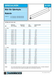
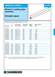
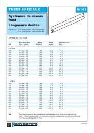
- Page 64 and 65: SPECIAL PIPES 5:101District cooling
- Page 66 and 67: SPECIAL PIPES 5:201High temperature
- Page 68 and 69: SPECIAL PIPES 5:203High temperature
- Page 70 and 71: SPECIAL PIPES 5:205High temperature
- Page 72 and 73: SPECIAL PIPES 5:302Bend with spiroa
- Page 74 and 75: District heating for small houses 5
- Page 76 and 77: Laying of steel- and copper pipes 5
- Page 78 and 79: Type section for flexible pipes 5:4
- Page 80 and 81: Flexpipe, copper 5:502Flexible pipe
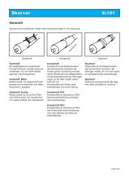
- Page 82 and 83: JOINTS 6:101OverviewWelding jointA
- Page 84: JOINTS 6:103Welding joint,shrinkabl
- Page 87 and 88:
JOINTS 6:203Heat-shrinkablesleeve,P
- Page 89 and 90:
JOINTS 6:205Double sealedExtended s
- Page 91 and 92:
JOINTS 6:207Double sealedTerminatio
- Page 93 and 94:
JOINTS 6:301Tubular and openshrinki
- Page 95 and 96:
JOINTS 6:401Hot tapping T-joint wit
- Page 97 and 98:
JOINTS 6:403T-joint, 45° flexible,
- Page 99 and 100:
DyJOINTS 6:405Double sealedT-joint
- Page 101 and 102:
JOINTS 6:407Measure joint400-700Con
- Page 103 and 104:
Monitoring systems 7:1027.1 WiDetec
- Page 105 and 106:
Monitoring systems 7:104WiDetect On
- Page 107 and 108:
Monitoring systems 7:106Survey of s
- Page 109 and 110:
Monitoring systems 7:2017.2 Pipegua
- Page 111 and 112:
Monitoring systems 7:203cTubeTM Ala
- Page 113 and 114:
Monitoring systems 7:302Alarm Syste
- Page 115 and 116:
ACCESSORIES 8:101In wall sealsLEAD
- Page 117 and 118:
ACCESSORIES 8:202Shut-off valvesSER
- Page 119 and 120:
ACCESSORIES 8:302MiscellaneousHEAT
- Page 121 and 122:
ACCESSORIES 8:401Portion foamJoints
- Page 123 and 124:
Design guidelines 9:101A new pipe-S
- Page 125 and 126:
Design guidelines 9:103Assumptions
- Page 127 and 128:
Design guidelines 9:201Calculating
- Page 129 and 130:
Design guidelines 9:203Copper flexi
- Page 131 and 132:
Design guidelines 9:302Single pipe
- Page 133 and 134:
Design guidelines 9:401PlanningFoam
- Page 135 and 136:
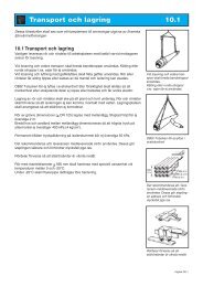
Transportation and storage 10.1Thes
- Page 137 and 138:
Trench 10.2.110.2.1 DimensionsThe p
- Page 139 and 140:
Installation 10.3.210.3.14 Angles o
- Page 141 and 142:
Installation 10.3.4Ground anchoring
- Page 143 and 144:
Installation 10.3.6Expansion absorp
- Page 145 and 146:
EksaktometerInstallation 10.3.8Insu
- Page 147 and 148:
Installation Mittel 10.3.1010.3.31
- Page 149 and 150:
Installation 10.3.1210.3.34 Double
- Page 151 and 152:
Installation 10.3.14● Check the s
- Page 153 and 154:
Installation 10.3.1610.3.35 End cap
- Page 155 and 156:
Montage 10.3.1810.3.24 Plug Instruc
- Page 157 and 158:
Installation 10.3.2010.3.39 Table f
- Page 159 and 160:
INSTALLATION 10.3.22Foam liquids fo
- Page 161 and 162:
Installation 10.3.2410.3.43 Foam li
- Page 163 and 164:
Safety rules and directions 10.5.11
- Page 165 and 166:
Instructions for ball valve 10.6.11