Operating Instructions - TEKA GmbH
Operating Instructions - TEKA GmbH
Operating Instructions - TEKA GmbH

Create successful ePaper yourself
Turn your PDF publications into a flip-book with our unique Google optimized e-Paper software.
<strong>Operating</strong> <strong>Instructions</strong><br />
Type<br />
<strong>TEKA</strong> – STRONGMASTER-BGIA<br />
<strong>TEKA</strong> Absaug- und Entsorgungstechnologie<br />
<strong>GmbH</strong><br />
Industriestraße 13 D-46342 Velen<br />
Postfach 1137 D-46334 Velen<br />
Tel.: +49 (0) 2863 9282-0<br />
Fax: +49 (0) 2863 9282-72<br />
E-Mail: sales@tekanet.de<br />
www.tekanet.de
Table of contents<br />
1 Drawing / Description of components .................................................................................................... 3<br />
2 Introduction........................................................................................................................................... 4<br />
3 Functional principle <strong>TEKA</strong> – STRONGMASTER-BGIA........................................................................ 5<br />
4 Safety instructions................................................................................................................................. 5<br />
5 Initial operations.................................................................................................................................... 7<br />
5.1 Mounting of suction arm .................................................................................................................... 7<br />
5.2 Electrical connection.......................................................................................................................... 8<br />
6 Explanation of the controls.................................................................................................................... 8<br />
7 Maintenance and service ...................................................................................................................... 9<br />
7.1 Cleaning of filter cartridge.................................................................................................................. 9<br />
7.2 Compressed air supply .................................................................................................................... 10<br />
7.3 Emptying of dust collector bin.......................................................................................................... 10<br />
7.4 Change of filter cartridge ................................................................................................................. 11<br />
8 Handling of waste................................................................................................................................ 11<br />
9 Technical data .................................................................................................................................... 12<br />
10 List of spare parts............................................................................................................................ 13<br />
11 Declaration of conformity <strong>TEKA</strong>-STRONGMASTER-BGIA ............................................................. 14<br />
BA_Strongmaster-BGIA_091218_GB.DOC - 2 - 2009-12-18
1 Drawing / Description of components<br />
Pos.1<br />
Pos.2<br />
Pos.3<br />
Pos.4<br />
Pos.5<br />
Pos.6<br />
Pos.7<br />
Pos.8<br />
Pos.9<br />
Pos.10<br />
Pos.11<br />
Pos.12<br />
Pos.13<br />
Pos.14<br />
Pos.15<br />
Pos.16<br />
Power switch<br />
<strong>Operating</strong> hour counter<br />
<strong>Operating</strong> status lamp: green<br />
Volume flow control lamp: red<br />
Signal horn<br />
Suction arm with suction hood or<br />
connecting piece<br />
Lid<br />
Hand grip<br />
Cartridge box<br />
Cartridge access door<br />
Filter cartridge<br />
Cartridge guide<br />
Cartridge bracket<br />
Fastening screw for filter cartridge<br />
Drawer box<br />
Drawer access door<br />
Pos.17<br />
Pos.18<br />
Pos.19<br />
Pos.20<br />
Pos.21<br />
Pos.22<br />
Pos.23<br />
Pos.24<br />
Pos.25<br />
Pos.26<br />
Pos.27<br />
Pos.28<br />
Pos.29<br />
Pos.30<br />
Pos.31<br />
Pos.32<br />
Dust collecting bin<br />
Lifting device<br />
Fastening screw for dust collecting bin<br />
Fan housing<br />
Fan access door<br />
Cleaning access door<br />
Over-centre lock<br />
Cap nut for cartridge door<br />
Caster with brake<br />
Caster<br />
Screw for mounting of suction arm<br />
Spring washer for mounting of suction arm<br />
Turning flange<br />
Cap nut for fan access door<br />
Mains cable with plug and indicator for<br />
sense of rotation: red<br />
Dust collecting bag<br />
BA_Strongmaster-BGIA_091218_GB.DOC - 3 - 2009-12-18
2 Introduction<br />
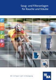
In recent years, a special type of welding fume extraction systems has become an ever more<br />
prominent factor: Filtering of welding fumes and return of the filtered air into the workshop area.<br />
This shows that the issue of environmental consideration has turned for the better for all concerned.<br />
There never has been any doubt about the existence of harmful fumes at welding sites. However, type<br />
of fumes depends on the particular welding process and welding technique. One can generally<br />
differentiate between gases and fumes. The fumes could also be referred to as fine dust. Investigating<br />
them under the microscope, we are able to see particles of a size that will pass through the respiratory<br />
tract deep into our lungs. The size of these particles is a small as 0.001 mm or even less.<br />
Ventilation is the general approach to improve the conditions at the relevant work positions. Generally,<br />
this is effected by continuously exchanging the air in the workshop, i.e. the total air volume is<br />
exchanged at a high rate. This method will reduce the concentration of harmful particles within the hall<br />
to a great extent, however, it will improve the air within the breathing range of the individual welder to a<br />
negligible portion only.<br />
This also applies to overhead suction systems, i.e. the installation of large extraction hoods overhead<br />
of welding places. Here again the heavily polluted air passes upwards through the breathing range of<br />
the welder. Extraction and/or filtering take place overhead and outside the range of the welder. A pointattack<br />
extraction of the welding fumes right at their place of origin is far more effective than room<br />
ventilation or overhead extraction. Both capital investment for on-the-spot fume extraction as well as<br />
the operating costs for such systems are far below those of the previous conventional solutions.<br />
Environmental and work protection measures are prerequisite for the successful application of<br />
advanced welding technologies, aside from the optimisation of such welding processes. In view of<br />
increased awareness of the problems involved and in compliance with pertinent legal directives, the<br />
danger potential for personnel and environment must be considered at an early stage and it must be<br />
minimised using appropriate technical solutions.<br />
BA_Strongmaster-BGIA_091218_GB.DOC - 4 - 2009-12-18
3 Functional principle <strong>TEKA</strong> – STRONGMASTER-BGIA<br />
The filter unit <strong>TEKA</strong> - STRONGMASTER-BGIA is used mainly for extracting welding fumes on the<br />
spot. One or two flexible extraction hoses or other specific conduits are provided for the specific type of<br />
application.<br />
Operational limits:<br />
welding fumes containing oil mist, aluminium dust, grinding dust, suction of metallic dusts, gases,<br />
water, etc. (If there is any doubt about the application, please contact the manufacturer.)<br />
The polluted air is extracted via the suction hood (or a specific suction head) and directed into the<br />
suction arm (or suction hose) and into the filter unit. Here, the particles are collected on the surface of<br />
the filter cartridge. The clean air passes the fan and returns into the room via the exhaust grid Pos.31).<br />
Caution:<br />
As soon as the accumulated dust particles on the filter cartridge yield a maximum resistance to the air<br />
flow, the integrated electronic control will illuminate the red lamp of the air flow volume control (Pos.4)<br />
and the signal horn Pos.5) will sound.<br />
The filter cake is removed by manually by directing the air jet of a compressed air pistol onto the filter<br />
area.<br />
(Refer to chapter 6.1 ‘Cleaning of filter cartridge)<br />
The removed filter cake is gathered in the dust collecting bin from which it can be taken for final waste<br />
handling.<br />
(Refer to chapter 6.3 ‘Emptying of the dust collector bin’)<br />
4 Safety instructions<br />
The following basic safety measures must be observed to prevent of electric shocks, injury or fire when<br />
using electrical devices:<br />
• Read and follow the instructions listed below before using the filter systems !<br />
• Store the operating and service instructions in a secure and readily accessible space !<br />
• Do not employ the unit for the extraction of easily combustible or explosive gases!<br />
• Do not employ the unit for the extraction of aggressive media !<br />
• Do not employ the unit for setting it in explosive zones, e.g. zone 0, zone 1, zone 2, zone 20,<br />
zone 21, zone 22!<br />
• Do not employ the unit for sucking off burning or glowing materials, e.g. cigarettes, matches,<br />
metallic types of dust and/or splinters, paper, cleaning cloths, etc.!<br />
• Do not employ the unit for sucking off burning and/or inflammatory materials, e.g. oils and/or<br />
oil mist, fats, parting agent (e.g. silicone spray), cleaning agent, etc.!<br />
BA_Strongmaster-BGIA_091218_GB.DOC - 5 - 2009-12-18
• Do not employ the unit for the sucking up of liquids of any kind !<br />
• Do not employ the unit for extraction of any organic matters without the written permission<br />
of the manufacturer !<br />
• Protect the connecting lead from heat, wetness, oils and sharp edges !<br />
Confirm the correct voltage. (Refer to the unit type plate)<br />
• Use only original <strong>TEKA</strong> spare parts !<br />
• Do not operate the unit without a filter cartridge installed !<br />
• Pull the mains plug before opening the unit !<br />
• The exhaust gird must not be obstructed or blocked in any way!<br />
• Always take care that the unit stands secured and that the caster brakes are set !<br />
• Pull the mains plug when cleaning or servicing the unit, when exchanging any parts or when<br />
changing machine settings for a different function !<br />
• The filter cartridges cannot be regenerated for repeated use !<br />
• The filter cartridges must be disposed of according to pertinent legislation and directives !<br />
• At regular intervals inspect the mains supply lead for signs of damage !<br />
• The unit must not be used when there is any damage or irregularity at the mains supply lead !<br />
• Use only dry and oil-free compressed air with pressure ratings from minimum 3 bar to 4 bar<br />
maximum.<br />
• Reposition the suction arm during welding operations, if possible by exploiting the thermal flow<br />
of the welding fumes<br />
• The maximum permissible distance of 25 cm to the welding point should not be exceeded.<br />
• Do not use the filter unit when any one or more components of the system are defective,<br />
missing or damaged. In any one of these instances contact the <strong>TEKA</strong> Service<br />
Department: Phone: ++49 (0) 2863 / 92 82 0<br />
• When extracting carcinogenic welding fumes as from the processing of nickel or chrome alloys,<br />
the requirements of the directives on clean air of the German TRGS 560 ‘Return of process air<br />
when working with carcinogenic media’must be observed. (And/or the equivalent<br />
national directives for the respective user.) The suction unit <strong>TEKA</strong>-STRONGMASTER-<br />
BGIA2110/4110 has been checked and approved by the Institute for Work Safety (BGIA) under<br />
the certification number xxxxxx. This certification is part of the operating instructions.<br />
• Further information regarding the TRGS 560 can be obtained from the<br />
‘BGIA - Berufsgenossenschaftliches Institut für Arbeitssicherheit’<br />
(Institute for work safety of the employers’liability insurances) at<br />
D-53754 Sankt Augustin, Germany.<br />
BA_Strongmaster-BGIA_091218_GB.DOC - 6 - 2009-12-18
5 Initial operations<br />
The filter unit is delivered in a state ready to be plugged to the mains supply.<br />
Prior do using the machine, the extraction/suction elements, e.g. the suction arm and appropriate<br />
optional accessories, must be mounted or installed.<br />
5.1 Mounting of suction arm<br />
Attach the suction element (Pos.6) e.g. the suction arm or the connecting piece and clamping flange<br />
(Pos.29), screws (Pos.27) and spring washers (Pos.28).<br />
Caution:<br />
The connecting element must move/turn freely !<br />
BA_Strongmaster-BGIA_091218_GB.DOC - 7 - 2009-12-18
5.2 Electrical connection<br />
• Connect the filter unit to the mains supply. (Observe the information on the type plate!)<br />
• If the red control lamp at the connector for the sense of rotation (Pos.31) illuminates,<br />
immediately disconnect the unit from the mains supply (pull the plug) and thereafter change the<br />
terminal position of two phases at the socket in order to change the electrical field of the rotary<br />
current.<br />
(If the unit operates on 230 V single phase current, there is no need to check the electrical<br />
field.)<br />
• Connect the filter unit to the mains supply. (Observe the information on the type plate!)<br />
Caution:<br />
Work at the electrical components may be executed by authorised personnel only!<br />
Observe the information on the type plate!<br />
6 Explanation of the controls<br />
Pos.1<br />
Pos.2<br />
Pos.3<br />
The main switch switches the filter unit on or off.<br />
The operating hour counter starts to count as soon as the filter unit will be switch on.<br />
The operating status lamp shows if the filter unit will be switch on.<br />
Pos.4 The indicator lamp for flow volume shows whether the suction power is adequate. If it lights<br />
up, the filter inserts must be replaced.<br />
Pos.5 The signal horn shows whether the suction power is adequate. When releasing acoustic<br />
signal, the filter inserts must be replaced.<br />
BA_Strongmaster-BGIA_091218_GB.DOC - 8 - 2009-12-18
7 Maintenance and service<br />
The accumulation of extracted particles on the filter cartridge will eventually lead to a reduction of the<br />
suction / extraction performance.<br />
The rate of accumulation and thereby the degrading of the filter cartridge (Pos.11) is monitored<br />
electronically. In order to maintain the designed suction performance, the filter cartridge must be<br />
cleaned when the red volume control lamp (Pos.4) illuminates and/or the signal horn (Pos.5) sounds.<br />
(Refer to chapter 6.1: ”Cleaning of filter cartridge / Manual cleaning”)<br />
The accumulated dust particles are blown off the filter by applying compressed air from the clean side.<br />
The released filter cake will drop into the dust collecting bin (Pos.17). (Refer to chapter 6.3: ”Emptying<br />
of dust collector bin”)<br />
The useful service life of the filter cartridge greatly depends on the operational environment. For this<br />
reason, it cannot be predicted.<br />
If the operating pressure of the filter unit should not be achieved after cleaning the filter cartridge, the<br />
cartridge must be replaced. (Refer to chapter 6.5: ”Change of filter cartridge”)<br />
Caution:<br />
Stop the operation of the filter unit when changing the filter cartridge.<br />
Exchange of the filter cartridge and the disposal of the element may be executed only in amply<br />
ventilated environments and when using an appropriate protective respiratory mask !<br />
We recommend to use a respiratory mask to DIN EN 141/143 - Protection class P3.<br />
The task of changing the filter elements should be executed by trained personnel only !<br />
7.1 Cleaning of filter cartridge<br />
When the red volume control lamp (Pos.4) illuminates and the signal horn (Pos.5) sounds, the filter<br />
cartridge must be cleaned according to the following procedure:<br />
• Disconnect the filter unit from the mains supply (Pull the plug) !<br />
• Close the throttling flap at the suction hood.<br />
• Open the cleaning access door (Pos.22) by releasing the overcentre lock (Pos.23).<br />
• Evenly apply the air jet from the compressed air pistol (available as an option) to the filter<br />
cartridge (Pos.11). (Refer to chapter 6.2. “Compressed air supply”)<br />
• Apply the air jet for ca. ca. 5 – 10 minutes.<br />
• Close the cleaning access door (Pos.22) and secure it with the overcentre lock (Pos.23).<br />
• Connect the filter unit to the mains supply.<br />
(Observe the information on the type plate!)<br />
BA_Strongmaster-BGIA_091218_GB.DOC - 9 - 2009-12-18
Caution:<br />
Without the compressed air supply, the filter cartridge will be clogged, and its performance will degrade<br />
rapidly. The unit will indicate a fault (Filter clogged/full) !<br />
Do not manually shake or wash the filter element as this will damage the filter medium, and the harmful<br />
waste particles will be returned into the workshop's atmosphere !<br />
7.2 Compressed air supply<br />
A suitable compressed air supply must be proved to ensure the correct function of the suction unit.<br />
• The compressed air must be dry and oil-free.<br />
• External air supply via an approved pressure hose and at an operating pressure from 3 bar<br />
minimum to 4 bar maximum.<br />
Caution:<br />
Without the compressed air supply, the filter cartridge will be clogged, and its performance will degrade<br />
rapidly. The unit will indicate a fault (Filter clogged/full) !<br />
7.3 Emptying of dust collector bin<br />
After a certain number of operating hours, the duct collector bin (Pos.17) shall be cleaned. The schedule<br />
depends on the mass of accumulated dust.<br />
• Disconnect the unit from the mains supply (Pull the plug).<br />
• Open the drawer access door (Pos.16).<br />
• Lower the lifting device (Pos.18) by turning the fastening screw (Pos.19) downward.<br />
• Pull out the dust collector bin (Pos.17).<br />
• The dust collecting bag (Pos.32) with the accumulated dust take and lock.<br />
• The accumulated dust must be store/dispose off the matter according to pertinent directives.<br />
• A new plastic bag into the dust collecting bag insert, so that the opening of the bag is inverted<br />
over the edge of the Staubsammellade<br />
• Push the dust collector bin (Pos.17) all the way back into the drawer box (Pos.15).<br />
• Raise the lifting device (Pos.18) by turning the fastening screw (Pos.19) until the dust collector<br />
bin (Pos.17) sits tight and leak-free.<br />
(Also check for possible damage of the sealing gasket under the cartridge box (Pos.9).)<br />
• Close the drawer access door (Pos.16).<br />
• Connect the filter unit to the mains supply.<br />
(Observe the information on the type plate!)<br />
BA_Strongmaster-BGIA_091218_GB.DOC - 10 - 2009-12-18
Caution:<br />
Exchange of the filter cartridge and the disposal of the element may be executed only in amply<br />
ventilated environments and when using an appropriate protective respiratory mask !<br />
We recommend to use a respiratory mask to DIN EN 141/143 - Protection class P3.<br />
The task of changing the filter elements should be executed by trained personnel only !<br />
7.4 Change of filter cartridge<br />
• Disconnect the filter unit from the mains supply.<br />
• Release the cap nut (Pos.24) and open the cartridge access door (Pos.10).<br />
• Release the fastening screw (Pos.14) of the cartridge bracket (Pos.13).<br />
• Pull out the filter cartridge (Pos.11).<br />
• Push the new filter cartridge into the cartridge guide (Pos.12).<br />
Caution:<br />
Only use original <strong>TEKA</strong> replacement filter cartridges !<br />
• Tighten the fastening screw (Pos.14) of the cartridge bracket (Pos.13).<br />
• Close the cartridge access door (Pos.10) and tighten the cap nut (Pos.24).<br />
• Connect the filter unit to the mains supply.<br />
(Observe the information on the type plate!)<br />
Caution:<br />
Exchange of the filter cartridge and the disposal of the element may be executed only in amply<br />
ventilated environments and when using an appropriate protective respiratory mask !<br />
We recommend to use a respiratory mask to DIN EN 141/143 - Protection class P3.<br />
The task of changing the filter elements should be executed by trained personnel only !<br />
Disposal of the old filter cartridge according to pertinent directives !<br />
8 Handling of waste<br />
To ensure an efficient and orderly operation of your <strong>TEKA</strong>-STRONGMASTER-BGIA extraction unit and<br />
for compliance with the correct disposal of the collected dust media, we offer the following services:<br />
• A list of such speciality companies in Germany can be provided on your request at no extra cost.<br />
• Our customer services by phone or Fax<br />
Feel free to contact our Service Department where you will be assisted on a round-the-clock basis:<br />
Phone: ++49 (0) 2863 / 9282-0 Fax: ++49 (0)2863 / 9282-72<br />
BA_Strongmaster-BGIA_091218_GB.DOC - 11 - 2009-12-18
9 Technical data<br />
Caution:<br />
Refer to the data on the type plate !<br />
Filter unit<br />
<strong>TEKA</strong> - STRONGMASTER-BGIA<br />
Electrical power supply V 230 400 500<br />
Current Ph 1 3 3<br />
Frequency Hz 50<br />
Motor rating kW 1,1<br />
Air volume flow, max. m³/h 2200<br />
Vacuum, max. Pa 2500<br />
Protection class IP 54<br />
ISO - class<br />
F<br />
Control voltage V 24<br />
<strong>Operating</strong> time % 100<br />
Width x Depth x Height mm 665 x 896 x 1234<br />
Weight kg 130<br />
Number of suction arms 1<br />
Typy of filter<br />
Filter cartridge<br />
Filter area of filter cartridge m² 10<br />
Rate of extraction/separation % >99<br />
Mode of cleaning<br />
Noise level<br />
(Measured acc. to DIN 45635 T1 in 1m distance<br />
from the surface of the unit in a clear area at the<br />
maximum air flow volume.)<br />
Compressed air<br />
manual<br />
dB(A) 72<br />
External<br />
Pressure, min. bar 3<br />
Pressure, max. bar 4<br />
Compressed air supply<br />
dry / oil-free<br />
BA_Strongmaster-BGIA_091218_GB.DOC - 12 - 2009-12-18
10 List of spare parts<br />
Designation:<br />
Article-No.:<br />
Motor 1.1 kW 230V 1Ph 50 Hz 66664<br />
Motor 1.1 kW 400V 3 Ph 50 Hz 951009<br />
Power switch On / Off (Pos.1) 96354<br />
<strong>Operating</strong> hour counter (Pos.2) 96350<br />
<strong>Operating</strong> status lamp (Pos.3) 96352<br />
Volume flow control lamp (rot) (Pos.4) 96351<br />
Signal horn (Pos.5) 10317<br />
Hand grip (Pos.9) 10505<br />
Cartridge access door (Pos.10) 10503<br />
Drawer access door (Pos.16) 66660<br />
Fan access door (Pos.21) 66619<br />
Cleaning access door (Pos.22) 66661<br />
Caster with brake (Pos.25) 10022<br />
Caster (Pos.26) 10025<br />
Spare hose, suction arm 2 m 101925<br />
Spare hose, suction arm 3 m 101926<br />
Spare hose, suction arm 4 m 101927<br />
Suction hood 66200<br />
Hose clamp 10228<br />
Compressed air pistol 99005<br />
BA_Strongmaster-BGIA_091218_GB.DOC - 13 - 2009-12-18
11 Declaration of conformity <strong>TEKA</strong>-STRONGMASTER-BGIA<br />
<strong>TEKA</strong> Absaug - und Entsorgungstechnologie <strong>GmbH</strong><br />
Industriestraße 13<br />
D - 46342 Velen<br />
Phone.:+49 2863 92820 Fax:+49 2863 928272<br />
e-Mail: sales@tekanet.de Internet: http://www.tekanet.de<br />
We herewith declare in sole responsibility that the before mentioned product, starting from machine No.:<br />
110000000, conforms to the following standards:<br />
Directives on machine building:<br />
Electromagnetic compatibility:<br />
Directives on printing device:<br />
Directives on low voltage:<br />
Applied harmonised standards:<br />
- DIN EN 349<br />
- DIN EN 983<br />
- DIN EN 12100 part 1 and part 2<br />
- DIN EN 60204 part 1<br />
- DIN EN ISO 13857<br />
- DIN EN ISO 14121<br />
2006/42/EG<br />
2004/108/EG<br />
97/23/EG<br />
2006/95/EG<br />
plus further national standards and specifications:<br />
- DIN 45635 Teil 1<br />
This declaration will become void if changes are effected to the suction and filter systems which were not<br />
agreed upon in writing by the manufacturer.<br />
Velen, the 18.December 2009<br />
<strong>TEKA</strong><br />
Absaug - und Entsorgungstechnologie <strong>GmbH</strong><br />
(Extraction and Waste Handling Technology)<br />
BA_Strongmaster-BGIA_091218_GB.DOC - 14 - 2009-12-18