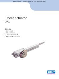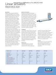
Linear actuators
Linear actuators
Linear actuators

Create successful ePaper yourself
Turn your PDF publications into a flip-book with our unique Google optimized e-Paper software.
<strong>Linear</strong> <strong>actuators</strong><br />
MAGFORCE STG<br />
www.lmotion.ru skf@lmotion.ru Тел. (495)-921-34-60<br />
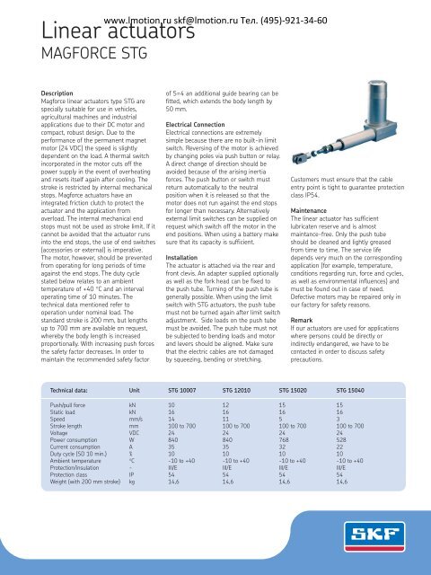
Description<br />
Magforce linear <strong>actuators</strong> type STG are<br />
specially suitable for use in vehicles,<br />
agricultural machines and industrial<br />
applications due to their DC motor and<br />
compact, robust design. Due to the<br />
performance of the permanent magnet<br />
motor (24 VDC) the speed is slightly<br />
dependent on the load. A thermal switch<br />
incorporated in the motor cuts off the<br />
power supply in the event of overheating<br />
and resets itself again after cooling. The<br />
stroke is restricted by internal mechanical<br />
stops. Magforce <strong>actuators</strong> have an<br />
integrated friction clutch to protect the<br />
actuator and the application from<br />
overload. The internal mechanical end<br />
stops must not be used as stroke limit. If it<br />
cannot be avoided that the actuator runs<br />
into the end stops, the use of end switches<br />
(accessories or external) is imperative.<br />
The motor, however, should be prevented<br />
from operating for long periods of time<br />
against the end stops. The duty cycle<br />
stated below relates to an ambient<br />
temperature of +40 °C and an interval<br />
operating time of 10 minutes. The<br />
technical data mentioned refer to<br />
operation under nominal load. The<br />
standard stroke is 200 mm, but lengths<br />
up to 700 mm are available on request,<br />
whereby the body length is increased<br />
proportionally. With increasing push forces<br />
the safety factor decreases. In order to<br />
maintain the recommended safety factor<br />
of S=4 an additional guide bearing can be<br />
fitted, which extends the body length by<br />
50 mm.<br />
Electrical Connection<br />
Electrical connections are extremely<br />
simple because there are no built-in limit<br />
switch. Reversing of the motor is achieved<br />
by changing poles via push button or relay.<br />
A direct change of direction should be<br />
avoided because of the arising inertia<br />
forces. The push button or switch must<br />
return automatically to the neutral<br />
position when it is released so that the<br />
motor does not run against the end stops<br />
for longer than necessary. Alternatively<br />
external limit switches can be supplied on<br />
request which switch off the motor in the<br />
end positions. When using a battery make<br />
sure that its capacity is sufficient.<br />
Installation<br />
The actuator is attached via the rear and<br />
front clevis. An adapter supplied optionally<br />
as well as the fork head can be fixed to<br />
the push tube. Turning of the push tube is<br />
generally possible. When using the limit<br />
switch with STG <strong>actuators</strong>, the push tube<br />
must not be turned again after limit switch<br />
adjustment. Side loads on the push tube<br />
must be avoided. The push tube must not<br />
be subjected to bending loads and motor<br />
and levers should be aligned. Make sure<br />
that the electric cables are not damaged<br />
by squeezing, bending or stretching.<br />
Customers must ensure that the cable<br />
entry point is tight to guarantee protection<br />
class IP54.<br />
Maintenance<br />
The linear actuator has sufficient<br />
lubricaten reserve and is almost<br />
maintance-free. Only the push tube<br />
should be cleaned and lightly greased<br />
from time to time. The service life<br />
depends very much on the corresponding<br />
application (for example, temperature,<br />
conditions regarding run, force and cycles,<br />
as well as environmental influences) and<br />
must be found out in case of need.<br />
Defective motors may be repaired only in<br />
our factory for safety reasons.<br />
Remark<br />
If our <strong>actuators</strong> are used for applications<br />
where persons could be directly or<br />
indirectly endangered, we have to be<br />
contacted in order to discuss safety<br />
precautions.<br />
Technical data: Unit STG 10007 STG 12010 STG 15020 STG 15040<br />
Push/pull force kN 10 12 15 15<br />
Static load kN 16 16 16 16<br />
Speed mm/s 14 11 5 3<br />
Stroke length mm 100 to 700 100 to 700 100 to 700 100 to 700<br />
Voltage VDC 24 24 24 24<br />
Power consumption W 840 840 768 528<br />
Current consumption A 35 35 32 22<br />
Duty cycle (SD 10 min.) % 10 10 10 10<br />
Ambient temperature °C -10 to +40 -10 to +40 -10 to +40 -10 to +40<br />
Protection/insulation - III/E III/E III/E III/E<br />
Protection class IP 54 54 54 54<br />
Weight (with 200 mm stroke) kg 14,6 14,6 14,6 14,6
www.lmotion.ru skf@lmotion.ru Тел. (495)-921-34-60<br />
<strong>Linear</strong> <strong>actuators</strong> MAGFORCE STG<br />
Accessories<br />
– adapter 1031,0106<br />
– fork head complete 1051,9038<br />
– limit switches complete<br />
0 ... 370 mm stroke lengths<br />
1043,0268<br />
– limit switches complete<br />
100 ... 445 mm stroke lengths<br />
1043,0252<br />
– limit switches complete<br />
200 ... 740 mm stroke lengths<br />
1043,0266<br />
– potentiometer 475 mm stroke lengths<br />
1 kΩ standard 1063,0011<br />
– potentiometer max. 944 mm<br />
stroke lengths<br />
1 kΩ standard 1063,0012<br />
– other potentiometer values on request<br />
– extended motor shaft<br />
– magnetic brake<br />
– back-up nut<br />
M 18 x 2,5<br />
Adapter<br />
24 VDC +<br />
-<br />
Stroke<br />
40 SW 30<br />
17<br />
82<br />
Stroke + 290<br />
25<br />
K1<br />
K2<br />
Brown<br />
1,5<br />
x<br />
32<br />
M<br />
Blue<br />
†40<br />
3 6<br />
9 18 9<br />
Fork head<br />
800<br />
S = 4<br />
700<br />
600<br />
500<br />
400<br />
300<br />
22 36<br />
18<br />
Stroke<br />
Stroke + 377<br />
Stroke + 419<br />
SW 27<br />
SW 30<br />
Add. bearing<br />
recommended<br />
F<br />
Wiring diagram<br />
Stroke mm<br />
200<br />
100<br />
standard<br />
guiding<br />
0<br />
0 2 4 6 8 10 12 14 16 kN<br />
Load<br />
Diagram bending of spindle<br />
S = safety factor Euler 3<br />
†113<br />
61<br />
†113<br />
Side view<br />
35<br />
†140<br />
1,5<br />
x<br />
M32<br />
Cable 500 mm<br />
Limit switches or<br />
potentiometer on request<br />
20<br />
† 4 0<br />
Stroke<br />
173<br />
Fixing length = Stroke + 273<br />
Stroke + 293<br />
†16<br />
67<br />
N75<br />
69<br />
20<br />
† 6 5<br />
95<br />
Rear view<br />
95 67<br />
Top view<br />
31<br />
25 20<br />
115<br />
Magnetic Elektromotoren AG<br />
CH-4410 Liestal, Switzerland<br />
Tel +41 61 925 4111, Fax +41 61 921 3704<br />
E-mail magnetic.switzerland@skf.com<br />
Publication L5321,2330EN.0/07.02<br />
® SKF and Magnetic are registered trademarks of the SKF Group.<br />
© SKF Group 2007.<br />
The contents of this publication are the copyright of the publisher and may not be reproduced<br />
(even extracts) unless prior written permission is granted. Every care has been taken to ensure<br />
the accuracy of the information contained in this publication but no liability can be accepted for<br />
any loss or damage whether direct, indirect or consequential arising out of the use of the<br />
information contained herein.