Precision rail guides
Precision rail guides
Precision rail guides

You also want an ePaper? Increase the reach of your titles
YUMPU automatically turns print PDFs into web optimized ePapers that Google loves.
www.lmotion.ru skf@lmotion.ru Тел. (495)-921-34-60<br />
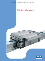
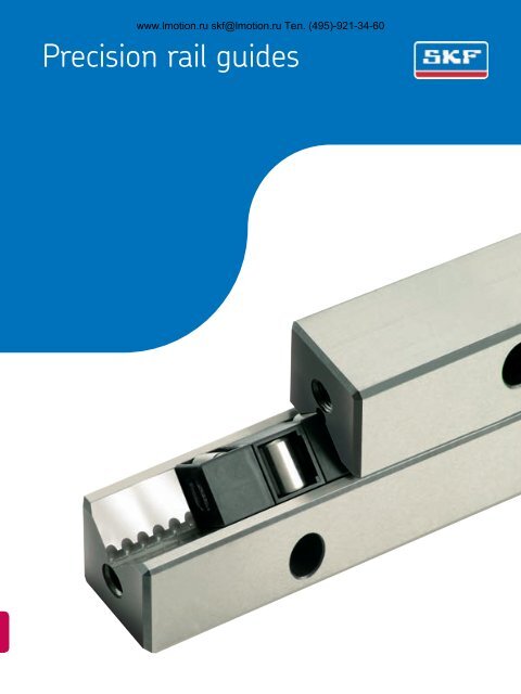
<strong>Precision</strong> <strong>rail</strong> <strong>guides</strong>
www.lmotion.ru skf@lmotion.ru Тел. (495)-921-34-60<br />
Content<br />
General information<br />
3 Introduction<br />
4 Produkt overview<br />
4 Modular Range <strong>rail</strong> <strong>guides</strong><br />
8 Other products<br />
The SKF ® brand now stands for more<br />
than ever before, and means more to<br />
you as a valued customer.<br />
While SKF maintains its leadership<br />
as the hallmark of quality bearings<br />
throughout the world, new dimensions<br />
in technical advances, product support<br />
and services have evolved SKF into<br />
a truly solutions-oriented supplier,<br />
creating greater value for customers.<br />
These solutions encompass ways to<br />
bring greater productivity to customers,<br />
not only with breakthrough applicationspecific<br />
products, but also through<br />
leading-edge design simulation tools<br />
and consultancy services, plant asset<br />
efficiency maintenance programmes,<br />
and the industry’s most advanced<br />
supply management techniques.<br />
The SKF brand still stands for the very<br />
best in rolling bearings, but it now<br />
stands for much more.<br />
SKF – the knowledge engineering<br />
company<br />
Technical data<br />
9 <strong>Precision</strong> of <strong>rail</strong> <strong>guides</strong><br />
9 Raceway accuracy<br />
9 Dimensional accuracy<br />
10 Grading<br />
10 Tolerance of distance between attachment holes<br />
10 Marking of matches sets<br />
11 Accuracy of adjacent components<br />
11 Selection of <strong>rail</strong> <strong>guides</strong><br />
SKF precision <strong>rail</strong> <strong>guides</strong> in kit packaging<br />
12 Rail <strong>guides</strong> in kit packaging<br />
12 Advantages of <strong>rail</strong> guide kits<br />
12 LWR <strong>rail</strong> <strong>guides</strong> in kit packaging - table<br />
13 LWRE <strong>rail</strong> <strong>guides</strong> in kit packaging - table<br />
13 LWRE ACS <strong>rail</strong> <strong>guides</strong> in kit packaging (supplied to order) - table<br />
LWR <strong>rail</strong> <strong>guides</strong><br />
14 LWR <strong>rail</strong> <strong>guides</strong> with crossed roller assemblies<br />
14 LWR <strong>rail</strong> <strong>guides</strong> with ball assembly<br />
15 Ball and crosses roller assemblies<br />
18 Accessories for LWR <strong>rail</strong> <strong>guides</strong><br />
LWRE <strong>rail</strong> <strong>guides</strong><br />
20 LWRE <strong>rail</strong> <strong>guides</strong><br />
21 Crossed roller assemblies<br />
21 Special attachment screws<br />
22 LWRE 3 - LWRE 9 / LWRE 2211<br />
24 Accessories for LWRE <strong>rail</strong> <strong>guides</strong><br />
25 LWRE ACS <strong>rail</strong> <strong>guides</strong> with non-slip cage (Anti Creep System)<br />
26 Accessories for LWRE ACS <strong>rail</strong> <strong>guides</strong><br />
LWRM/LWRV <strong>rail</strong> <strong>guides</strong><br />
29 LWRM/LWRPV <strong>rail</strong> <strong>guides</strong><br />
30 LWRM/LWRV 6 and LWRM/LWRV 9<br />
32 Accessories for LWRPM/LWRPV <strong>rail</strong> <strong>guides</strong><br />
LWRPM/LWRPV <strong>rail</strong> <strong>guides</strong><br />
33 LWM/LWV <strong>rail</strong> <strong>guides</strong><br />
34 LWRPM/LWRPV 3 - LWRPM/LWRPV 9<br />
36 Accessories for LWRPM/LWRPV <strong>rail</strong> <strong>guides</strong><br />
LWM/LWV <strong>rail</strong> <strong>guides</strong><br />
37 LWRPM/LWRPV <strong>rail</strong> <strong>guides</strong><br />
38 LWM/LWV 3015 - LWM/LWV 8050<br />
40 Accessories for LWM/LWV <strong>rail</strong> <strong>guides</strong><br />
LWJ/LWS flat <strong>rail</strong> <strong>guides</strong><br />
41 LWJ/LWS flat <strong>rail</strong> <strong>guides</strong><br />
LZM miniature slide<br />
42 LZM miniature slide<br />
Standard slides<br />
44 Design and characteristic features<br />
45 Technical data<br />
46 GCL - Drill hole pattern in top plate<br />
47 GCL - Drill hole pattern in base plate<br />
2
www.lmotion.ru skf@lmotion.ru Тел. (495)-921-34-60<br />
Introduction<br />
As the world’s leading rolling bearing<br />
manufacturer, SKF supplies practically<br />
every type of bearing for rotational<br />
and linear motion.<br />
SKF is therefore in a position to<br />
meet almost any customer requirement<br />
both technically and economically.<br />
This catalogue covers the SKF<br />
range of precision <strong>rail</strong> <strong>guides</strong> and accessories.<br />
SKF precision <strong>rail</strong> <strong>guides</strong> are<br />
highly accurate products for linear<br />
motion and are therefore ideally<br />
suited for use in a wide variety of<br />
machine tools, machining centres,<br />
handling systems and special machinery<br />
as well as measuring and testing<br />
equipment.<br />
The “Modular Range” has introduced<br />
a new concept to the market,<br />
ensuring the internal interchangeability<br />
of all well-known guidance systems<br />
including the high capacity<br />
LWRE-type <strong>rail</strong> <strong>guides</strong>. This matrix<br />
range of <strong>rail</strong> guide modules permits<br />
the individual selection of <strong>rail</strong>s and<br />
rolling elements.<br />
SKF precision <strong>rail</strong> <strong>guides</strong> are available<br />
in many different designs, sizes<br />
and standard lengths, incorporating<br />
ball, roller or needle roller assemblies<br />
and slide coating. They are supplied<br />
with the required accessories for attachment<br />
and sealing.<br />
The use of SKF precision <strong>rail</strong> <strong>guides</strong><br />
facilitates the construction of<br />
economical, clearance-free linear<br />
<strong>guides</strong> of practically any type and<br />
length, according to the building<br />
block principle. The characteristics of<br />
the <strong>guides</strong> include:<br />
• a constant, high degree of running<br />
accuracy<br />
• low-friction, stick-slip free operation<br />
• high speed of travel<br />
• low heat generation<br />
• low wear and high reliability<br />
• high stiffness<br />
• excellent load carrying capacity<br />
If there is a danger of cage-creep<br />
(in particular when the guide is<br />
mounted vertically), precision <strong>rail</strong><br />
<strong>guides</strong> of type LWRE-ACS (Anti-<br />
Creep System) are an obvious choice,<br />
as they will eliminate this problem.<br />
For applications that are characterised<br />
by high accelerations or short<br />
strokes of high frequency, SKF <strong>rail</strong><br />
<strong>guides</strong> with dry sliding coating are<br />
recommended.<br />
These <strong>rail</strong> <strong>guides</strong> are also suitable<br />
for machine tool applications where<br />
the good damping properties of the<br />
<strong>guides</strong> are of greater importance<br />
than the lower friction of the rolling<br />
element <strong>rail</strong> <strong>guides</strong>. For those applications<br />
where <strong>rail</strong> <strong>guides</strong> are unsuitable,<br />
for instance because of their<br />
limited travel, SKF can supply alternative<br />
forms of linear guidance systems.<br />
All fast-selling precision <strong>rail</strong> <strong>guides</strong><br />
are also available in convenient<br />
kit packaging. This ensures complete<br />
delivery of all single components including<br />
end pieces and screws.<br />
If you would like further details,<br />
please contact the SKF application<br />
engineering department. We will be<br />
pleased to provide the required information<br />
without obligation and at<br />
no cost, or to prepare a technical<br />
proposal.<br />
This catalogue brings together all<br />
the basic data which we consider to<br />
be of interest. For further specialised<br />
advice please contact your nearest<br />
SKF sales office.<br />
3
www.lmotion.ru skf@lmotion.ru Тел. (495)-921-34-60<br />
Product overview<br />
SKF modular range <strong>rail</strong> <strong>guides</strong><br />
LWRPM/PV<br />
LWRM/V<br />
LWRE<br />
LWRE ACS<br />
LWR<br />
with ball assembly<br />
Non-slip cage<br />
of LWRE ACS<br />
LWR<br />
with roller assembly<br />
4
www.lmotion.ru skf@lmotion.ru Тел. (495)-921-34-60<br />
SKF modular range <strong>rail</strong> <strong>guides</strong><br />
The SKF modular range consists of a<br />
matrix range of <strong>rail</strong> guide modules<br />
that enables individual permutations<br />
of <strong>rail</strong>s and rolling element assemblies.<br />
Different requirements for the<br />
<strong>guides</strong> do not call for changes in the<br />
design or mechanical environment.<br />
The choice of appropriate <strong>rail</strong> <strong>guides</strong><br />
is determined solely by the mechanical<br />
conditions under which the guide<br />
system is to operate. These operating<br />
requirements are covered by six different<br />
models (Fig. 1) that may be<br />
defined as <strong>rail</strong> <strong>guides</strong> with:<br />
• crossed roller assemblies of the<br />
standard LWR series<br />
• ball assemblies of the LWRB series<br />
• crossed roller assemblies of the<br />
optimised LWRE series<br />
• crossed roller assemblies with<br />
non-slip cage to prevent cagecreep<br />
of the LWRE ACS series<br />
• needle roller assemblies of the<br />
LWRM/LWRV series and<br />
• slide coating of the<br />
LWRPM/LWRPV series<br />
The blue shaded areas in the chart<br />
indicate the sizes included in the Modular<br />
Range. Experience has shown<br />
that some 80 % of applications can<br />
be covered by these (Fig. 2).<br />
Contrary to the current lack of<br />
uniformity within the market, the<br />
standard, interchangeable guidance<br />
systems of the Modular Range cover<br />
almost the entire spectrum of <strong>rail</strong><br />
Fig. 2<br />
guide applications. The choice of a<br />
specific rolling element or, for extreme<br />
conditions, of a slide coating, is<br />
determined only by the actual operating<br />
conditions (Fig. 5). Generally, any<br />
<strong>rail</strong> guide can be operated in the<br />
‘clamped’ or ‘floating’ mode. The design<br />
of the <strong>rail</strong> <strong>guides</strong> does not impose<br />
any special space requirements.<br />
Market situation<br />
SKF Modular Range<br />
Fig. 1<br />
A x B<br />
Type<br />
Size<br />
8.5 x 4 12 x 6 18 x 8 22 x 11 25 x 12 31 x 15 44 x 22 58 x 28 71 x 36 83 x 40 110 x 55<br />
1 2 3 2211 4 6 9 12 15 18 24<br />
–<br />
–<br />
X<br />
–<br />
–<br />
X<br />
X<br />
O<br />
O<br />
O<br />
O<br />
–<br />
–<br />
X<br />
O<br />
X<br />
X<br />
X<br />
–<br />
–<br />
–<br />
–<br />
LWRE ACS<br />
LWRE ACS<br />
–<br />
–<br />
X<br />
O<br />
O O O – – – –<br />
–<br />
–<br />
–<br />
–<br />
–<br />
O<br />
O<br />
O<br />
O<br />
–<br />
–<br />
–<br />
–<br />
O<br />
–<br />
–<br />
O<br />
O<br />
O<br />
O<br />
–<br />
–<br />
X<br />
X<br />
–<br />
–<br />
= Modular Range<br />
–<br />
–<br />
–<br />
–<br />
X = available ex-stock in standard lengths<br />
O = available to order<br />
– = not available<br />
–<br />
–<br />
–<br />
5
www.lmotion.ru skf@lmotion.ru Тел. (495)-921-34-60<br />
Increased performance achievable<br />
without design modification<br />
The Modular System is based on the<br />
well-proven LWR design which covers<br />
a wide range of applications.<br />
The new optimised LWRE series offers<br />
either doubled stiffness and a<br />
load carrying capacity increased by a<br />
factor of five or, alternatively, for a<br />
given load carrying capacity, a 50 %<br />
reduction in bearing size compared<br />
with the standard LWR design (Fig. 3).<br />
Fig. 3<br />
LWR 12<br />
LWRE 6<br />
pacity. It thus offers a far better price/performance<br />
ratio. Secondly, the<br />
replacement of other <strong>rail</strong> <strong>guides</strong>, including<br />
those supplied by other manufacturers<br />
and already installed, can<br />
be carried out with ease and in a minimum<br />
of time.<br />
Above all, where the user needs to<br />
increase machine performance, a<br />
unit with a higher load rating can be<br />
fitted. In-situ replacement is made<br />
easier by the fact that no new attachment<br />
holes or fixing devices are<br />
required when using <strong>rail</strong> <strong>guides</strong> of<br />
the Modular Range. An additional<br />
advantage is the worldwide availability<br />
through distributors, simply by<br />
quoting the appropriate catalogue<br />
number. The internal design of the<br />
LWRE series ensures increased operational<br />
life through even distribution<br />
of load. This results from the optimisation<br />
of the cross-section which<br />
permits the use of larger rolling elements.<br />
The new design leads to a<br />
significant improvement in the roller/raceway<br />
contact performance. An<br />
important additional benefit is the<br />
introduction of a practically maintenance-free<br />
cage made of POM that<br />
matches the stringent demands for<br />
long operational life of the rolling<br />
elements and maintains its dimensional<br />
stability up to +80 °C. The individual<br />
rollers are well covered and<br />
the space between the <strong>rail</strong>s is almost<br />
filled, thus providing good protection<br />
against contamination. A special characteristic<br />
of the LWAKE 3, 6 and 9<br />
cages is that they consist of ‘snap-on’<br />
elements and can be fitted together<br />
to the required length (Fig. 4). Conventional<br />
crossed roller cages have<br />
their rollers arranged alternately<br />
evenly spaced, so that only half the<br />
rollers in a preloaded guide are loadbearing<br />
while the remainder act as<br />
idlers. In the new LWRE cage these<br />
essentially unused rollers can be<br />
partially turned in the direction of<br />
the load. For this purpose each individual<br />
cage segment is designed to<br />
Fig. 4<br />
Optional configurations<br />
of LWAKE 3, 6, and<br />
9 cage segments<br />
Standard crossed<br />
roller configuration<br />
Complete range<br />
In order to further simplify the application<br />
of Modular Range <strong>rail</strong> <strong>guides</strong>,<br />
all <strong>guides</strong> within a given size range<br />
have the same external dimensions<br />
and thus fit the space requirements<br />
of most commercially available <strong>rail</strong><br />
<strong>guides</strong>. This results in a very wide<br />
choice in terms of load carrying capacity,<br />
stiffness and operating characteristics.<br />
From the economical point of<br />
view, the use of the optimised LWRE<br />
series offers a double advantage.<br />
Firstly (although the initial cost is<br />
slightly higher) the range of application<br />
is extended significantly as regards<br />
stiffness and load carrying cabe<br />
turned through 90° about the<br />
longitudinal axis. These are manual<br />
adjustments and no special instructions<br />
are required when ordering from<br />
the catalogue.<br />
LWAKE 4 crossed roller cages<br />
consist of roller segments that are<br />
assembled according to the length<br />
specified by the customer.<br />
6
www.lmotion.ru skf@lmotion.ru Тел. (495)-921-34-60<br />
Fig. 5<br />
LWRE<br />
Crossed<br />
roller<br />
LWR<br />
Crossed roller<br />
LWRE ACS<br />
LWR/LWRB<br />
Ball<br />
LWR/LWRB series<br />
This basic series of the Modular<br />
Range covers a wide variety of <strong>rail</strong><br />
guide applications for limited travel.<br />
Where low friction is essential, ball<br />
cage assemblies are recommended.<br />
If, on the other hand, high load carrying<br />
capacity is the chief requirement,<br />
robust crossed roller assemblies<br />
are to be preferred. The LWR<br />
series is manufactured in nine sizes<br />
based on rolling element dimensions.<br />
LWRE series<br />
For a given load carrying capacity,<br />
the dimensions of the LWRE series<br />
are significantly less than those of<br />
the corresponding member of the<br />
LWR series.<br />
Thus, for instance, an LWRE 6 guide<br />
with a cage length of 100 mm has a<br />
greater load carrying capacity than a<br />
standard LWR 12. The LWR 12 measures<br />
58 x 28 mm whereas the<br />
LWRE 6 measures only 31 x 15 mm<br />
(Fig. 1).<br />
LWRPM/<br />
LWRPV<br />
Slide coating<br />
LWRM/<br />
LWRV<br />
Needle roller<br />
LWRE ACS series<br />
All <strong>rail</strong>s of the LWRE series are also<br />
available with ACS, a special system<br />
to prevent “cage-creep”. These <strong>rail</strong>s<br />
are used where cage-creep occurs<br />
due to high acceleration, uneven<br />
preloading or load distribution as<br />
well as jerky running or directiondependent<br />
speeds of travel.<br />
LWRM/LWRV series<br />
These <strong>guides</strong> are used principally<br />
where high load carrying capacity is<br />
called for in combination with high<br />
stiffness, for instance on grinding<br />
machines. This series is fitted with<br />
needle roller and cage assemblies<br />
consisting of two rows of needle rollers<br />
at right angles to each other.<br />
LWRPM/LWRPV series<br />
Where extremely short strokes of<br />
high frequency occur, this special series<br />
with slide coating is an essential<br />
alternative to those with rolling element<br />
assemblies. In the case of balls<br />
or rollers subjected to high transverse<br />
acceleration, pitting of the tracks<br />
may occur as a result of the unfavourable<br />
tribological conditions. Sliding<br />
<strong>rail</strong> <strong>guides</strong> are preferred in such<br />
circumstances.<br />
The coating material is based on<br />
PTFE and is bonded on to the unhardened<br />
LWRPM <strong>rail</strong> and then<br />
ground to the correct dimension.<br />
This wear-resistant material combination<br />
is characterised by its stickslip-free,<br />
vibration-damping running<br />
properties, at the same time offering<br />
excellent stiffness and emergency<br />
running properties. These guide <strong>rail</strong>s<br />
are largely insensitive to contamination,<br />
coolants and lubricants.<br />
Materials and precision<br />
The <strong>rail</strong>s of the Modular Range <strong>guides</strong><br />
are manufactured from tool steel<br />
1.2842 (90 MnCrV 8) with a hardness<br />
of between 58 and 62 HRC. If<br />
required by the application, the <strong>rail</strong>s<br />
can also be supplied in special stainless<br />
or acid-resistant steel, e.g.<br />
1.4112 or 1.4034 or equivalent (depending<br />
on the profile). All rolling<br />
elements are made from carbon<br />
chromium steel 1.3505 (100 Cr 6)<br />
with a hardness of between 58 and<br />
64 HRC. The parallelism of the raceways<br />
is divided into three classes.<br />
Class P10, with a maximum deviation<br />
of 10 µm per 1 000 mm length,<br />
meets most of the demands for normal<br />
machinery. Where greater precision<br />
is required, tolerance classes P5<br />
and P2 are also available.<br />
The assortment is complemented<br />
by various accessories specially designed<br />
for the Modular Range of <strong>rail</strong><br />
<strong>guides</strong>. These include end pieces<br />
with or without wipers as well as<br />
special attachment screws.<br />
7
www.lmotion.ru skf@lmotion.ru Тел. (495)-921-34-60<br />
Other products<br />
In addition to the Modular Range, the<br />
selection of SKF products also includes<br />
a wide variety of <strong>rail</strong> <strong>guides</strong> and<br />
rolling elements.<br />
LWM/LWV <strong>rail</strong> <strong>guides</strong><br />
(see table on pages 38-40)<br />
LWM/LWV <strong>rail</strong> <strong>guides</strong> differ from the<br />
LWRM/LWRV <strong>guides</strong> of the Modular<br />
Range only in their external dimensions.<br />
Their internal geometry is identical<br />
and the same needle roller assemblies<br />
are therefore used.<br />
In contrast to LWRM/LWRV (two<br />
series), the LWM/LWV <strong>guides</strong> comprise<br />
6 series up to a size of A x B =<br />
80 mm x 50 mm. LWM/LWV <strong>rail</strong> <strong>guides</strong><br />
are supplied as standard with<br />
holes of type 15, namely through<br />
holes with counterbore. If for design<br />
reasons it is necessary to screw both<br />
<strong>rail</strong>s from the same side, then one of<br />
the <strong>rail</strong>s should have holes of type<br />
13, i.e. with thread insert.<br />
LWML <strong>rail</strong> <strong>guides</strong><br />
(no table)<br />
The LWML <strong>rail</strong> guide consists of a<br />
modified LWM <strong>rail</strong> guide with the addition<br />
of an adjustment wedge. Used<br />
in conjunction with an LWV guide<br />
and a needle roller assembly this<br />
provides an adjustable guide unit.<br />
The inclination of the wedge surface<br />
is 1,5 % so that a displacement of the<br />
wedge by 1 mm brings about a<br />
15 µm alteration in the height.<br />
LWML <strong>rail</strong> <strong>guides</strong> are supplied as<br />
standard with holes of type 15, i.e.<br />
through holes with counterbore. If<br />
required holes of type 13, i.e. with<br />
thread insert, are also available.<br />
LWML <strong>rail</strong> <strong>guides</strong> can be supplied to<br />
tolerance classes P10 and P5. These<br />
<strong>guides</strong>, as well as the appropriate<br />
needle roller assemblies and end<br />
pieces, are made to order.<br />
Because of the many permutations<br />
available, each part of an LWML/LWV<br />
<strong>rail</strong> guide must be ordered separately,<br />
e.g.:<br />
1 <strong>rail</strong> LWML 55200400<br />
1 <strong>rail</strong> LWM 40200400<br />
2 <strong>rail</strong>s LWV 40200400<br />
2 end pieces LWEML 4020<br />
2 end pieces LWEM 4020<br />
It should also be stated whether<br />
the holes should comprise righthand<br />
or left-hand threads.<br />
LWN/LWO <strong>rail</strong> <strong>guides</strong><br />
(no table)<br />
LWN/LWO <strong>rail</strong> <strong>guides</strong> differ from the<br />
LWM/LWV <strong>rail</strong> <strong>guides</strong> only in height,<br />
width and attachment holes. The internal<br />
geometry is identical to that of<br />
the LWM/LWV <strong>guides</strong>, i.e. they have<br />
the same load rating. LWN/LWO <strong>rail</strong><br />
<strong>guides</strong> are available in tolerance<br />
classes P10, P5 and P2 to order.<br />
LWW/LWZ flat <strong>rail</strong> <strong>guides</strong><br />
(no table)<br />
LWW/LWZ flat <strong>rail</strong> <strong>guides</strong> are used in<br />
conjunction with LWR <strong>rail</strong> <strong>guides</strong> for<br />
incorporation in floating slides.<br />
LWW/LWZ flat <strong>rail</strong> <strong>guides</strong> and the<br />
appropriate rolling element assemblies<br />
and end pieces are available to<br />
order.<br />
LWJ/LWS flat <strong>rail</strong> <strong>guides</strong><br />
(no table)<br />
LWJ/LWS flat <strong>rail</strong> <strong>guides</strong> are used in<br />
conjunction with LWRM/LWRV,<br />
LWM/LWV or LWN/LWO <strong>rail</strong> <strong>guides</strong><br />
as non-locating linear <strong>guides</strong>. They<br />
are incorporated in floating slides.<br />
LWJ/LWS flat <strong>rail</strong> <strong>guides</strong> as well as<br />
the appropriate rolling element assemblies<br />
and end pieces are available<br />
to order.<br />
Special <strong>rail</strong> <strong>guides</strong> and recirculating<br />
roller assemblies<br />
In addition to the standard <strong>rail</strong> <strong>guides</strong><br />
included in this catalogue, SKF<br />
also manufactures flat <strong>rail</strong> <strong>guides</strong><br />
with recirculating roller assemblies<br />
as well as special <strong>rail</strong> <strong>guides</strong> to customer<br />
drawings for such applications<br />
as machine tools, handling systems<br />
and robotics. Further information on<br />
these special versions and their availability<br />
will be supplied on request.<br />
8
www.lmotion.ru skf@lmotion.ru Тел. (495)-921-34-60<br />
Technical data<br />
<strong>Precision</strong> of <strong>rail</strong> <strong>guides</strong><br />
All SKF precision <strong>rail</strong> <strong>guides</strong>, regardless<br />
of type, are manufactured to the<br />
same tolerances indicated below.<br />
Raceway accuracy<br />
In order to meet the different requirements<br />
regarding the precision of linear<br />
bearing arrangements, the <strong>rail</strong>s<br />
are produced in three different tolerance<br />
classes. These are classified<br />
according to the parallelism between<br />
the raceways and the support surfaces<br />
A and B (Fig. 6).<br />
P10<br />
Tolerance class normal. This meets<br />
the requirements of general engineering<br />
applications. The deviation<br />
from parallelism for a 1 000 mm<br />
long <strong>rail</strong> is approximately 10 µm. See<br />
also adjacent table 1.<br />
P5<br />
This satisfies the demands normally<br />
made on the running accuracy for<br />
machine tool applications. The deviation<br />
from parallelism for a 1 000 mm<br />
long <strong>rail</strong> is 5 µm maximum. See also<br />
adjacent table 1.<br />
Dimensional accuracy<br />
SKF precision <strong>rail</strong> <strong>guides</strong> with limited<br />
travel are produced to the following<br />
tolerances (Figs. 7 and 8):<br />
Width A: 0/-0,3mm<br />
Abutment height<br />
T = B1 + B2 ± 0,02 mm<br />
Rail height B: 0/-0,2 mm<br />
Rail length L: L ≤ 300 ± 0,3<br />
L > 300 ± 0,001 · L [mm]<br />
Fig. 6<br />
For <strong>rail</strong>s composed of two or more<br />
sections the tolerance for the total<br />
length is ± 2 mm.<br />
SKF precision <strong>rail</strong> <strong>guides</strong> for recirculating<br />
roller assemblies are produced<br />
to the following tolerances:<br />
Width A: 0/+0,1 mm<br />
Height A: 0/+0,1 mm<br />
Length L: L ≤ 300 ± 0,3<br />
L > 300 ± 0,001 · L [mm]<br />
P2<br />
Accuracy for the most exacting demands.<br />
Rails made to this tolerance<br />
class should only be used when the<br />
associated components are made to<br />
a correspondingly high degree of<br />
precision. Rails to tolerance class P2<br />
will be manufactured by SKF to special<br />
order. See also table 1.<br />
If no mention is made of the requisite<br />
accuracy on the order, <strong>rail</strong>s<br />
with normal P10 tolerances will be<br />
supplied.<br />
Table 1<br />
Permissible deviation in parallelism between reference planes A and B<br />
Rail length<br />
Tolerance class<br />
from to P10 P5 P2<br />
mm<br />
100 2 1 1<br />
100 200 3 2 1<br />
200 300 4 2 1<br />
300 400 5 2 2<br />
400 500 6 3 2<br />
500 600 6 3 2<br />
600 700 7 4 2<br />
700 800 8 4 2<br />
800 900 8 5 2<br />
900 1 000 9 5 2<br />
1 000 1 200 10 6 3<br />
1 200 1 400 11 6 3<br />
1 400 1 600* 12 7 3<br />
mm<br />
* Rail length > 1 600 mm, please contact SKF<br />
9
www.lmotion.ru skf@lmotion.ru Тел. (495)-921-34-60<br />
Grading<br />
<strong>Precision</strong> <strong>rail</strong> <strong>guides</strong> with limited travel<br />
are generally mounted in pairs. In<br />
order to obtain the same assembly<br />
height T (Fig. 7), the <strong>rail</strong>s are graded<br />
and supplied in pairs.<br />
This ensures that any two similar<br />
<strong>rail</strong> <strong>guides</strong> in a system will have the<br />
same height.<br />
If two or more rolling element assemblies<br />
are to be mounted immediately<br />
behind each other in a <strong>rail</strong><br />
guide, the rolling elements must have<br />
the same tolerance grade. On request,<br />
graded rolling element assemblies<br />
can be supplied.<br />
Rails of the same profile for recirculating<br />
roller assemblies, which are<br />
to be mounted immediately adjacent<br />
to each other or immediately behind<br />
each other should be ordered in graded<br />
condition. Depending on their<br />
type, they will be graded in height or<br />
in height and width and delivered as<br />
a single package.<br />
Rail guide sets are always matched<br />
so that it is not necessary to request<br />
this when ordering.<br />
Tolerance of distance between attachment<br />
holes<br />
The maximum deviation in the distance<br />
between the attachment holes<br />
measured from centre to centre is<br />
± 0,8 ‰ of the <strong>rail</strong> length L for onepiece<br />
<strong>rail</strong>s (Fig. 8). Where the <strong>rail</strong><br />
consists of several sections, the tolerance<br />
is also ± 0,8 ‰, related to the<br />
length of the longest section. Rails<br />
having tighter tolerances for the distance<br />
between the holes can be supplied<br />
on request.<br />
Marking of matched sets<br />
Matched components are marked<br />
with consecutive numbers as indicated<br />
in Fig. 8a.<br />
Fig. 7<br />
Fig. 8<br />
Fig. 8a<br />
(=B1+B2)<br />
10
www.lmotion.ru skf@lmotion.ru Тел. (495)-921-34-60<br />
Accuracy of adjacent components<br />
An important criterion for the correct<br />
performance of a <strong>rail</strong> guide system is<br />
the accuracy of the associated components.<br />
The higher the demands for<br />
accuracy of guidance and for smooth,<br />
easy operation, the greater the attention<br />
which must be paid to the<br />
accuracy of form and position of the<br />
associated components. Generally<br />
the same accuracy requirements<br />
should be applied to these components<br />
as to the <strong>rail</strong> <strong>guides</strong> themselves.<br />
The adjacent table shows the<br />
values, for each tolerance class, of<br />
the surface roughness, perpendicularity<br />
and parallelism of the adjacent<br />
components.<br />
To assure an even load distribution<br />
over the roller length, the maximum<br />
difference in height of the supports<br />
for a <strong>rail</strong> guide should not<br />
exceed<br />
∆h = 0,1 · B 1<br />
where<br />
∆h = maximum height deviation, µm<br />
B1 = mean distance between two<br />
<strong>rail</strong> <strong>guides</strong>, mm<br />
To obtain good support for the<br />
<strong>rail</strong>s on the associated components,<br />
the attachment holes should be carefully<br />
deburred (Figs. 9 and 10).<br />
Selection of <strong>rail</strong> <strong>guides</strong><br />
When selecting a <strong>rail</strong> guide, the<br />
length of travel, load carrying capacity,<br />
requisite life and stiffness are the<br />
most decisive factors. Other important<br />
parameters include the requisite<br />
speed of travel, lubrication, operating<br />
temperatures, ease of movement,<br />
environmental influences and certain<br />
design constraints, for instance<br />
whether “clamped” or “floating” guidance<br />
is required. If further information<br />
is needed, please contact SKF.<br />
The selection of the size and length<br />
of the rolling element assemblies is<br />
mainly determined by the required<br />
Fig. 9<br />
Fig. 10<br />
Accuracy of form of support surfaces<br />
Characteristic Symbol for Permissible<br />
deviation of form<br />
Charac- Tolerance Dimensions Tolerance class<br />
teristic zone<br />
P10 P5 P2<br />
Roughness R a a µm 1,6 0,8 0,2<br />
Perpendicularity t 1 /t 2 µm/mm 0,3 0,3 0,3<br />
Parallelism §§ t 3 /T 4 µm depending on the<br />
guide length L (mm)<br />
3 2 1 200<br />
6 4 2 500<br />
10 6 3 1 000<br />
load carrying capacity, life and stiffness.<br />
For light, centrally acting loads<br />
and moderate demands for speed of<br />
travel, it is possible to use practically<br />
all the types of <strong>guides</strong> listed in this<br />
catalogue. However, technical and<br />
economic reasons often dictate the<br />
choice of the most appropriate model<br />
for a given application.<br />
The length of a <strong>rail</strong> guide and of<br />
the individual <strong>rail</strong>s is mainly determined<br />
by the travel as well as the<br />
length of the rolling element assemblies,<br />
which depends on the requisite<br />
load carrying capacity and life.<br />
The following relationships serve<br />
as guidelines for determining the<br />
length of <strong>rail</strong> <strong>guides</strong> and rolling element<br />
assemblies:<br />
For a given stroke:<br />
Cage length = stroke, at least<br />
For a given cage length:<br />
Rail length = cage length<br />
+ 0,5 x stroke<br />
For a given <strong>rail</strong> length and stroke, the<br />
cage length is is obtained from:<br />
Cage length = Rail length<br />
– 0,5 x stroke<br />
11
www.lmotion.ru skf@lmotion.ru Тел. (495)-921-34-60<br />
SKF precision <strong>rail</strong> <strong>guides</strong> in kit packaging<br />
Rail <strong>guides</strong> in kit packaging<br />
Kit packaging is a new service offered<br />
by SKF. Each kit consists of a<br />
four-piece <strong>rail</strong> guide set, 2 cages and<br />
8 end pieces.<br />
Advantages of <strong>rail</strong> guide kits<br />
• all required components are supplied<br />
in ready-to-mount sets and<br />
can be ordered via one single order<br />
number<br />
• for enhanced ease of mounting, all<br />
parts can now be supplied directly<br />
to the machine on site<br />
• cage length easily adjustable<br />
• environmentally compatible packaging<br />
that can be returned free of<br />
charge and directed to the recycling<br />
process<br />
• most kits available ex stock<br />
• also available with ACS for the effective<br />
prevention of cage-creep<br />
Certified in accordance with ISO<br />
14001, SKF Linear Motion and the<br />
entire SKF Group attach great importance<br />
to environmental protection.<br />
Hence as a matter of course, SKF<br />
kit packagings can be returned free<br />
of charge and are directed to the recycling<br />
process. This makes them<br />
both a convenient and an environmentally-friendly<br />
packaging solution.<br />
LWR <strong>rail</strong> <strong>guides</strong> in kit packaging<br />
Designation Load ratings Stroke Type of <strong>rail</strong> Type of cage<br />
dyn. stat. 4 pieces 2 pieces<br />
C C 0 min. max.<br />
N<br />
mm<br />
LWR 3050 Kit 999 1 120 26 33 LWR 3050 LWAK 3x7<br />
LWR 3075 Kit 1 422 1 760 36 50 LWR 3075 LWAK 3x11<br />
LWR 3100 Kit 1 811 2 400 46 67 LWR 3100 LWAK 3x15<br />
LWR 3125 Kit 2 088 2 880 66 83 LWR 3125 LWAK 3x18<br />
LWR 3150 Kit 2 442 3 520 76 100 LWR 3150 LWAK 3x22<br />
LWR 3175 Kit 2 781 4 160 86 117 LWR 3175 LWAK 3x26<br />
LWR 3200 Kit 3 110 4 800 96 133 LWR 3200 LWAK 3x30<br />
including 8 end pieces LWERA 3<br />
LWR 6100 Kit 4 915 5 440 50 67 LWR 6100 LWAL 6x8<br />
LWR 6150 Kit 6 744 8 160 78 100 LWR 6150 LWAL 6x12<br />
LWR 6200 Kit 8 441 10 880 106 133 LWR 6200 LWAL 6x16<br />
LWR 6250 Kit 10 045 13 600 134 167 LWR 6250 LWAL 6x20<br />
LWR 6300 Kit 11 955 17 000 144 200 LWR 6300 LWAL 6x25<br />
LWR 6350 Kit 13 422 19 720 172 233 LWR 6350 LWAL 6x29<br />
LWR 6400 Kit 14 846 22 440 200 267 LWR 6400 LWAL 6x33<br />
including 8 end pieces LWERA 6<br />
12
www.lmotion.ru skf@lmotion.ru Тел. (495)-921-34-60<br />
LWRE <strong>rail</strong> <strong>guides</strong> in kit packaging<br />
Designation Load ratings Stroke Type of <strong>rail</strong> Type of cage<br />
dyn. stat. 4 pieces 2 pieces<br />
C C 0 min. max.<br />
N<br />
LWRE ACS <strong>rail</strong> <strong>guides</strong> in kit packaging (supplied to order)<br />
Designation Load ratings Stroke Type of <strong>rail</strong> Type of cage<br />
dyn. stat. 4 pieces 2 pieces<br />
C C 0 min. max<br />
N<br />
mm<br />
LWRE 3050 Kit 4 230 5 100 25 33 LWRE 3050 LWAKE 3x6<br />
LWRE 3075 Kit 5 803 7 650 38 50 LWRE 3075 LWAKE 3x9<br />
LWRE 3100 Kit 7 263 10 200 50 67 LWRE 3100 LWAKE 3x12<br />
LWRE 3125 Kit 8 644 12 750 63 83 LWRE 3125 LWAKE 3x15<br />
LWRE 3150 Kit 9 964 15 300 75 100 LWRE 3150 LWAKE 3x18<br />
LWRE 3175 Kit 11 238 17 850 88 117 LWRE 3175 LWAKE 3x21<br />
LWRE 3200 Kit 12 471 20 400 100 133 LWRE 3200 LWAKE 3x24<br />
including 8 end pieces LWERE 3<br />
LWRE 4100 Kit 17 300 20 800 39 67 LWRE 4100 LWAKE 4x10<br />
LWRE 4150 Kit 23 735 31 200 62 100 LWRE 4150 LWAKE 4x15<br />
LWRE 4200 Kit 28 541 39 520 95 133 LWRE 4200 LWAKE 4x19<br />
LWRE 4250 Kit 34 246 49 920 118 167 LWRE 4250 LWAKE 4x24<br />
LWRE 4300 Kit 38 622 58 240 152 200 LWRE 4300 LWAKE 4x28<br />
LWRE 4350 Kit 43 902 68 640 169 233 LWRE 4350 LWAKE 4x33<br />
LWRE 4400 Kit 49 009 79 040 192 267 LWRE 4400 LWAKE 4x38<br />
including 8 end pieces LWERE 3<br />
LWRE 6100 Kit 25 743 27 300 46 67 LWRE 6100 LWAKE 6x7<br />
LWRE 6150 Kit 34 000 39 000 80 100 LWRE 6150 LWAKE 6x10<br />
LWRE 6200 Kit 44 204 54 600 92 133 LWRE 6200 LWAKE 6x14<br />
LWRE 6250 Kit 51 431 66 300 126 167 LWRE 6250 LWAKE 6x17<br />
LWRE 6300 Kit 58 382 78 000 160 200 LWRE 6300 LWAKE 6x20<br />
LWRE 6350 Kit 67 304 93 600 172 233 LWRE 6350 LWAKE 6x24<br />
LWRE 6400 Kit 73 781 10 5300 206 267 LWRE 6400 LWAKE 6x27<br />
including 8 end pieces LWERE 6<br />
mm<br />
LWRE 3050 ACS - Kit 3 465 4 250 20 33 LWRE 3050 ACS LWAKE 3 x 5 ACS<br />
LWRE 3075 ACS - Kit 5 294 6 800 30 50 LWRE 3075 ACS LWAKE 3 x 6 ACS<br />
LWRE 3100 ACS - Kit 6 300 8 500 45 67 LWRE 3100 ACS LWAKE 3 x 10 ACS<br />
LWRE 3125 ACS - Kit 7 731 11 050 62 83 LWRE 3125 ACS LWAKE 3 x 13 ACS<br />
LWRE 3150 ACS - Kit 9 090 13 600 79 100 LWRE 3150 ACS LWAKE 3 x 16 ACS<br />
LWRE 3175 ACS - Kit 9 964 15 300 94 117 LWRE 3175 ACS LWAKE 3 x 18 ACS<br />
LWRE 3200 ACS - Kit 11 653 18 700 100 133 LWRE 3200 ACS LWAKE 3 x 22 ACS<br />
including 8 end pieces LWERE 3<br />
LWRE 4100 ACS - Kit 14 536 16 640 40 67 LWRE 4100 ACS LWAKE 4 x 8 ACS<br />
LWRE 4150 ACS - Kit 19 944 24 960 79 100 LWRE 4150 ACS LWAKE 4 x 12 ACS<br />
LWRE 4200 ACS - Kit 26 170 35 360 96 133 LWRE 4200 ACS LWAKE 4 x 17 ACS<br />
LWRE 4250 ACS - Kit 30 859 43 680 129 167 LWRE 4250 ACS LWAKE 4 x 21 ACS<br />
LWRE 4300 ACS - Kit 36 452 54 080 152 200 LWRE 4300 ACS LWAKE 4 x 26 ACS<br />
LWRE 4350 ACS - Kit 41 813 64 480 175 233 LWRE 4350 ACS LWAKE 4 x 31 ACS<br />
LWRE 4400 ACS - Kit 45 964 72 800 203 267 LWRE 4400 ACS LWAKE 4 x 35 ACS<br />
including 8 end pieces LWERE 4<br />
LWRE 6100 ACS - Kit 22 826 23 400 37 67 LWRE 6100 ACS LWAKE 6 x 6 ACS<br />
LWRE 6150 ACS - Kit 31 318 35 100 71 100 LWRE 6150 ACS LWAKE 6 x 9 ACS<br />
LWRE 6200 ACS - Kit 39 196 46 800 105 133 LWRE 6200 ACS LWAKE 6 x 12 ACS<br />
LWRE 6250 ACS - Kit 49 056 62 400 117 167 LWRE 6250 ACS LWAKE 6 x 16 ACS<br />
LWRE 6300 ACS - Kit 56 093 74 100 151 200 LWRE 6300 ACS LWAKE 6 x 19 ACS<br />
LWRE 6350 ACS - Kit 65 107 89 700 163 233 LWRE 6350 ACS LWAKE 6 x 23 ACS<br />
LWRE 6400 ACS - Kit 71 640 101 400 197 267 LWRE 6400 ACS LWAKE 6 x 26 ACS<br />
including 8 end pieces LWERE 6<br />
13
www.lmotion.ru skf@lmotion.ru Тел. (495)-921-34-60<br />
LWR <strong>rail</strong> <strong>guides</strong><br />
LWR <strong>rail</strong> <strong>guides</strong> are well-proven, limited-travel<br />
linear <strong>guides</strong> used in<br />
numerous applications. They consist<br />
of two identical <strong>rail</strong>s between which<br />
crossed roller assemblies or ball assemblies<br />
are inserted, depending on<br />
the respective application.<br />
LWR <strong>rail</strong> <strong>guides</strong> with crossed roller<br />
assemblies are robust linear bearings<br />
with high load carrying capacity.<br />
Their special characteristics<br />
make them suitable for a large proportion<br />
of linear bearing arrangements<br />
with limited travel.<br />
LWR <strong>rail</strong> <strong>guides</strong> with ball assembly<br />
can be used to advantage where loads<br />
are light and/or easy running is<br />
required.<br />
Rail <strong>guides</strong> with a length greater<br />
than 1 200 mm are supplied in<br />
sections.<br />
Because of the many permutations<br />
available, each part of an LWR<br />
<strong>rail</strong> guide must be ordered separately,<br />
e. g:<br />
4 <strong>rail</strong>s LWR 90600<br />
2 crossed roller assemblies<br />
LWAL 9x25<br />
8 end pieces LWERA 9<br />
Ordering<br />
To facilitate the order routine, <strong>rail</strong><br />
guide sets can also be ordered in kit<br />
packaging (see pages 12-13).<br />
14
www.lmotion.ru skf@lmotion.ru Тел. (495)-921-34-60<br />
Ball and crossed roller assemblies<br />
for LWR <strong>rail</strong> <strong>guides</strong><br />
Ball assemblies<br />
Where moderate loads are to be<br />
supported by a <strong>rail</strong> guide and greater<br />
priority is given to smooth operation<br />
and low friction, the use of ball assemblies<br />
is recommended.<br />
LWJK ball assemblies are provided<br />
with a plastic ball-retaining cage.<br />
These are available for sizes 1 and 2.<br />
Crossed roller assemblies<br />
Where greater stiffness is required,<br />
crossed roller assemblies are recommended.<br />
Various cage types are<br />
available, depending on the size of<br />
the rollers.<br />
LWAK crossed roller assemblies are<br />
fitted as standard for size 3 with a<br />
plastic cage to retain the cylindrical<br />
rollers.<br />
SKF modular range<br />
The LWR <strong>rail</strong> <strong>guides</strong> form the basis<br />
for the whole Modular Range system.<br />
All <strong>guides</strong> with designations commencing<br />
LWR... included in this catalogue<br />
are interchangeable with each<br />
other within a given dimension series.<br />
All external and attachment dimensions<br />
correspond with those of<br />
the LWR series.<br />
LWR <strong>rail</strong> <strong>guides</strong> are available in a<br />
total of nine sizes. The “Modular<br />
Range” includes sizes 3, 6 and 9<br />
which, according to experience, cover<br />
80 % of the normal market requirements.<br />
To enable prompt delivery<br />
from stock, certain standard <strong>rail</strong><br />
lengths have been defined.<br />
SKF Modular Range <strong>rail</strong> <strong>guides</strong><br />
are specially highlighted in the tables.<br />
For further information, please refer<br />
to pages 5 to 7.<br />
LWAL crossed roller assemblies are<br />
available in sizes 6 to 12 with aluminium<br />
cages. They comprise retained<br />
rollers.<br />
End pieces for LWR <strong>rail</strong> <strong>guides</strong><br />
End pieces prevent the drift of the<br />
cage away from the loaded zone.<br />
LWERA end pieces fulfil these requirements<br />
in low-load conditions combined<br />
with horizontal mounting.<br />
Attachment screws for<br />
LWR <strong>rail</strong> <strong>guides</strong><br />
In particular in the case of long <strong>rail</strong><br />
<strong>guides</strong>, heat treatment can lead to<br />
thermal expansion which will also influence<br />
the distance between the tap<br />
holes. Special attachment screws<br />
compensate for this longitudinal expansion.<br />
LWGD special attachment screws<br />
can be used for all <strong>rail</strong>s within the<br />
Modular Range.<br />
15
www.lmotion.ru skf@lmotion.ru Тел. (495)-921-34-60<br />
LWR <strong>rail</strong> <strong>guides</strong><br />
LWR 3 - LWR 12 LWRB 1 + 2<br />
Designation Designation Dimensions: System Mounting holes End face holes Available lenghts<br />
new<br />
A B A 1 D w J J 1 J 2 G G 1 N N 1 J 3 G 2 G 3 L 1)<br />
mm 020 030 040 045 050 060<br />
LWRB 1 LW 0804 8,5 4 3,9 1,6 10 5 1,8 M2 1,65 3 1,4 1,9 M1,6 2<br />
LWRB 2 LW 1206 12 6 5,5 2 15 7,5 2,5 M3 2,55 4,4 2 2,7 M2,5 3<br />
• • • •<br />
• •<br />
•<br />
•<br />
Designation Dimensions: System Mounting holes End face holes Available lenghts<br />
A B A 1 D w J J 1 J 2 G G 1 N N 1 J 3 G 2 G 3 L 1 )<br />
mm 050 075 100 125 150 175 200 225 250<br />
LWR 3 18 8 8,2 3 25 12,5 3,5 M4 3,3 6 3,2 4 M3 6<br />
LWR 6 31 15 13,9 6 50 25 6 M6 5,2 9,5 5,2 7 M5 9<br />
LWR 9 44 22 19,7 9 100 50 9 M8 6,8 10,5 6,2 10 M6 9<br />
LWR 12 58 28 25,9 12 100 50 12 M10 8,5 13,5 8,2 13 M8 12<br />
• • • • • • • º •<br />
• º • • •<br />
•<br />
º<br />
1)<br />
Sizes LWR 15, 18 and 24 are available on request.<br />
16
www.lmotion.ru skf@lmotion.ru Тел. (495)-921-34-60<br />
Ball and crossed roller assemblies End pieces Special attachment screws<br />
LWJK<br />
LWERA 1+2<br />
LWAK<br />
LWERA 3-12<br />
LWGD<br />
LWAL<br />
Ball and crossed End pieces 1) Specialroller<br />
assemblies<br />
attachment<br />
screws<br />
070 075 080 090 100 105 120 135 150 LWJK LWERA LWGD<br />
º º º º<br />
• • • • º º<br />
• •<br />
• •<br />
Ball and crossed End pieces 1) Specialroller<br />
assemblies<br />
attachment<br />
screws<br />
275 300 350 400 450 500 550 600 650 700 800 900 1 000 LWJK LWAL LWERA LWGD<br />
º<br />
•<br />
• • • • • º º º º<br />
• • • • • º º º<br />
º º º º º º • º º º º º<br />
•<br />
•<br />
•<br />
•<br />
•<br />
•<br />
•<br />
•<br />
•<br />
•<br />
•<br />
•<br />
• SKF Modular Range.<br />
Preferred range, prompt delivery<br />
• Prompt delivery<br />
º Available to order<br />
Example: 4 LWR 3100 or 4 LWR 90200<br />
2 LWAK 3 x 17 2 LWAL 9x10<br />
8 LWERA 3 4 LWERA 9<br />
17
www.lmotion.ru skf@lmotion.ru Тел. (495)-921-34-60<br />
Accessories for LWR <strong>rail</strong> <strong>guides</strong><br />
Ball and crossed roller assemblies<br />
LWJK<br />
LWAL<br />
LWAK<br />
For description and data relating<br />
to rolling element assemblies, see page 15<br />
Designation 1) Dimensions Load ratings Appropriate<br />
for 10 rolling elements <strong>rail</strong> guide<br />
dynamic static<br />
D w U U 1 t t 1 C C 0<br />
mm<br />
LWJK 1,588 1,588 3,5 0,5 2,2 1,0 410 580 LWRB 1<br />
LWJK 2 2 5 0,75 3,9 1,5 640 720 LWRB 2<br />
LWAK 3 3 7,5 1 5 3,5 1 320 1 600 LWR 3<br />
LWAL 6 6 14,8 2,7 9 6 5 850 6 800 LWR 6<br />
LWAL 9 9 20 4 14 9,4 17 000 18 300 LWR 9<br />
LWAL 12 12 25 5 18 12 30 000 30 500 LWR 12<br />
N<br />
18
www.lmotion.ru skf@lmotion.ru Тел. (495)-921-34-60<br />
End pieces<br />
Special attachment screws<br />
LWERA 1+2<br />
SW<br />
width across flats<br />
LWERA 3-12<br />
LWERB 3–12<br />
LWGD<br />
LWERB 1+2 LWERB 1 LWERB 2<br />
wiper<br />
LWERC 3–12<br />
with wiper<br />
Designation Dimensions Appropriate Designation Dimensions<br />
attachment Special<br />
End pieces End pieces screw attachment<br />
with wiper L L 1 screws G1 G2 L4 L5 D d SW 2)<br />
mm DIN 963 mm<br />
LWERA 1 – 1 – M 1,6 – – – – – – – –<br />
LWERB 1 – 0,5 – M 1,6<br />
LWERA 2 – 1,5 – M 2,5 – – – – – – – –<br />
LWERB 2 – 0,5 – M 2,5<br />
LWERA 3 – 2,5 – M 3 LWGD 3 M 3 5 12 3 5 2,3 2,5<br />
LWERB 3 – 2 – M 3 DIN 7991<br />
– LWERC 3 2 5 M 3<br />
LWGD 4 M 3 5 16 3 5 2,3 2,5<br />
(für LWRE 4)<br />
LWERA 6 – 3 – M 5 LWGD 6 M 5 8 20 5 8 3,9 4<br />
LWERB 6 – 3 – M 5 DIN 7991<br />
– LWERC 6 3 6 M 5 DIN 7991<br />
LWERA 9 – 4 – M 6 LWGD 9 M 6 12 30 6 8,5 4,6 5<br />
LWERB 9 – 4 – M 6 DIN 7991<br />
– LWERC 9 4 7 M 6 DIN 7991<br />
LWERA 12 – 5 – M 8 LWGD 12 M 8 17 40 8 11,3 6,2 6<br />
LWERB 12 – 5 – M 8 DIN 7991<br />
– LWERC 12 5 8 M 8 DIN 7991<br />
2)<br />
Width across flats of internal hexagon<br />
19
www.lmotion.ru skf@lmotion.ru Тел. (495)-921-34-60<br />
LWRE <strong>rail</strong> <strong>guides</strong><br />
LWRE <strong>rail</strong> <strong>guides</strong> are a logical development<br />
of the proven LWR <strong>rail</strong> <strong>guides</strong>.<br />
Within the Modular Range system<br />
the LWRE <strong>rail</strong> <strong>guides</strong> offer an<br />
outstanding price/performance ratio.<br />
Alongside the familiar characteristics<br />
of the LWR series, the new<br />
LWRE <strong>rail</strong> <strong>guides</strong> offer the advantages<br />
of a fivefold increase in the load<br />
carrying capacity and a doubling of<br />
the stiffness, achieved through optimised<br />
internal geometry in conjunction<br />
with larger roller diameters.<br />
LWRE <strong>rail</strong> <strong>guides</strong> offer a greatly<br />
increased safety margin, thus a very<br />
much smaller LWRE <strong>rail</strong> guide can be<br />
used in a given design space while<br />
maintaining the same load carrying<br />
capacity as the LWR.<br />
The mounting and attachment<br />
dimensions of the LWRE <strong>rail</strong> <strong>guides</strong><br />
conform to those of all the SKF Modular<br />
Range <strong>rail</strong> <strong>guides</strong> included in<br />
this catalogue.<br />
Rail <strong>guides</strong> of more than<br />
1 200 mm in length should be built<br />
up of sections. Because of the many<br />
permutations available, each part of<br />
an LWRE <strong>rail</strong> guide must be ordered<br />
separately, e.g.:<br />
4 <strong>rail</strong>s LWRE 6200<br />
2 crossed roller assemblies<br />
LWAKE 6x13<br />
4 end pieces LWERE 6<br />
Ordering<br />
To facilitate the order routine, <strong>rail</strong><br />
guide sets can also be ordered in kit<br />
packaging (see pages 12-13).<br />
20
www.lmotion.ru skf@lmotion.ru Тел. (495)-921-34-60<br />
Crossed roller assemblies for<br />
LWRE <strong>rail</strong> <strong>guides</strong><br />
LWAKE crossed roller cages consist<br />
of individual plastic elements.<br />
In LWAKE 3, 6 and 9 cages, these<br />
elements are assembled using a<br />
‘snap in’ technique whereby each<br />
element can be rotated manually<br />
through an angle of 90°. Thus the<br />
load rating and stiffness can be enhanced<br />
by turning the rollers in the<br />
direction of the load.<br />
Dimensional stability of the LWA-<br />
KE crossed roller assembly is maintained<br />
up to a temperature of +80 °C.<br />
The cage retains the rollers and at<br />
the same time almost fills the free<br />
space between the <strong>rail</strong>s, thus providing<br />
good protection against the ingress<br />
of dirt.<br />
LWAKE 4 cages consist of roller<br />
segments which are fitted together<br />
to the customer’s specific length requirements.<br />
End pieces for LWRE <strong>rail</strong> <strong>guides</strong><br />
End pieces prevent the drift of the<br />
cage away from the loaded zone.<br />
LWERE end pieces are generally<br />
used for horizontal and vertical applications.<br />
All end pieces are supplied with<br />
appropriate fixing screws.<br />
Special attachment screws for<br />
LWRE <strong>rail</strong> <strong>guides</strong><br />
For designations and dimensions<br />
please refer to the LWR table on page<br />
19. The LWGD special attachment<br />
screws listed in the table may be selected<br />
to suit each size of LWRE <strong>rail</strong><br />
guide.<br />
Internal geometry of LWR and<br />
LWRE <strong>rail</strong> <strong>guides</strong><br />
Normal LWR <strong>rail</strong> <strong>guides</strong> utilise only<br />
about 40 % of the roller length. Due<br />
to the parallel displacement of the<br />
load axes, LWR <strong>rail</strong> <strong>guides</strong> are prone<br />
to an internal tilting moment on the<br />
rollers. This can lead to high edge<br />
stresses and hence to a reduction of<br />
load carrying capacity. LWRE <strong>rail</strong> <strong>guides</strong>,<br />
on the other hand, utilise the<br />
whole roller length. Their internal<br />
geometry is such that no tilting moment<br />
can occur and there are no edge<br />
stresses.<br />
At the same time the diameter of<br />
the rollers has been considerably increased<br />
(+33 %). These features provide<br />
the following advantages:<br />
• fivefold increase in load carrying<br />
capacity<br />
• 100 % increase in stiffness<br />
21
www.lmotion.ru skf@lmotion.ru Тел. (495)-921-34-60<br />
LWRE <strong>rail</strong> <strong>guides</strong><br />
LWRE 3 - LWRE 9 / LWRE 2211<br />
Desig- New Dimensions: Attachment holes End face holes Available lengths<br />
nation design- System<br />
nation<br />
A B A 1 D w J J 1 J 2 G G 1 N N 1 J 3 G 2 G 3 L 1)<br />
mm 050 075 100 125 150 175 200<br />
LWRE 3 LW 1808 18 8 8,7 4 25 12,5 3,5 M 4 3,3 6 3,2 4 M 3 6<br />
LWRE 4 LW 2512 25 12 12 6,5 25 12,5 5 M 4 3,3 6 3,2 5 M 3 6<br />
LWRE 6 LW 3115 31 15 15,2 8 50 25 6 M 6 5.2 9,5 5,2 6,75 M 5 9<br />
LWRE 9 LW 4422 44 22 21,7 12 100 50 9 M 8 6,8 10,5 6,2 9,75 M 6 9<br />
• • • • • • •<br />
• • •<br />
• • •<br />
•<br />
Desig- New Dimensions: Attachment holes End face holes Available lengths<br />
nation design- System<br />
nation<br />
A B A 1 D w J J 1 J 2 G G 1 N N 1 J 3 G 2 G 3 L 1)<br />
mm 080 120 160 200<br />
LWRE 2211 LW 2211 22 11 10,7 4 40 20 4,5 M 5 4,3 7,5 4,1 6 M 3 6 º º º º<br />
1)<br />
Other lengths are available on request<br />
22
www.lmotion.ru skf@lmotion.ru Тел. (495)-921-34-60<br />
Crossed roller assemblies End pieces Special attachment<br />
screws<br />
LWAKE<br />
LWERE 3, 6, 9<br />
LWGD<br />
LWAKE<br />
LWERE 4<br />
Crossed End pieces Special<br />
roller<br />
attachment<br />
assemblies<br />
screws<br />
225 250 275 300 350 400 450 500 550 600 650 700 800 900 1 000 LWAKE LWERE LWGD<br />
º<br />
º º º •<br />
• • • º º º º º<br />
•<br />
• • º • º º º º º º<br />
•<br />
• • • • • º º º •<br />
•<br />
•<br />
•<br />
•<br />
•<br />
•<br />
•<br />
•<br />
Crossed End pieces Special<br />
roller<br />
attachment<br />
assemblies<br />
screws<br />
240 280 320 360 400 LWAKE LWERE LWGD<br />
º º º º º<br />
• •<br />
• SKF Modular Range<br />
Preferred range, prompt delivery<br />
• Prompt delivery<br />
º To special order<br />
Ordering example: 4 LWRE 90400<br />
2 LWAKE 9 x 22<br />
4 LWERE 9<br />
16 LWGD 9<br />
23
www.lmotion.ru skf@lmotion.ru Тел. (495)-921-34-60<br />
Accessories for LWRE <strong>rail</strong> <strong>guides</strong><br />
Crossed roller assemblies<br />
LWAKE 3, 6, 9<br />
LWAKE 4<br />
For description and data on crossed roller assemblies, please see page 21<br />
Designation Dimension Load ratings Rail guide<br />
for 10 needle rollers designation<br />
per row<br />
dynamic static<br />
D w t t 1 t 2 C C 0<br />
mm<br />
N<br />
LWAKE 3 4 6,25 2,65 3,6 6 300 8 500 LWRE 3, LWRE 2211<br />
LWAKE 4 6,5 8 4,3 4,3 17 300 20 800 LWRE 4<br />
LWAKE 6 8 11 5 6 34 000 39 000 LWRE 6<br />
LWAKE 9 12 16 7,35 8,65 78 000 78 000 LWRE 9<br />
End pieces<br />
Special attachment screws<br />
wiper<br />
LWERE 3, 6, 9 LWEREC 3, 6, 9<br />
for designation and dimensions<br />
see page 19<br />
LWGD<br />
LWERE 4<br />
Designation Dimensions Appropriate Rail<br />
attachment<br />
guide<br />
without with screw designation<br />
wiper wiper L L 1<br />
mm DIN 7991<br />
LWERE 3 2 M 3 LWRE 3, LWRE 2211<br />
LWEREC 3 4 M 3 LWRE 3, LWRE 2211<br />
LWERE 4 4 M 3 (DIN 84) LWRE 4<br />
LWERE 6 3 M 5 LWRE 6<br />
LWEREC 6 5 M 5 LWRE 6<br />
LWERE 9 3 M 6 LWRE 9<br />
LWEREC 9 6 M 6 LWRE 9<br />
24
www.lmotion.ru skf@lmotion.ru Тел. (495)-921-34-60<br />
LWRE ACS <strong>rail</strong> <strong>guides</strong> with non-slip cage<br />
(Anti Creep System)<br />
Many users are familiar with “cagecreep”<br />
in conventional precision <strong>rail</strong><br />
<strong>guides</strong>. This effect occurs as a result<br />
of high acceleration and uneven preloading<br />
or load distribution. Thanks<br />
to a new design conceived by SKF Linearsysteme<br />
GmbH, this drift of the<br />
cage away from its intended position<br />
is eliminated through a sophisticated<br />
“Anti Creep System”, in short ACS.<br />
<strong>Precision</strong> <strong>rail</strong> <strong>guides</strong> with ACS increase<br />
the reliability of installations<br />
and lead to extended operating periods<br />
of the linear <strong>guides</strong>. Thus, damaged<br />
cages are a thing of the past.<br />
“Cage-creep” test results<br />
Axial displacement [mm]<br />
Moreover, the exchange of <strong>guides</strong><br />
and the resultant need for readjusting<br />
the machine or installation are<br />
eliminated.<br />
LWRE ACS <strong>rail</strong> <strong>guides</strong><br />
are equivalent to LWRE <strong>rail</strong> <strong>guides</strong>,<br />
designed for use in non-slip LWAKE<br />
cages.<br />
The non-slip effect is achieved<br />
through a patented control gear attached<br />
to the cage which is in mesh<br />
between the LWRE ACS <strong>rail</strong>s during<br />
operation, thus retaining the cage in<br />
its defined position.<br />
The external dimensions of LWRE<br />
ACS <strong>rail</strong> <strong>guides</strong> are identical with<br />
those of LWRE <strong>rail</strong> <strong>guides</strong>. The nonslip<br />
guide has been integrated in the<br />
existing design. Thus, sizes LWRE 3<br />
ACS, LWRE 6 ACS and LWRE 9 ACS<br />
fit into the Modular Range system.<br />
Sizes LWRE 4 ACS and LWRE 2211<br />
ACS are available in addition. Split<br />
<strong>rail</strong> <strong>guides</strong>, <strong>rail</strong>s of tolerance class P2<br />
or P5 or protruding cages can be<br />
supplied upon request.<br />
Advantages<br />
• ACS eliminates “cage-creep”<br />
• Increased accuracy thanks to<br />
defined positioning of cage<br />
• Easily interchangeable with standard<br />
precision <strong>rail</strong>s<br />
• Identical size thanks to integral<br />
design<br />
• Suitable for high acceleration, vertical<br />
mounting and uneven load<br />
distribution<br />
• Less downtime and lower maintenance<br />
requirements<br />
Distance travelled [km]<br />
Special cage of size 3 with ACS<br />
Standard crossed roller cage of size 3<br />
25
www.lmotion.ru skf@lmotion.ru Тел. (495)-921-34-60<br />
LWRE ACS <strong>rail</strong> <strong>guides</strong> can be designed<br />
for specified or maximum travel<br />
of the <strong>rail</strong> guide system. For systems<br />
with specified travel, the length of<br />
the stroke is quoted after the suffix<br />
ACS. LWAKE ACS cages must only be<br />
operated over the specified stroke<br />
length.<br />
A <strong>rail</strong> guide with maximum travel<br />
is prepared for the use of ACS over<br />
its entire length. This may be required<br />
for mounting, maintenance or<br />
dismounting purposes. When placing<br />
an order, this design is specified by<br />
the suffix ACS, without a stroke, directly<br />
after the LWRE <strong>rail</strong> guide designation.<br />
Ordering designation for<br />
LWRE ACS <strong>rail</strong> <strong>guides</strong>:<br />
LWRE ACS <strong>rail</strong> guide for maximum<br />
travel of the <strong>rail</strong> system (see Fig. 11A):<br />
LWRE <strong>rail</strong> ACS<br />
e.g. LWRE 6200 ACS<br />
Fig. 11 A<br />
LWRE ACS <strong>rail</strong> <strong>guides</strong> for “maximum travel” stroke<br />
LWRE ACS <strong>rail</strong> <strong>guides</strong> for specified<br />
travel of the <strong>rail</strong> system (see Fig. 11B):<br />
LWRE <strong>rail</strong> ACS stroke (mm)<br />
e.g. stroke: 100 mm<br />
(cage travel: 50 mm)<br />
LWRE 6200 ACS 100 mm<br />
Because of the many permutations<br />
available, all parts of LWRE ACS<br />
<strong>rail</strong> <strong>guides</strong> are usually ordered separately,<br />
e.g.:<br />
Maximum travel:<br />
4 <strong>rail</strong>s<br />
2 crossed roller cages<br />
8 end pieces<br />
e.g.:<br />
LWRE 6200 ACS<br />
LWAKE 6x12 ACS (147,3 mm)<br />
LWERE 6<br />
(see Fig. 11A)<br />
Specified travel:<br />
4 <strong>rail</strong>s<br />
2 crossed roller cages<br />
8 end pieces<br />
e.g.:<br />
LWRE 6200 ACS 100 mm<br />
LWAKE 6x12 ACS (147,3 mm)<br />
LWERE 6<br />
(see Fig. 11B)<br />
Ordering<br />
To facilitate the order routine, <strong>rail</strong><br />
guide sets can also be ordered in kit<br />
packaging (see pages 12 – 13).<br />
Fig. 11 B<br />
LWRE ACS <strong>rail</strong> <strong>guides</strong> for “specified travel” stroke<br />
26
www.lmotion.ru skf@lmotion.ru Тел. (495)-921-34-60<br />
Crossed roller assemblies for LWRE<br />
ACS <strong>rail</strong> <strong>guides</strong><br />
Compared to LWAKE cages, LWAKE<br />
ACS crossed roller cages incorporate<br />
an additional control gear located at<br />
the centre of the cage. The load carrying<br />
capacity of LWAKE ACS cages is<br />
identical with that of LWAKE standard<br />
cages, provided that they comprise<br />
an identical number of rollers.<br />
However, it has to be taken into consideration<br />
that, due to their additional<br />
control gear, LWAKE ACS cages<br />
are longer than the corresponding<br />
LWAKE cages, even if the number of<br />
rollers is identical. Protruding cages<br />
should be used only after consultation<br />
with SKF.<br />
Ordering designation for<br />
LWAKE ACS cages:<br />
LWAKE ACS cages should be ordered<br />
as follows:<br />
LWAKE size x number of rollers ACS<br />
For instance, an LWAKE 6 cage with<br />
12 rollers and ACS control gear has<br />
the designation LWAKE 6x12 ACS<br />
(147,3 mm).<br />
Design and mounting of<br />
LWRE ACS <strong>rail</strong> <strong>guides</strong><br />
Mounting of LWRE ACS <strong>rail</strong> <strong>guides</strong><br />
proceeds to the same rules as<br />
mounting of SKF standard precision<br />
<strong>rail</strong>s. In addition, it is essential to observe<br />
that the ACS control gear is<br />
constantly kept in mesh between the<br />
<strong>rail</strong>s during operation. Furthermore,<br />
the cage must never be subjected to<br />
direct or indirect external axial loads.<br />
The ACS control gear must not be<br />
damaged during mounting, e.g.<br />
through the insertion of the ACS cage<br />
between the <strong>rail</strong>s against an end<br />
stop, or tilting or twisting of two adjacent<br />
<strong>rail</strong>s.<br />
Protection and lubrication of<br />
LWRE ACS <strong>rail</strong> <strong>guides</strong><br />
In order to ensure the impeccable<br />
operation of the Anti Creep System,<br />
it should be protected against contamination<br />
and relubricated with moderate<br />
quantities of SKF standard<br />
grease. Any “blocking” or “gumming”<br />
of the element must be ruled out.<br />
End pieces for LWRE ACS<br />
<strong>rail</strong> <strong>guides</strong><br />
As a rule, end pieces must not be<br />
used as a mechanical stroke limitation<br />
of the guidance system, as this<br />
can result in cage damage. End pieces<br />
can be used as a protection<br />
against external influences.<br />
Special attachment screws<br />
for LWRE ACS <strong>rail</strong> <strong>guides</strong><br />
For designation and dimensions,<br />
please refer to LWR, page 19. The<br />
listed special attachment screws of<br />
type LWGD can also be used for<br />
mounting LWRE ACS <strong>rail</strong> <strong>guides</strong>, if<br />
their respective size is taken into<br />
consideration.<br />
27
www.lmotion.ru skf@lmotion.ru Тел. (495)-921-34-60<br />
Accessories for LWRE ACS <strong>rail</strong> <strong>guides</strong><br />
Crossed roller assemblies<br />
LWAKE 3, 6, 9 ACS<br />
LWAKE 4 ACS<br />
n = number of rollers<br />
For description and data on crossed roller units, please see pages 21, 24 and 27.<br />
Designation Dimensions Load ratings Rail guide<br />
for 10 needlerollers<br />
designation<br />
per row<br />
dynamic static<br />
D w t t 3 C C 0<br />
mm<br />
N<br />
LWAKE 3 ACS 4 6,25 9 6 300 8 500 LWRE 3 ACS, LWRE 2211 ACS<br />
LWAKE 4 ACS 6,5 8 17 17 300 20 800 LWRE 4 ACS<br />
LWAKE 6 ACS 8 11 15,3 34 000 39 000 LWRE 6 ACS<br />
LWAKE 9 ACS 12 16 22 78 000 78 000 LWRE 9 ACS<br />
End pieces<br />
Special attachment screws<br />
For designation and dimensions<br />
please see LWRE, page 24.<br />
For designation and dimensions<br />
please see LWR, page 19.<br />
LWGD<br />
28
www.lmotion.ru skf@lmotion.ru Тел. (495)-921-34-60<br />
LWRM/LWRV <strong>rail</strong> <strong>guides</strong><br />
LWRM/LWRV <strong>rail</strong> <strong>guides</strong> offer guidance<br />
systems with high load carrying<br />
capacity and maximum stiffness.<br />
Needle roller assemblies for<br />
LWRM/LWRV <strong>rail</strong> <strong>guides</strong><br />
LWHW needle roller assemblies<br />
have aluminium cages with retained<br />
needle rollers. They are available for<br />
size 6 and 9 units.<br />
When ordering, the appropriate<br />
cage length in mm should be stated<br />
after the cage designation, e.g.:<br />
LWHW 10x225.<br />
End pieces for<br />
LWRM/LWRV <strong>rail</strong> <strong>guides</strong><br />
End pieces serve to prevent the drift<br />
of the cage away from the loaded<br />
zone.<br />
LWEARM and LWEARV end pieces<br />
feature a plastic wiper with a sealing<br />
lip that keeps the raceways free from<br />
contamination. All end pieces are<br />
supplied with the appropriate attachment<br />
screws.<br />
The mounting and attachment dimensions<br />
of LWRM/LWRV <strong>rail</strong> <strong>guides</strong><br />
conform to those of all the SKF<br />
Modular Range <strong>rail</strong> <strong>guides</strong> included<br />
in this catalogue.<br />
Because of the many permutations<br />
available, each part of an<br />
LWRM/LWRV <strong>rail</strong> guide must be ordered<br />
separately, e.g.:<br />
2 <strong>rail</strong>s LWRM 90400<br />
2 <strong>rail</strong>s LWRV 90400<br />
2 needle roller assemblies<br />
LWHW 15x358<br />
2 end pieces LWEAM 9<br />
29
www.lmotion.ru skf@lmotion.ru Тел. (495)-921-34-60<br />
LWRM/LWRV <strong>rail</strong> <strong>guides</strong><br />
LWRM/LWRV 6 and LWRM/LWRV 9<br />
LWRM<br />
LWRV<br />
Designation 1) Dimensions: Attachment holes End face holes<br />
System<br />
A B A 1 A 2 A 3 D w J J 1 J 2 G G 1 N N 1 J 3 J 4 J 5 J 6 G 2 G 3<br />
mm<br />
LWRM 6 31 15 16,5 – – 2 50 25 6 M 6 5,2 9,5 5,2 8,5 7 – – M 3 6<br />
LWRV 6 31 15 – 17,8 10,8 2 50 25 6 M 6 5,2 9,5 5,2 – – 7 6 M 3 6<br />
LWRM 9 44 22 23,1 – – 2 100 50 9 M 8 6,8 10,5 6,2 10 11 – – M 5 8<br />
LWRV 9 44 22 – 26,9 16,6 2 100 50 9 M 8 6,8 10,5 6,2 – – 10 6 M 5 8<br />
1)<br />
Sizes LWRM/LWRV 12 and 15 as well as other <strong>rail</strong> lengths are available on request.<br />
30
www.lmotion.ru skf@lmotion.ru Тел. (495)-921-34-60<br />
Needle roller assemblies End pieces Special attachment screw<br />
wiper<br />
LWHW<br />
aluminium<br />
LWEARV<br />
with wiper<br />
wiper<br />
LWGD<br />
LWEARM<br />
with wiper<br />
Available lengths Needle End pieces Specialroller<br />
attachment<br />
assemblies<br />
screws<br />
L 1)<br />
100 150 200 250 300 350 400 500 600 700 800 900 1 000 LWHW LWEARM LWEARV LWGD<br />
º º º º º º º º º º<br />
•<br />
•<br />
º º º º º º º º º º<br />
•<br />
-<br />
º º º º º º º º º •<br />
•<br />
º º º º º º º º º •<br />
-<br />
-<br />
•<br />
-<br />
•<br />
•<br />
•<br />
•<br />
•<br />
• SKF Modular Range<br />
Preferred range, prompt delivery<br />
• Prompt delivery<br />
º To special order<br />
Ordering example: 2 LWRM 90600<br />
2 LWRV 90600<br />
2 LWHW 15 x 450<br />
4 LWEARM 9<br />
31
www.lmotion.ru skf@lmotion.ru Тел. (495)-921-34-60<br />
Accessories for LWRM/LWRV <strong>rail</strong> <strong>guides</strong><br />
Needle roller assemblies<br />
LWHV plastics LWHW aluminium<br />
For description and data on needle roller assemblies, please see page 29<br />
Designation Dimensions Load ratings Rail<br />
for 10 needle rollers guide<br />
per row<br />
designation<br />
dynamic static<br />
D w L w U t t 1 C C 0<br />
mm<br />
N<br />
LWHV 10 2 4,8 10 3,75 2,7 10 400 25 500 LWRM 6/LWRV 6<br />
LWHW 10 2 4,8 10 3,75 2,7 10 400 25 500 LWRM 6/LWRV 6<br />
LWHV 15 2 7,8 15 3,75 2,7 16 300 45 000 LWRM 9/LWRV 9<br />
LWHW 15* 2 6,8 15 4,5 3,5 14 600 42 500 LWRM 9/LWRV 9<br />
End pieces<br />
Special attachment screw<br />
LWERM<br />
LWERV<br />
wiper<br />
wiper<br />
LWGD<br />
for designation and dimensions<br />
see page 19<br />
LWEARM<br />
LWEARV<br />
Designation Dimensions Appropriate Rail<br />
attachment<br />
guide<br />
without with screws designation<br />
wiper wiper L L 1<br />
mm<br />
LWERM 6 4 M 3 DIN 84 LWRM 6<br />
LWERV 6 4 M 3 DIN 84 LWRV 6<br />
LWEARM 6 6 M 3 DIN 84 LWRM 6<br />
LWEARV 6 6 M 3 DIN 84 LWRV 6<br />
LWERM 9 6,3 M 5 DIN 84 LWRM 9<br />
LWERV 9 6,3 M 5 DIN 84 LWRV 9<br />
LWEARM 9 8,3 M 5 DIN 84 LWRM 9<br />
LWEARV 9 8,3 M 5 DIN 84 LWRV 9<br />
* Higher load ratings are available on request<br />
32
www.lmotion.ru skf@lmotion.ru Тел. (495)-921-34-60<br />
LWRPM/LWRPV <strong>rail</strong> <strong>guides</strong><br />
LWRPM/LWRPV <strong>rail</strong> <strong>guides</strong> are linear<br />
<strong>guides</strong> for limited travel, fitted<br />
with Turcite-B ®1) slide coating.<br />
Based on PTFE, this material is<br />
self-lubricating and offers excellent<br />
sliding properties.<br />
The coating is bonded to the nonhardened<br />
LWRPM <strong>rail</strong> and subsequently<br />
ground to size. The LWRPV<br />
<strong>rail</strong> is hardened and ground. In order<br />
to avoid damage to the sliding surface<br />
of the LWRPM <strong>rail</strong>, the leading<br />
edges of the LWRPV <strong>rail</strong>s are slightly<br />
rounded. Otherwise, the dimensions<br />
of these <strong>rail</strong>s are the same as those<br />
of the LWRV series.<br />
LWRPM/LWRPV <strong>rail</strong> <strong>guides</strong> should<br />
be used where <strong>rail</strong> <strong>guides</strong> with rolling<br />
element assemblies are unsuitable<br />
due to external influences.<br />
Such applications include those<br />
subjected to high transverse acceleration<br />
that may cause indentation of<br />
the rolling elements in the raceways,<br />
or where extremely short strokes are<br />
required. The unfavourable tribological<br />
conditions produced by such operation<br />
would give rise to race-way<br />
pitting in a rolling element <strong>rail</strong> guide.<br />
The mounting and attachment dimensions<br />
of the LWRPM/LWRPV <strong>rail</strong><br />
<strong>guides</strong> conform to those of all the<br />
SKF Modular Range <strong>rail</strong> <strong>guides</strong> included<br />
in this catalogue.<br />
LWRPM/LWRPV <strong>rail</strong> <strong>guides</strong> are characterised<br />
by:<br />
• stick-slip-free operation<br />
• smooth running<br />
• good emergency running properties<br />
• low wear and high reliability<br />
• insensitivity to contamination<br />
• excellent vibration damping properties<br />
When ordering, the individual components<br />
of the <strong>rail</strong> <strong>guides</strong> must be<br />
specified separately, e.g.:<br />
2 <strong>rail</strong>s LWRPM 6300<br />
2 <strong>rail</strong>s LWRPV 6300<br />
1)<br />
Turcite-B ® is a registered trademark of<br />
Busak & Shamban GmbH<br />
33
www.lmotion.ru skf@lmotion.ru Тел. (495)-921-34-60<br />
LWRPM/LWRPV <strong>rail</strong> <strong>guides</strong><br />
LWRPM/LWRPV 3 – LWRPM/LWRPV 9<br />
LWRPM<br />
LWRPV<br />
Designation 1) Dimensions: Attachment holes<br />
System<br />
A B A 1 A 2 A 3 J J 1 J 2 G G 1 N N 1<br />
mm<br />
LWRPM 3 18 8 9,5 – – 25 12,5 3,5 M 4 3,3 6 3,2<br />
LWRPV 3 18 8 – 9,6 6,45 25 12,5 3,5 M 4 3,3 6 3,2<br />
LWRPM 6 31 15 16,6 – – 50 25 6 M 6 5,2 9,5 5,2<br />
LWRPV 6 31 15 – 17,8 10,8 50 25 6 M 6 5,2 9,5 5,2<br />
LWRPM 9 44 22 23,1 – – 100 50 9 M 8 6,8 10,5 6,2<br />
LWRPV 9 44 22 – 26,9 16,6 100 50 9 M 8 6,8 10,5 6,2<br />
1)<br />
Sizes LWRPM/LWRPV 12 and LWRPM/LWRPV 15 as well as other <strong>rail</strong> lengths are available on request.<br />
34
www.lmotion.ru skf@lmotion.ru Тел. (495)-921-34-60<br />
Slide coating<br />
LWRPM <strong>rail</strong> <strong>guides</strong> are provided with<br />
a slide coating bonded to the raceways<br />
and subsequently ground to<br />
size. Separate ordering of the slide<br />
coating is not required.<br />
End pieces<br />
Because of their design, <strong>rail</strong> <strong>guides</strong><br />
of these series do not normally require<br />
the use of end pieces.<br />
Special attachment screws<br />
For designations and dimensions,<br />
see page 19.<br />
Available lengths<br />
L 1)<br />
050 075 100 125 150 175 200 225 250 275 300 350 400 450 500 550 600 650 700 800 900 1 000 LWGD<br />
Special<br />
attachment<br />
screws<br />
º º º º º º º º º º º<br />
º º º º º º º º º º º<br />
º º º º º º º<br />
º º º º º º º<br />
º º º º º º<br />
º º º º º º<br />
º º º º º º º º º<br />
º º º º º º º º º<br />
•<br />
•<br />
•<br />
•<br />
•<br />
•<br />
• SKF Modular Range<br />
Preferred range, prompt delivery<br />
• Prompt delivery<br />
º To special order<br />
Ordering example: 2 LWRPM 6400<br />
2 LWRPV 6300<br />
35
www.lmotion.ru skf@lmotion.ru Тел. (495)-921-34-60<br />
Accessories for LWRPM/LWRPV <strong>rail</strong> <strong>guides</strong><br />
Slide coating<br />
Designation 1) Dimensions load carrying Rail<br />
capacity 2)<br />
guide<br />
designation<br />
Rail guide<br />
HC<br />
mm<br />
N<br />
LWRPM 3 0,7 300/100 mm LWRPV 3<br />
LWRPM 6 1,7 700/100 mm LWRPV 6<br />
LWRPM 9 1,7 1 200/100 mm LWRPV 9<br />
1)<br />
The slide coating is an integral part of the LWRPM <strong>rail</strong> and does not have to be ordered separately.<br />
2)<br />
for a surface loading of approx. 1 N/mm 2 (momentary loads of up to 6 N/mm 2 are permissible).<br />
End pieces<br />
LWRPM/LWRPV <strong>rail</strong> <strong>guides</strong>, by virtue of their design,<br />
do not normally require end pieces.<br />
For this reason, tapped holes on the end faces are also unnecessary.<br />
However, for production reasons,<br />
LWRPV <strong>rail</strong> <strong>guides</strong> will in certain cases be supplied with end face holes.<br />
LWGD<br />
Special attachment screws<br />
See page 19 for designations and dimensions.<br />
36
www.lmotion.ru skf@lmotion.ru Тел. (495)-921-34-60<br />
LWM/LWV <strong>rail</strong> <strong>guides</strong><br />
LWM/LWV <strong>rail</strong> <strong>guides</strong> enable the design<br />
of linear guidance systems for<br />
heavy loads with maximum stiffness.<br />
The internal geometry is identical<br />
with that of the Modular Range <strong>rail</strong>s<br />
of the LWRM/LWRV series. As the<br />
same needle roller assembly is used,<br />
the load ratings are also the same.<br />
The external dimensions of the<br />
LWM/ LWV <strong>rail</strong> <strong>guides</strong>, however, differ<br />
slightly from those of the<br />
LWRM/LWRV Modular Range dimensions.<br />
Yet LWM/LWV <strong>rail</strong> <strong>guides</strong> find wide<br />
application especially in machine<br />
tools. As standard they are supplied<br />
with attachment holes of type 15, i.e.<br />
through hole with counterbore.<br />
If attachment hole type 13 is ordered,<br />
corresponding threaded inserts<br />
are supplied along with the<br />
guide.<br />
For new designs the choice of<br />
LWRM/LWRV <strong>rail</strong> <strong>guides</strong> is recommended.<br />
These offer the advantage<br />
of being interchangeable with other<br />
<strong>rail</strong> <strong>guides</strong> of the Modular Range.<br />
Needle roller assemblies for<br />
LWM/LWV <strong>rail</strong> <strong>guides</strong><br />
LWHW needle roller assemblies<br />
comprise an aluminium cage with<br />
needle rollers arranged at right angles<br />
to each other. The needle rollers<br />
are retained by the cage.<br />
End pieces for LWM/LWV <strong>rail</strong> <strong>guides</strong><br />
End pieces serve to prevent drift of<br />
the cage away from the loaded zone.<br />
LWEAM and LWEAV end pieces have<br />
the addition of a plastic wiper with a<br />
sealing lip that keeps the raceway<br />
free from dirt.<br />
All end pieces are supplied together<br />
with attachment screws.<br />
Rail <strong>guides</strong> with a length of more<br />
than 1 200 mm should be made up<br />
of sections. If, for design reasons,<br />
one-piece <strong>rail</strong>s are required, these<br />
can be supplied to special order.<br />
37
www.lmotion.ru skf@lmotion.ru Тел. (495)-921-34-60<br />
LWM/LWV <strong>rail</strong> <strong>guides</strong><br />
LWM/LWV 3015 – LWM/LWV 8050<br />
Locktyp 13 Locktyp 13<br />
Locktyp 15<br />
LWM <strong>rail</strong><br />
Locktyp 15<br />
LWV <strong>rail</strong><br />
Designation Dimensions: Attachment holes End face holes<br />
Systems<br />
A B A 1 A 2 A 3 D w J 1) J 1min<br />
2)<br />
J2 G N N 1 N 2 J 3 J 4 J 5 J 6 G 1 G 2<br />
mm<br />
LWM 3015 30 15 16 – – 2 40 15 5,5 M 4 8,5 4,5 5,25 8 7 – – M 3 6<br />
LWV 3015 30 15 – 17,2 10,5 2 40 15 5,5 M 4 8,5 4,5 5,25 – – 7 5,5 M 3 6<br />
LWM 4020 40 20 22,3 – – 2 80 15 7,5 M 6 11,5 6,8 7,5 10 11 – – M 5 7<br />
LWV 4020 40 20 – 22 13,5 2 80 15 7,5 M 6 11,5 6,8 7,5 – – 10,5 5,5 M 5 7<br />
LWM 5025 50 25 28 – – 2 80 20 10 M 6 11,5 6,8 7,5 12 13 – – M 6 8<br />
LWV 5025 50 25 – 28 17 2 80 20 10 M 6 11,5 6,8 7,5 – – 13 7 M 6 8<br />
LWM 6035 60 35 36 – – 2,5 100 20 11 M 8 15 9 10 14 20 – – M 6 8<br />
LWV 6035 60 35 – 36 20 2,5 100 20 11 M 8 15 9 10 – – 18 8 M 6 8<br />
LWM 7040 70 40 40 – – 3 100 20 13 M 10 18,5 11 12,5 16 20 – – M 6 8<br />
LWV 7040 70 40 – 42 24 3 100 20 13 M 10 18,5 11 12,5 – – 20 10 M 6 8<br />
LWM 8050 80 50 45 – – 3,5 100 20 14 M 12 20 13 14 20 30 – – M 6 8<br />
LWV 8050 80 50 – 48,5 26 3,5 100 20 14 M 12 20 13 14 – – 25 10 M 6 8<br />
1)<br />
for lengths L < J + 2 · J 1 min , J = 50 mm (except for LWM/LWV 3015)<br />
2)<br />
J 1 depends upon the <strong>rail</strong> length and is of the same size at each end of the <strong>rail</strong><br />
J 1 = L – ∑ J<br />
2<br />
3)<br />
J = 35 mm<br />
38
www.lmotion.ru skf@lmotion.ru Тел. (495)-921-34-60<br />
Needle roller assemblies<br />
End pieces<br />
wiper<br />
wiper<br />
LWHW aluminium LWEAM<br />
with wiper<br />
LWEAV<br />
with wiper<br />
Available lengths 4) Needle roller End pieces<br />
assemblies<br />
100 150 200 300 400 500 600 700 800 900 1 000 LWHW LWEA LWEAV<br />
3)<br />
• • • • • º º<br />
3)<br />
• • • • • º º<br />
• • • • • º º º º º º<br />
• • • • • º º º º º º<br />
• • • • • º º º º º<br />
• • • • • º º º º º<br />
º º º º º º º º º<br />
º º º º º º º º º<br />
º º º º º º º º º<br />
º º º º º º º º º<br />
º<br />
º<br />
º<br />
º<br />
º<br />
º<br />
º<br />
º<br />
º<br />
º<br />
º<br />
º<br />
º<br />
º<br />
º<br />
º<br />
º<br />
º<br />
•<br />
•<br />
•<br />
•<br />
•<br />
•<br />
•<br />
•<br />
•<br />
•<br />
•<br />
•<br />
•<br />
•<br />
•<br />
º<br />
º<br />
º<br />
•<br />
•<br />
•<br />
º<br />
º<br />
º<br />
4)<br />
other lengths available on request<br />
•<br />
º<br />
available from stock<br />
available to order<br />
Ordering example: 2 LWM 4020200<br />
2 LWV 4020200<br />
2 LWHW 15x130<br />
4 LWEAM 4020<br />
39
www.lmotion.ru skf@lmotion.ru Тел. (495)-921-34-60<br />
Accessories for LWM/LWV <strong>rail</strong> <strong>guides</strong><br />
Needle roller assemblies<br />
LWHV plastics LWHW aluminium<br />
For description and data on crossed roller assemblies, please see page 37.<br />
Designation Dimensions Load ratings Rail<br />
for 10 needle rollers guide designation<br />
per row<br />
D w L w U t t 1 dynamic static<br />
C C 0<br />
mm<br />
N<br />
LWHW 10 2 4,8 10 3,75 2,7 10 400 25 500 LWM/LWV 3015<br />
LWHV 15 2 7,8 15 3,75 2,7 16 300 45 000 LWM/LWV 4020 + 5025<br />
LWHW 15* 2 6,8 15 4,5 3,5 14 600 42 500 LWM/LWV 4020 + 5025<br />
LWHV 20 2,5 11,8 20 5 3,7 32 000 88 000 LWM/LWV 6035<br />
LWHW 20* 2,5 9,8 20 5,5 4,0 26 000 76 550 LWM/LWV 6035<br />
LWHW 25* 3 13,8 25 6 4,5 43 100 129 400 LWM/LWV 7040<br />
LWHW 30* 3,5 17,8 30 7 5,0 64 500 195 000 LWM/LWV 8050<br />
End pieces<br />
wiper<br />
wiper<br />
LWEM<br />
LWEAM LWEV LWEAV<br />
40<br />
Designation Dimensions Appropriate<br />
attachment<br />
without with screws<br />
wiper wiper L L 1<br />
mm<br />
LWEM 3015 4 M 3 DIN 84<br />
LWEV 3015 4 M 3 DIN 84<br />
LWEAM 3015 6 M 3 DIN 84<br />
LWEAV 3015 6 M 3 DIN 84<br />
LWEM 4020 6,3 M 5 DIN 84<br />
LWEV 4020 6,3 M 5 DIN 84<br />
LWEAM 4020 8,3 M 5 DIN 84<br />
LWEAV 4020 8,3 M 5 DIN 84<br />
LWEM/LWEV 5025 bis 8050 6,9 M 6 DIN 84<br />
LWEAM/LWEAV 5025 bis 8050 8,9 M 6 DIN 84<br />
* Higher load ratings are available on request
www.lmotion.ru skf@lmotion.ru Тел. (495)-921-34-60<br />
LWJ/LWS flat <strong>rail</strong> <strong>guides</strong><br />
LWJ/LWS flat <strong>rail</strong> <strong>guides</strong> are used in<br />
conjunction with LWRM/LWRV,<br />
LWM/LWV or LWN/LWO <strong>rail</strong> <strong>guides</strong><br />
as non-locating linear <strong>guides</strong>. They<br />
are incorporated in floating slides.<br />
LWJ/LWS flat <strong>rail</strong> <strong>guides</strong> as well as<br />
the appropriate rolling element assemblies<br />
and end pieces are available<br />
to order.<br />
41
www.lmotion.ru skf@lmotion.ru Тел. (495)-921-34-60<br />
LZM miniature slides<br />
With the new LZM miniature slide<br />
product range SKF offers the ideal<br />
solution for linear motion applications<br />
for short strokes and compact<br />
boundary dimensions. The use of<br />
miniature slides has increased in<br />
medical applications, measurement<br />
technologies and micro mechanics &<br />
assembly.<br />
The different LZM miniature slide<br />
components meet the highest precision<br />
standards. LZM miniature slides<br />
feature high running accuracy and<br />
smooth motion.<br />
The LZM miniature slides are manufactured<br />
with all stainless steel<br />
components. Optimized hardness<br />
enables long endurance life and high<br />
performance within compact boundary<br />
dimensions.<br />
The new LZM miniature slides have<br />
been designed to ensure high system<br />
stiffness and precision guidance.<br />
Running accuracies of 2 µm over<br />
a stroke of 100 mm are attainable<br />
depending on the particular application.<br />
Ease of installation is another<br />
advantage of the LZM miniature slides.<br />
Unlike cross roller systems using<br />
4 <strong>rail</strong>s and cages to be assembled on<br />
the production floor, the LZM slide<br />
provides a complete slide that can<br />
simply be bolted into place without<br />
the use of precision devices to set<br />
preload.<br />
Every application provides new<br />
challenges for the modern designer.<br />
SKF will modify existing designs to<br />
meet your specific technical requirements.<br />
Applications:<br />
• Pneumatics<br />
• Semi conductor manufacturing<br />
• Medical<br />
• Micro- and electronics assembly<br />
• Measurement applications<br />
• Fiber optics<br />
Advantages:<br />
• Compact design<br />
• High carrying capacity<br />
• Very good running accuracy<br />
• Smooth running<br />
• High stiffness<br />
• Easy assembly<br />
Technical data<br />
Structure<br />
Four-point contact with identical load angles<br />
Range Four (4) sizes (7, 9, 12 and 15)<br />
Temperature resistance From -20 °C up to +80 °C<br />
Speed<br />
Up to 3 m/s<br />
Acceleration<br />
Up to 80 m/s 2 (preloaded system)<br />
Preload class Three (3) preload classes (T0, T1 and T2)<br />
T0 = standard, light clearance<br />
T1 = light preload, very slight clearance<br />
T2 = medium preload, no clearance<br />
Accuracy class Two (2) accuracy classes (P1 and P5)<br />
P1 = high<br />
P5 = standard, for most applications<br />
Lubrication Slides are pre-lubricated with “Paraliq P460”<br />
Material specifications<br />
Carriage & <strong>rail</strong> Steel 1.4034<br />
Balls Steel 1.3541<br />
End piece<br />
Plastic<br />
Cage<br />
Plastic<br />
42
LZM miniature slide<br />
M c<br />
M a<br />
M b<br />
www.lmotion.ru skf@lmotion.ru Тел. (495)-921-34-60<br />
Type W W 2 W 3 L 2 M 1 x depth d3 x d2 x h H H 1 M 2 F<br />
mm<br />
LZM HS 7 17 12 7 8 M2 x 2,5 2,5 x 4,5 x 2,5 8 2,35 M3 15<br />
LZM HS 9 20 15 9 13 M3 x 3 3,5 x 6,0 x 3,5 10 3,55 M4 20<br />
LZM HS 12 27 20 12 15 M3 x 3,5 3,5 x 6,0 x 4,5 13 4,7 M4 25<br />
LZM HS 15 32 25 15 20 M3 x 4 3,5 x 6,0 x 4,5 16 6 M4 40<br />
Type LL 4 E L 1 max. stroke Number of holes C C 0 Ma/Mb Mc<br />
carriage <strong>rail</strong><br />
mm - N Nm<br />
LZM HS 7 26 29 5,5 5 24 6 2 700 1 100 3,5 6<br />
34 37 9,5 5 34 8 2 900 1 400 5,5 7<br />
50 53 10 5 50 12 3 1 100 2 000 12 10<br />
66 69 10,5 5 66 16 4 1 400 2 700 21 14<br />
LZM HS 9 32 35 8 9,5 28 4 2 1 200 1 800 7 12<br />
42 45 11 8 40 6 2 1 400 2 100 11 15<br />
55 58 7,5 8 54 8 3 1 900 3 400 18 19<br />
81 84 10,5 8 78 12 4 2 500 4 900 43 29<br />
94 97 7 8 92 14 5 2 700 5 500 57 33<br />
LZM HS 12 37 40 6 11 32 4 2 2 200 3 300 11 21<br />
51 54 13 10,5 47 6 2 2 600 4 300 22 28<br />
66 69 8 10,5 62 8 3 3 000 5 300 36 36<br />
96 99 10,5 10,5 95 12 4 3 800 7 200 76 52<br />
126 129 13 10,5 122 16 6 4 700 9 700 131 68<br />
LZM HS 15 52 56 6 16 50 4 2 2 800 3 900 25 42<br />
85 89 22,5 12,5 80 8 2 4 600 7 800 73 70<br />
105 109 12,5 12,5 102 10 3 5 100 9 100 106 84<br />
165 169 22,5 12,5 162 16 4 7 300 15 000 264 131<br />
Miniatur slide unit Standard Size Length (L)<br />
Order example: LZM HS 9 - 32<br />
43
www.lmotion.ru skf@lmotion.ru Тел. (495)-921-34-60<br />
Standard slides<br />
Design and characteristic features<br />
General<br />
The range of slides shown in this catalogue<br />
is standardised in terms of<br />
design, sizes and type of bearing. Slides<br />
differing from those included here,<br />
in design and drill hole pattern<br />
can only be produced economically in<br />
large batches.<br />
GCL standard slides<br />
Slide top and base of blackened steel<br />
or GG25 (cast iron) depending on<br />
size.<br />
These slides are provided with<br />
standard patterns of mounting holes.<br />
The slide top carries tapped holes<br />
and the base plate counterbored holes<br />
to DIN 74 Form K for cylindrical<br />
screws to DIN 912. Both the upper<br />
and lower surfaces of the slides are<br />
ground. The surface of the side opposite<br />
to the set screws is ground<br />
parallel to the slide axis and can therefore<br />
be used as a reference face.<br />
Internal stops serve as stroke limits.<br />
The slides are fitted with SKF precision<br />
<strong>rail</strong> <strong>guides</strong> type LWR with cross<br />
roller cage assemblies type LWAK<br />
(plastic) for GCL 3 or type LWAL (aluminium)<br />
for GCL 6. The mounting<br />
orientation is optional.<br />
44
www.lmotion.ru skf@lmotion.ru Тел. (495)-921-34-60<br />
Technical data<br />
Tolerances<br />
Slide straightness:<br />
height Tz<br />
side Ty<br />
GCL and RM standard slides<br />
Stroke [mm]<br />
Tolerance (P10) 25 50 100 200 300 400 500<br />
µm<br />
Straightness: height Tz 2 2 3 3 4 4 5<br />
Straightness: side Ty 2 2 2 3 3 4 4<br />
Specific features<br />
The standard slides are fitted with<br />
limited-stroke <strong>rail</strong> <strong>guides</strong>, with cross<br />
roller units.<br />
Permissible speed and acceleration<br />
The <strong>rail</strong> <strong>guides</strong> can run at speeds up<br />
to 2 m/s and accelerations up to<br />
10 m/s 2 are acceptable.<br />
Preload<br />
Preload is applied by set screws fitted<br />
along one side of the slide top. The<br />
standard slides are preloaded to<br />
approximately 10 % of the static load<br />
rating.<br />
Materials<br />
GCL Standard slides<br />
• slide top and base: blackened steel<br />
or GG25 (cast iron), depending on<br />
size<br />
For all slides<br />
• guide <strong>rail</strong>s: tool steel 1.2842<br />
(90MnCrV9) hardened<br />
• rolling elements: carbon chromium<br />
steel 1.3505 (100Cr6) hardened<br />
• cage: plastic PA12 or aluminium,<br />
depending on size<br />
Permissible operating temperature<br />
–30 °C to +80 °C<br />
Friction<br />
The slides are free from stickslip.<br />
With normal light lubrication they<br />
have a coefficient of friction of between<br />
0,003 and 0,005.<br />
Lubrication<br />
Rail <strong>guides</strong> of standard slides are<br />
lightly greased on assembly with SKF<br />
LGMT2 grease, a multi-purpose<br />
lithium based grease which also<br />
serves as protection against corrosion.<br />
It can be used in all standard<br />
applications.<br />
45
www.lmotion.ru skf@lmotion.ru Тел. (495)-921-34-60<br />
Standard slides<br />
GCL - Drill hole pattern in top plate<br />
Designations<br />
Dimensions<br />
Stroke<br />
B H L S B 1 B 2 B 3 D w G G 1 H 1 H 2 H 3 H 4 J J 1 J 2<br />
–0,2 ±0,1<br />
–0,4<br />
mm<br />
GCL 3050 60 28 55 30 28 46 10 3 M4 M4 9 18,5 10 8 – 27,5 25<br />
GCL 3075 80 45 1x25<br />
GCL 3100 105 60 2x25<br />
GCL 3125 130 75 3x25<br />
GCL 3150 155 90 4x25<br />
GCL 3175 180 105 5x25<br />
GCL 3200 205 130 6x25<br />
GCL 6100 100 45 110 60 45 76 14 6 M6 M5 13 31 15,5 15 – 55 50<br />
GCL 6150 160 95 1x50<br />
GCL 6200 210 130 2x50<br />
GCL 6250 260 165 3x50<br />
GCL 6300 310 200 4x50<br />
GCL 6400 410 280 6x50<br />
46
www.lmotion.ru skf@lmotion.ru Тел. (495)-921-34-60<br />
Standard slides<br />
GCL - Drill hole pattern in base plate<br />
Load carrying<br />
capacity<br />
J 3 J 4 J 5 J 6 J 7 J 8 J 9 J 10 Fig N N 1 T C eff C 0<br />
Mass<br />
5,5 1x25 15 39 17 25 10 40 1 4,5 8 4,6 1 030 480 0,57<br />
10,5 2x25 1 1 535 800 0,80<br />
15,5 3x25 1 1 883 1 040 1,0<br />
20,5 4x25 1 2 322 1 360 1,3<br />
25,5 5x25 3 2 636 1 600 1,5<br />
30,5 6x25 3 3 038 1 920 1,7<br />
30,5 7x25 4 3 234 2 080 2,0<br />
16 1x50 30 64 26 50 10 60 1 6,6 11 6,8 5 150 2 380 3,1<br />
23,5 2x50 1 7 327 3 740 4,5<br />
31 3x50 3 8 844 4 760 5,9<br />
38,5 4x50 3 10 759 6 120 7,2<br />
46 5x50 3 12 134 7 140 8,6<br />
56 7x50 4 15 186 9 520 11,4<br />
47
www.lmotion.ru skf@lmotion.ru Тел. (495)-921-34-60<br />
Notes<br />
48
www.lmotion.ru skf@lmotion.ru Тел. (495)-921-34-60<br />
Notes<br />
49
www.lmotion.ru skf@lmotion.ru Тел. (495)-921-34-60<br />
Notes<br />
50
www.lmotion.ru skf@lmotion.ru Тел. (495)-921-34-60<br />
51
www.lmotion.ru skf@lmotion.ru Тел. (495)-921-34-60<br />
® SKF is a registered trademark of the SKF Group.<br />
© SKF Group 2011<br />
The contents of this publication are the copyright of the publisher and may not be reproduced (even extracts) unless prior written permission<br />
is granted. Every care has been taken to ensure the accuracy of the information contained in this publication but no liability can<br />
be accepted for any loss or damage whether direct, indirect or consequential arising out of the use of the information contained herein.<br />
PUB 4183/1 EN · April 2011<br />
This publication supersedes publication 4183EN - 0609B<br />
Printed in Sweden on environmentally friendly paper.<br />
skf.com