PROFESSIONAL DEVELOPMENT SERIES Design of Reinforced ...
PROFESSIONAL DEVELOPMENT SERIES Design of Reinforced ...
PROFESSIONAL DEVELOPMENT SERIES Design of Reinforced ...

You also want an ePaper? Increase the reach of your titles
YUMPU automatically turns print PDFs into web optimized ePapers that Google loves.
<strong>Design</strong> <strong>of</strong> <strong>Reinforced</strong><br />
Concrete Floor Systems<br />
By David A. Fanella, Ph.D., S.E., P.E., and Iyad M. Alsamsam, Ph.D., S.E., P.E.<br />
<strong>PROFESSIONAL</strong><br />
<strong>DEVELOPMENT</strong><br />
<strong>SERIES</strong>
Pr<strong>of</strong>essional Development Series<br />
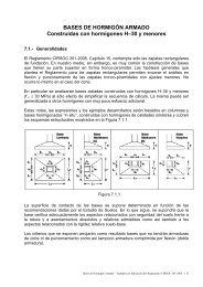
<strong>Reinforced</strong> concrete floor<br />
systems can provide an<br />
economical solution to a<br />
wide variety <strong>of</strong> situations. Numerous types <strong>of</strong><br />
nonprestressed and prestressed floor systems<br />
are available to satisfy virtually any span and<br />
loading condition, see Figure 1. Selecting the<br />
most effective system for a given set <strong>of</strong><br />
constraints can be vital to achieving overall<br />
economy, especially for low- and mid-rise<br />
buildings and for buildings subjected to relatively<br />
low lateral forces where the cost <strong>of</strong> the<br />
lateral-force-resisting system is minimal.<br />
General considerations<br />
Concrete, reinforcement, and formwork are the three<br />
primary expenses in cast-in-place concrete floor construction<br />
to consider throughout the design process, but especially<br />
during the initial planning stages. Of these three,<br />
formwork comprises about 50 to 60 percent <strong>of</strong> the total cost<br />
Continuing Education<br />
The Pr<strong>of</strong>essional Development Series is a unique opportunity<br />
to earn continuing education credit by reading specially<br />
focused, sponsored articles in Structural Engineer. If you read<br />
the following article, display your understanding <strong>of</strong> the stated<br />
learning objectives, and follow the simple instructions, you can<br />
fulfill a portion <strong>of</strong> your continuing education requirements at<br />
no cost to you.<br />
Instructions<br />
First, review the learning objectives below, then read the<br />
Pr<strong>of</strong>essional Development Series article. Next complete the<br />
quiz and submit your answers to the Pr<strong>of</strong>essional<br />
Development Series sponsor. Submittal instructions are<br />
provided on the Reporting Form, which follows the quiz and is<br />
also available for download at www.gostructural.com/se-pdh.<br />
Your quiz answers will be graded by the Pr<strong>of</strong>essional<br />
Development Series sponsor. If you answer at least 80 percent<br />
<strong>of</strong> the questions correctly, you will receive a certificate <strong>of</strong><br />
completion from the Pr<strong>of</strong>essional Development Series sponsor<br />
within 90 days and will be awarded 2.0 pr<strong>of</strong>essional development<br />
hour (equivalent to 0.2 continuing education unit in<br />
most states).<br />
Note: It is the responsibility <strong>of</strong> the licensee to determine if this<br />
method <strong>of</strong> continuing education meets his or her governing<br />
board(s) <strong>of</strong> registration’s requirements.<br />
Learning Objectives<br />
This tutorial focuses on cast-in-place concrete floor systems<br />
with nonprestressed reinforcement. The reader will learn<br />
methods <strong>of</strong> analysis and design for these types <strong>of</strong> floor systems<br />
that satisfy The American Concrete Institute’s Building Code<br />
Requirements for Structural Concrete (ACI 318-05). All referenced<br />
items are from ACI 318-05, unless noted otherwise.<br />
Pr<strong>of</strong>essional Development Series Sponsor<br />
Portland Cement Association<br />
a<br />
c<br />
e<br />
b<br />
d<br />
Figure 1: Cast-in-place reinforced<br />
concrete floor systems (a)<br />
flat plate, (b) flat slab, (c) oneway<br />
joist, (d) wide-module joist,<br />
and (e) two-way joist<br />
and has the greatest influence on the overall cost <strong>of</strong> the floor<br />
system. The cost <strong>of</strong> the concrete, including placing and<br />
finishing, typically accounts for about 25 to 30 percent <strong>of</strong><br />
the overall cost. The reinforcing steel has the lowest influence<br />
on overall cost.<br />
To achieve overall economy, designers should satisfy the<br />
following three basic principles <strong>of</strong> formwork economy:<br />
Specify readily available standard form sizes. Rarely will<br />
custom forms be economical, unless they are required in a<br />
quantity that allows for mass production.<br />
Repeat sizes and shapes <strong>of</strong> the concrete members<br />
wherever possible. Repetition allows reuse <strong>of</strong> forms from<br />
bay to bay and from floor to floor.<br />
Strive for simple formwork. In cast-in-place concrete<br />
construction, economy is rarely achieved by reducing quantities<br />
<strong>of</strong> materials. For example, varying the depth <strong>of</strong> a beam<br />
2 PDH Special Advertizing Section — Portland Cement Association
<strong>Design</strong> <strong>of</strong> <strong>Reinforced</strong> Concrete Floor Systems<br />
with the loading and span variations would give a moderate<br />
savings in materials, but would create substantial additional<br />
costs in formwork, resulting in a more expensive structure.<br />
The simplest and most cost-effective solution would be<br />
providing a constant beam depth and varying the reinforcement<br />
along the span. Simple formwork can make construction<br />
time shorter, resulting in a building that can be<br />
occupied sooner.<br />
Additional parameters must be considered when selecting<br />
an economical floor system. In general, span lengths, floor<br />
loads, and geometry <strong>of</strong> a floor panel all play a key role in the<br />
selection process. Detailed information on how to select<br />
economical concrete floor systems for a wide variety <strong>of</strong> situations<br />
can be found in the following Portland Cement<br />
Association (PCA) publications: Concrete Floor Systems —<br />
Guide to Estimating and Economizing (SP041), and Long-<br />
Span Concrete Floor Systems (SP339).<br />
Preliminary sizing<br />
Before analyzing the floor system, designers must assume<br />
preliminary member sizes. Typically, the slab and/or beam<br />
thickness is determined first to ensure that the deflection<br />
requirements <strong>of</strong> Section 9.5 are satisfied.<br />
For solid, one-way slabs and beams that are not supporting<br />
or attached to partitions or other construction likely to be<br />
damaged by large deflections, Table 9.5(a) may be used to<br />
determine minimum thickness, h. For continuous one-way<br />
slabs and beams, determine h based on one end continuous,<br />
since this thickness will satisfy deflection criteria for all spans.<br />
The preliminary thickness <strong>of</strong> a solid one-way slab with normal<br />
weight concrete and Grade 60 reinforcement is l/24, where<br />
l is the span length in inches. Similarly, for beams, minimum<br />
h is l/18.5. Deflections need not be computed when a thickness<br />
at least equal to the minimum is provided.<br />
For nonprestressed, two-way slabs, minimum thickness<br />
requirements are given in Section 9.5.3. By satisfying these<br />
minimum requirements, which are illustrated in Figure 2 for<br />
Grade 60 reinforcement, deflections need not be computed.<br />
Deflection calculations for two-way slabs are complex, even<br />
when linear elastic behavior is assumed. In Figure 2, α f is the<br />
ratio <strong>of</strong> the flexural stiffness <strong>of</strong> a beam section to the flexural<br />
stiffness <strong>of</strong> a width <strong>of</strong> slab bounded laterally by centerlines <strong>of</strong><br />
adjacent panels (see Section 13.6.1.6), and α fm is the average<br />
value <strong>of</strong> α f for all beams on the edges <strong>of</strong> a panel. For two-way<br />
construction, l n is the clear span length in the long direction<br />
measured face-to-face <strong>of</strong> supports.<br />
When two-way slab systems are supported directly on<br />
columns, shear around the columns is critically important,<br />
especially at exterior slab-column connections where the<br />
total exterior slab moment must be transferred directly to the<br />
column. Minimum slab thickness for flat plates <strong>of</strong>ten is<br />
governed by this condition.<br />
Once the depth <strong>of</strong> a beam has been computed, the width<br />
b w can be determined based on moment strength. The<br />
following equation, which is derived in the PCA’s Simplified<br />
<strong>Design</strong> (EB104) Handbook, can be used to<br />
determine b w for the typical case when<br />
f ’ c = 4,000 pounds per square inch (psi) and<br />
f y = 60 kips per square inch (ksi):<br />
In this equation, M u is the largest factored moment along<br />
the span (foot-kips) and d is the required effective depth <strong>of</strong><br />
the beam (inches), based on deflection criteria. For beams<br />
with one layer <strong>of</strong> reinforcement, d can be taken equal to<br />
h – 2.5 inches, while for joists and slabs, d can be taken as<br />
h – 1.25 inches. Similar sizing equations can be derived for<br />
other concrete strengths and grades <strong>of</strong> reinforcement.<br />
In the preliminary design stage, it is important for the<br />
engineer to consider fire resistance. Building codes regulate<br />
the fire resistance <strong>of</strong> the various elements and assemblies <strong>of</strong><br />
a building structure. Fire resistance must be considered<br />
when choosing a slab thickness. Table 721.2.2.1 in the<br />
International Code Council’s 2003 International Building<br />
Code (IBC) contains minimum reinforced concrete slab<br />
thickness for fire-resistance ratings <strong>of</strong> one to four hours,<br />
based on the type <strong>of</strong> aggregate used in the concrete mix. In<br />
general, concrete member thickness required for structural<br />
purposes is usually adequate to provide at least a two-hour<br />
fire-resistance rating. Adequate cover to the reinforcing steel<br />
is required to protect it from the effects <strong>of</strong> fire. Cover thicknesses<br />
for reinforced concrete floor slabs and beams are<br />
given in IBC Tables 721.2.3(1) and 721.2.3(3), respectively.<br />
The minimum cover requirements in Section 7.7.1 <strong>of</strong> ACI<br />
14<br />
13<br />
12<br />
11<br />
10<br />
9<br />
8<br />
7<br />
6<br />
5<br />
4<br />
Flat plate<br />
b w = 20 M u / d<br />
Flat plate with spandrel<br />
beams* and flat slab<br />
Flat slab with<br />
spandrel beams*<br />
Two-way beam-supported<br />
slab (β = 1) * , **<br />
Two-way beam-supported<br />
slab (β = 2) * , **<br />
3<br />
10 15 20 25 30 35 40<br />
Longer Clear Span (ft)<br />
*Spandrel beam-to-slab stiffness ratio α ≥ 0.8<br />
**α m > 2.0<br />
Figure 2: Minimum slab thickness for two-way slab systems<br />
2<br />
Special Advertizing Section — Portland Cement Association PDH 3
<strong>Design</strong> <strong>of</strong> <strong>Reinforced</strong> Concrete Floor Systems<br />
318-05 will provide at least a two-hour fireresistance<br />
rating. In all cases, the local building<br />
code governing the specific project must<br />
be consulted to ensure that minimum fireresistance<br />
requirements are met.<br />
Uniformly Distributed Loading (L/D 2)<br />
l 1 ( 2/3)l 1<br />
l 1<br />
Three or More Spans<br />
Uniformly Distributed Load ( L/D≤ 3)<br />
≤ 1.2 l n<br />
l n<br />
Prismatic<br />
Members<br />
Rectangular slab<br />
panels (2 or less: 1)<br />
Column <strong>of</strong>fset<br />
l 2 /10<br />
l 2<br />
Figure 3: Conditions for analysis by coefficients <strong>of</strong> ACI Section<br />
8.3.3<br />
Analysis methods<br />
Section 8.3 contains criteria for analyzing continuous<br />
beams and one-way slabs. In general, all members <strong>of</strong> frames<br />
or continuous construction must be designed for the maximum<br />
effects <strong>of</strong> factored loads, per Section 9.2, using an elastic<br />
analysis. Even though numerous computer programs exist<br />
that can accomplish this task, the set <strong>of</strong> approximate coefficients<br />
in Section 8.3.3 can be used to determine moments<br />
and shear forces, provided the limitations in Figure 3 are satisfied.<br />
These coefficients, which are given in Figure 4, provide a<br />
quick and conservative way <strong>of</strong> determining design forces for<br />
beams and one-way slabs, and can be used to check output<br />
from a computer program.<br />
Simple<br />
Support<br />
Simple<br />
Support<br />
l n<br />
W u l 2 n<br />
11<br />
End Span<br />
l n<br />
w u l 2 n*<br />
10<br />
*w u l 2 n<br />
9<br />
l n l n<br />
Integral<br />
with<br />
Support<br />
w u l 2 n w u l 2 n w u l 2 n*<br />
11 11 10<br />
(2spans)<br />
l n<br />
W u l 2 n<br />
16<br />
Interior Span<br />
Positive Moments—All Cases<br />
Negative Moments—All Cases<br />
l n<br />
W u l 2 n<br />
14<br />
End Span<br />
w u l 2 n<br />
24<br />
w u l 2 n<br />
16<br />
Integral<br />
with<br />
Support<br />
Spandrel<br />
Support<br />
Column<br />
Support<br />
Figure 5: Conditions for analysis by the Direct <strong>Design</strong> Method<br />
systems. If the limitations <strong>of</strong> the Direct <strong>Design</strong> Method in<br />
Section 13.6.1 are met (see Figure 5), then the total factored<br />
static moment M o for a span can be distributed as negative<br />
and positive moments in the column and middle strips in<br />
accordance with Sections 13.6.3, 13.6.4, and 13.6.6, where<br />
2<br />
qu<br />
l 2 l n<br />
Mo<br />
=<br />
8<br />
And q u = factored load per unit area; l 2 = length <strong>of</strong> span,<br />
measured center-to-center <strong>of</strong> supports, in the direction<br />
perpendicular to the direction moments are being determined;<br />
and l n = length <strong>of</strong> clear span, measured face-to-face<br />
<strong>of</strong> supports, in the direction moments are being determined<br />
(Section 13.6.2.5).<br />
Flat Plate or Flat Slab Supported Directly on Columns<br />
End Span<br />
Interior Span<br />
1<br />
2<br />
3<br />
4<br />
5<br />
Slab Moments Exterior<br />
First Interior<br />
Interior<br />
Negative Positive Negative Positive Negative<br />
Total Moment 0.26 Mo 0.52 Mo 0.70 Mo 0.35 Mo 0.65 Mo<br />
Column Strip 0.26 Mo 0.31 Mo 0.53 Mo 0.21 Mo 0.49 Mo<br />
Middle Strip 0 0.21 Mo 0.17 Mo 0.14 Mo 0.16 Mo<br />
Note: All negative moments are at face <strong>of</strong> support.<br />
End Span<br />
Interior Span<br />
1 2 3 4 5<br />
Simple<br />
Support<br />
w u l n<br />
2<br />
l n<br />
End Span<br />
1.15w u l n<br />
2<br />
l n l n<br />
Integral<br />
w with<br />
u l n w u l n 1.15w u l n w u l n<br />
Support<br />
2 2<br />
2 2<br />
Interior Span<br />
End Span<br />
End Shears—All Cases<br />
Figure 4: Analysis by coefficients <strong>of</strong> ACI Section 8.3.3<br />
In lieu <strong>of</strong> an analysis procedure satisfying equilibrium and<br />
geometric compatibility, the Direct <strong>Design</strong> Method <strong>of</strong><br />
Section 13.6 or the Equivalent Frame Method <strong>of</strong> Section 13.7<br />
can be used to obtain design moments for two-way slab<br />
Figure 6: <strong>Design</strong> moment coefficients used with the Direct<br />
<strong>Design</strong> Method for flat plates or flat slabs supported directly on<br />
columns<br />
Figures 6 and 7 summarize the moments in the column<br />
and middle strips along the span <strong>of</strong> flat plates or flat slabs<br />
supported directly on columns and flat plates or flat slabs<br />
with spandrel beams, respectively.<br />
<strong>Design</strong> for flexure<br />
The required amount <strong>of</strong> flexural reinforcement is calculated<br />
using the design assumptions <strong>of</strong> Section 10.2 and the<br />
4 PDH Special Advertizing Section — Portland Cement Association
<strong>Design</strong> <strong>of</strong> <strong>Reinforced</strong> Concrete Floor Systems<br />
Flat Plate or Flat Slab with Spandrel Beams<br />
End Span<br />
Interior Span<br />
1<br />
2<br />
3<br />
4<br />
5<br />
Slab Moments Exterior<br />
First Interior<br />
Interior<br />
Negative Positive Negative Positive Negative<br />
Total Moment 0.30 Mo 0.50 Mo 0.70 Mo 0.35 Mo 0.65 Mo<br />
Column Strip 0.23 Mo 0.30 Mo 0.53 Mo 0.21 Mo 0.49 Mo<br />
Middle Strip 0.07 Mo 0.20 Mo 0.17 Mo 0.14 Mo 0.16 Mo<br />
Note:<br />
(1) All negative moments are at face <strong>of</strong> support.<br />
(2) Torsional stiffness <strong>of</strong> spandrel beams t 2.5. For values <strong>of</strong> t less than 2.5,<br />
exterior negative column strip moment increases to (0.30 ñ 0.03 t) Mo.<br />
End Span<br />
Interior Span<br />
1 2 3 4 5<br />
Figure 7: <strong>Design</strong> moment coefficients used with the Direct<br />
<strong>Design</strong> Method for flat plates or flat slabs with spandrel beams<br />
general principles and requirements <strong>of</strong> Section 10.3, based<br />
on the factored moments from the analysis. In typical cases,<br />
beams, one-way slabs, and two-way slabs will be tensioncontrolled<br />
sections, so that the strength reduction factor φ is<br />
equal to 0.9 in accordance with Section 9.3. In such cases,<br />
the required amount <strong>of</strong> flexural reinforcement A s at a section<br />
can be determined from the following equation, which is<br />
derived in PCA’s Simplified <strong>Design</strong> for f ’ c = 4,000 psi and<br />
f y = 60 ksi:<br />
M u<br />
A s =<br />
4 d<br />
where M u is the factored bending moment at the section<br />
(foot-kips) and d is the distance from the extreme compression<br />
fiber to the centroid <strong>of</strong> the longitudinal tension reinforcement<br />
(inches). For greater concrete strengths, this<br />
equation yields slightly conservative results. The required A s<br />
must be greater than or equal to the minimum area <strong>of</strong> steel<br />
and less than or equal to the maximum area <strong>of</strong> steel.<br />
For beams, the minimum area <strong>of</strong> steel A s, min is given in<br />
Section 10.5.1:<br />
3 f ′<br />
c b w d 200 b w d<br />
A s, min =<br />
≥<br />
fy<br />
fy<br />
The equation for A s, min need not be satisfied where the<br />
provided A s at every section is greater than one-third that<br />
required by analysis.<br />
For one-way slabs, A s, min in the direction <strong>of</strong> the span is the<br />
same as the minimum area <strong>of</strong> steel for shrinkage and<br />
temperature reinforcement, which is 0.0216h per foot width<br />
<strong>of</strong> slab for Grade 60 reinforcement (Section 10.5.4). The<br />
maximum spacing <strong>of</strong> the reinforcement is 3h or 18 inches,<br />
whichever is less.<br />
For two-way slabs, the minimum reinforcement ratio in<br />
each direction is 0.0018 for Grade 60 reinforcement (Section<br />
13.3). In this case, the maximum spacing is 2h or 18 inches.<br />
A maximum reinforcement ratio for beams and slabs is not<br />
directly given in ACI 318-05. Instead, Section 10.3.5 requires<br />
that nonprestressed flexural members must be designed such<br />
that the net tensile strain in the extreme layer <strong>of</strong> longitudinal<br />
tension steel at nominal strength ε t is<br />
greater than or equal to 0.004. In essence,<br />
this requirement limits the amount <strong>of</strong> flexural<br />
reinforcement that can be provided at a<br />
section. Using a strain compatibility analysis for<br />
4,000-psi concrete and Grade 60 reinforcement, the maximum<br />
reinforcement ratio is 0.0206.<br />
When selecting bar sizes, it is important to consider the<br />
minimum and maximum number <strong>of</strong> reinforcing bars that are<br />
permitted in a cross-section. The limits are a function <strong>of</strong> the<br />
following requirements for cover and spacing:<br />
• Sections 7.6.1 and 3.3.2 (minimum spacing for concrete<br />
placement);<br />
• Section 7.7.1 (minimum cover for protection <strong>of</strong> reinforcement);<br />
and<br />
• Section 10.6 (maximum spacing for control <strong>of</strong> flexural<br />
cracking).<br />
The maximum spacing <strong>of</strong> reinforcing bars is limited to the<br />
value given by Equation (10-4) in Section 10.6.4. The following<br />
equation can be used to determine the minimum<br />
number <strong>of</strong> bars n min required in a single layer:<br />
bw<br />
− 2 ( c c + 0.5d<br />
b )<br />
nmin = s + 1<br />
The bar spacing s is given by Equation (10-4):<br />
⎛<br />
⎞<br />
40,000<br />
40, 000<br />
s = 15<br />
− ≤<br />
⎜<br />
⎟ 2.5 c<br />
⎜<br />
c 12<br />
f<br />
⎟ ⎝ s<br />
f<br />
⎠<br />
⎝ s<br />
⎠<br />
In these equations, c c is the least distance from the surface<br />
<strong>of</strong> the reinforcement to the tension face <strong>of</strong> the section, d b is<br />
the nominal diameter <strong>of</strong> the reinforcing bar, and f s is the<br />
calculated tensile stress in the reinforcement at service loads,<br />
which can be taken equal to 2 f y / 3. The values obtained<br />
from the above equation for n min should be rounded up to<br />
the next whole number.<br />
The maximum number <strong>of</strong> bars n max permitted in a section<br />
can be computed from the following equation:<br />
bw<br />
− 2 ( c s + d s + r)<br />
n max =<br />
+ 1<br />
( Minimum clear space) + db<br />
where c s = clear cover to the stirrups; d s = diameter <strong>of</strong> stirrup<br />
reinforcing bar; r = 0.75 inch for No. 3 stirrups, or<br />
1.0 inch for No. 4 stirrups; and clear space is the largest <strong>of</strong><br />
1 inch, d b , or 1.33 (maximum aggregate size).<br />
Computed values <strong>of</strong> n max from this equation should be<br />
rounded down to the next whole number.<br />
<strong>Design</strong> for shear<br />
<strong>Design</strong> provisions for shear are given in Chapter 11. A<br />
summary <strong>of</strong> the one-way shear provisions is given in Table 1.<br />
These provisions are applicable to normal-weight concrete<br />
members subjected to shear and flexure only with Grade 60<br />
shear reinforcement. The strength reduction factor φ = 0.75<br />
per Section 9.3.2 and V f b d per Equation (11-3).<br />
c = 2 ′<br />
c w<br />
⎛<br />
⎞<br />
Special Advertizing Section — Portland Cement Association PDH 5
<strong>Design</strong> <strong>of</strong> <strong>Reinforced</strong> Concrete Floor Systems<br />
Both one-way<br />
shear and two-way<br />
shear must be investigated<br />
in two-way<br />
floor systems.<br />
One-way shear — <strong>Design</strong> for<br />
one-way shear, which rarely<br />
governs, consists <strong>of</strong> checking that<br />
the following equation is satisfied at<br />
critical sections located a distance d<br />
from the face <strong>of</strong> the support (see<br />
Figure 8):<br />
Vu<br />
≤ φ 2<br />
f ′<br />
c ld<br />
where l is equal to l 1 or l 2 and<br />
V u is the corresponding shear force<br />
at the critical section.<br />
Two-way shear — As<br />
noted previously, twoway<br />
or punching shear<br />
usually is more critical<br />
than one-way shear in<br />
slab systems supported<br />
directly on columns. As<br />
shown in Figure 8, the<br />
critical section for twoway<br />
action is at a<br />
distance <strong>of</strong> d/2 from<br />
edges or corners <strong>of</strong><br />
columns, concentrated<br />
loads, reaction areas,<br />
and changes in slab<br />
thickness, such as edges<br />
<strong>of</strong> column capitals or<br />
˜2<br />
˜2<br />
Required area<br />
area <strong>of</strong><br />
stirrups, A v<br />
Critical<br />
section<br />
(a) Beam shear<br />
C L<br />
C L<br />
panels<br />
panels<br />
drop panels. For nonprestressed slabs <strong>of</strong> normal-weight<br />
concrete without shear reinforcement, the following must<br />
be satisfied (Section 11.12.2):<br />
Table 1: ACI 318-05 provisions for shear design<br />
l 1<br />
d<br />
l 1<br />
Critical<br />
section<br />
d/2<br />
None<br />
Required —<br />
Stirrup<br />
spacing,<br />
s<br />
Maximum —<br />
(b) Two-way shear<br />
Figure 8: Critical sections for oneway<br />
and two-way shear<br />
Vu ≤ φ V c / 2 φ Vc<br />
≥ Vu<br />
> φ Vc<br />
/ 2<br />
0 .75 f c′<br />
bw<br />
s<br />
≥<br />
50 bw<br />
s<br />
f yt<br />
fyt<br />
c 2 + 1.5 (slab or drop panel thickness on each side <strong>of</strong> the<br />
column or capital). Reinforcement is concentrated in the<br />
effective slab width such that φ M n ≥γ f M u .<br />
The portion <strong>of</strong> M u transferred by eccentricity <strong>of</strong> shear is<br />
γ v M u = (1 - γ f )M u (Sections 13.5.3.1 and 11.12.6). When the<br />
Direct <strong>Design</strong> Method is used, the gravity load moment M u<br />
to be transferred between slab and edge column must be<br />
0.3M o (Section 13.6.3.6).<br />
The factored shear forces on the faces <strong>of</strong> the critical section<br />
AB and CD are as follows (Section 11.12.6.2):<br />
where A c is the area <strong>of</strong> the critical section and J c / c AB and<br />
J c / c CD are the section moduli <strong>of</strong> the critical section.<br />
Numerous resources are available that give equations for A c ,<br />
J c / c AB , and J c / c CD , including PCA’s Simplified <strong>Design</strong>.<br />
Vu<br />
( Vu<br />
> φ Vc<br />
− φ Vc<br />
) s<br />
φ fyt<br />
d<br />
A v fyt<br />
A v fyt<br />
φ A v fyt<br />
d<br />
≤<br />
0 .75 f ′ b<br />
c b 50<br />
w<br />
w<br />
Vu<br />
− φ Vc<br />
d / 2 ≤<br />
24 inches<br />
vu<br />
( AB )<br />
vu<br />
( CD )<br />
Vu<br />
=<br />
A c<br />
Vu<br />
=<br />
A c<br />
d / 2 ≤ 24 inches for<br />
( V u − φ Vc ) ≤ 4 φ fc′<br />
bw<br />
d<br />
d<br />
/ 4<br />
≤ 12<br />
( Vu<br />
− φ Vc<br />
) ><br />
γ v Mu<br />
c AB<br />
+<br />
Jc<br />
γ v Mu<br />
c CD<br />
−<br />
Jc<br />
inches for<br />
4 φ<br />
fc′<br />
bw<br />
d<br />
vu<br />
≤ φ vc<br />
= smallest <strong>of</strong><br />
⎧ ⎛ 4 ⎞<br />
⎪ φ<br />
′<br />
⎪<br />
⎜ 2 +<br />
⎟ f c<br />
⎝<br />
β<br />
⎠<br />
⎪<br />
⎪<br />
⎪ ⎛ α ⎞<br />
s d<br />
⎨ φ ⎜ + 2 ⎟<br />
⎪ ⎝ bo<br />
⎠<br />
⎪<br />
⎪<br />
⎪ φ 4 f ′<br />
⎪ c<br />
⎩<br />
where v u is the maximum factored shear stress at the critical<br />
section and all other variables are defined in Chapter 2.<br />
Moment transfer — Transfer <strong>of</strong> moment in slab-column<br />
connections takes place by a combination <strong>of</strong> flexure (Section<br />
13.5.3) and eccentricity <strong>of</strong> shear (Section 11.12.6). The<br />
portion <strong>of</strong> total unbalanced moment M u transferred by flexure<br />
is γ f M u , where γ f is defined in Equation (13-1) as a function<br />
<strong>of</strong> the critical section dimensions b 1 and b 2 . It is assumed<br />
that γ f M u is transferred within an effective slab width equal to<br />
f ′<br />
c<br />
Summary<br />
The above discussion summarized the design requirements<br />
<strong>of</strong> concrete floor systems with nonprestressed reinforcement<br />
according to ACI 318-05. It is important to note<br />
that once the required flexure and shear reinforcement have<br />
been determined, the reinforcing bars must be developed<br />
properly in accordance with the provisions in Chapters 12<br />
and 13. The structural integrity requirements <strong>of</strong> Section 7.13<br />
must be satisfied as well.<br />
Detailed, worked-out example problems that illustrate the<br />
material presented in this paper can be found on the PCA<br />
web site at www.cement.org/buildings/design_aids.asp.<br />
David A. Fanella, Ph.D., S.E., P.E., is project manager, Graef, Anhalt,<br />
Schloemer & Associates, Inc., Chicago. He can be contacted via e-mail at<br />
david.a.fanella@gasai.com. Iyad M. Alsamsam, Ph.D., S.E., P.E., is manager,<br />
Buildings and Special Structures, Portland Cement Association, Skokie, Ill. He can<br />
be contacted via e-mail at alsamsam@cement.org.<br />
6 PDH Special Advertizing Section — Portland Cement Association
Structural Engineer’s Pr<strong>of</strong>essional Development Series Quiz<br />
Pr<strong>of</strong>essional Development Series Sponsor: Portland Cement Association<br />
5420 Old Orchard Road, Skokie, IL 60077<br />
(847) 972-9058 • Fax: (847) 972-9059 • Email: info@cement.org • www.cement.org<br />
Questions<br />
1. Problem 1: A five-span continuous reinforced concrete beam has<br />
exterior spans equal to 30 feet and interior spans <strong>of</strong> 25 feet. All spans are<br />
measured center-to-center <strong>of</strong> supports. Exterior columns are 20 x 20<br />
inches and interior columns are 24 x 24 inches. The beam supports a<br />
service dead load <strong>of</strong> 3,250 pounds per linear foot (plf) and a service live<br />
load <strong>of</strong> 2,000 plf. Neglect the weight <strong>of</strong> the beam. Concrete is normalweight<br />
with f ’ c = 4,000 pounds per square inch (psi), and reinforcing<br />
steel is Grade 60, f y = 60 kips per square inch (ksi). The minimum beam<br />
depth that would satisfy the deflection criteria <strong>of</strong> Section 9.5 for all<br />
spans is nearest to<br />
a) 16 inches b) 17 inches c) 20 inches d) 22 inches<br />
2. For the system described in Problem 1, assume a beam depth <strong>of</strong> 24<br />
inches. The minimum width <strong>of</strong> the beam that can be used for all spans<br />
based on moment strength is nearest to<br />
a) 16 inches b) 20 inches c) 22 inches d) 24 inches<br />
3. For the system described in Problem 1, assume a 28-inch-wide by 24-<br />
inch-deep beam. The required area <strong>of</strong> negative flexural reinforcement<br />
required at the supports <strong>of</strong> the middle span is nearest to<br />
a) 2.50 inches 2 b) 3.00 inches 2 c) 3.25 inches 2 d) 4.0 inches 2<br />
4. For the system described in Problem 1, assume a 24-inch-wide by 22-<br />
inch-deep beam. Using No. 4 U-stirrups, the required spacing <strong>of</strong> the stirrups<br />
at the critical section <strong>of</strong> the first interior support is nearest to<br />
a) 5.0 inches b) 6.0 inches c) 8.0 inches d) 10.0 inches<br />
5. The exterior panel <strong>of</strong> a concrete floor system consisting <strong>of</strong> a slab with<br />
beams spanning between the supports on all sides has center-to-center<br />
spans <strong>of</strong> 22 feet and 25 feet. It is supported by columns that are 22 x 22<br />
inches. All beams are 22 inches wide by 24 inches deep. Preliminary<br />
design indicates that the beam-to-slab flexural stiffness ratios α f for the<br />
beams are 4.65, 5.23, 2.92, and 3.32. Assume Grade 60 reinforcement<br />
(f y = 60 ksi). The minimum slab thickness that would satisfy the deflection<br />
criteria <strong>of</strong> Section 9.5.3 is nearest to<br />
a) 3.5 inches b) 5.0 inches c) 6.0 inches d) 7.0 inches<br />
6. Problem 6: The interior panel <strong>of</strong> a flat plate floor system has centerto-center<br />
span lengths <strong>of</strong> 20 feet and 18 feet. Columns are 20 x 20<br />
inches. Assume normal-weight concrete with f ’ c = 4,000 psi and Grade<br />
60 reinforcement. Use a preliminary slab thickness <strong>of</strong> 7.5 inches (effective<br />
d = 6.25 inches). Superimposed dead load = 20 pounds per square<br />
foot (psf), and service live load = 40 psf. The factored, one-way shear<br />
force V u at the critical section <strong>of</strong> a 1-foot-wide design strip is nearest to<br />
a) 1.7 kips b) 2.5 kips c) 5.3 kips d) 20.4 kips<br />
7. For the system described in Problem 6, the factored, two-way shear<br />
force V u at the critical section <strong>of</strong> an interior column is nearest to<br />
a) 50.5 kips b) 71.0 kips c) 85.6 kips d) 99.4 kips<br />
8. For the system described in Problem 6, the allowable two-way shear<br />
force φV c is nearest to<br />
a) 75.5 kips b) 85.3 kips c) 94.2 kips d) 124.5 kips<br />
9. For the system described in Problem 6, it has been determined that<br />
the Direct <strong>Design</strong> Method <strong>of</strong> Section 13.6 can be used. For a design<br />
strip along the 20-foot span direction ( l 1 = 20 feet), the total factored<br />
static moment M o is nearest to<br />
a) 151 ft-kips b) 175 ft-kips c) 199 ft-kips d) 225 ft-kips<br />
10. For the system described in Problem 6, the required area <strong>of</strong> flexural<br />
reinforcement in the column strip at an interior support in an interior<br />
span is nearest to<br />
a) 1.5 inches 2 b) 1.9 inches 2 c) 2.2 inches 2 d) 3.0 inches 2<br />
Structural Engineer’s Pr<strong>of</strong>essional Development Series Reporting Form<br />
Article Title: <strong>Design</strong> <strong>of</strong> <strong>Reinforced</strong> Concrete Floor Systems<br />
Sponsor: Portland Cement Association Valid for credit until: September 2007<br />
Instructions: Select one answer for each quiz question and clearly circle the appropriate letter. Provide all <strong>of</strong> the requested contact information. Fax<br />
this Reporting Form to (847) 972-9059. (You do not need to send the Quiz; only this Reporting Form is necessary to be submitted.)<br />
1) a b c d 6) a b c d<br />
2) a b c d 7) a b c d<br />
3) a b c d 8) a b c d<br />
4) a b c d 9) a b c d<br />
5) a b c d 10) a b c d<br />
Required contact information<br />
Last Name: First Name: Middle Initial:<br />
Title:<br />
Firm Name:<br />
Address:<br />
City: State: Zip:<br />
Telephone: Fax: E-mail:<br />
Certification <strong>of</strong> ethical completion: I certify that I read the article, understood the learning objectives, and completed the quiz questions to the<br />
best <strong>of</strong> my ability. Additionally, the contact information provided above is true and accurate.<br />
Signature:<br />
Date:<br />
Special Advertizing Section — Portland Cement Association PDH 7