Solutions to Chapter 4 - Communication Networks
Solutions to Chapter 4 - Communication Networks
Solutions to Chapter 4 - Communication Networks

You also want an ePaper? Increase the reach of your titles
YUMPU automatically turns print PDFs into web optimized ePapers that Google loves.
<strong>Communication</strong> <strong>Networks</strong> (2 nd Edition)<br />
<strong>Chapter</strong> 4 <strong>Solutions</strong><br />
which is 4x 1/3 x 80% STS-3 or 16/15 STS-3. Adding the other 20% of the traffic which is<br />
destined <strong>to</strong> the higher tier link and has <strong>to</strong> traverse some of the lower tier links in both directions,<br />
the average link capacity in the lower tier links should be 16/15 STS-3 + 2 x 20% STS-3 or 22/15<br />
STS-3, which is almost 1.5 STS-3 on average.<br />
On the higher tier ring, the traffic from each subring will be routed equally <strong>to</strong> each other subring.<br />
Thus the bandwidth required on each link will be four times the average traffic between two<br />
subrings or 4 x 1/3 of the <strong>to</strong>tal traffic from each subring. Because each ring produces 4×0.2 ×<br />
STS-3 amount of traffic, the bandwidth required on each link of the higher tier ring is on the order<br />
of 4/3 × 0.8 × STS-3 ≈ STS-3.<br />
b. Discuss the bandwidth requirements that are possible if 80% of the traffic generated by each<br />
site is destined <strong>to</strong> sites in other rings.<br />
If 20% of the traffic is <strong>to</strong> stay within the same ring, then the required bandwidth on the higher tier<br />
ring will be increased. The required bandwidth on the lower tier rings will not change significantly,<br />
as each source still produces and receives STS-3 of traffic.<br />
The higher tier ring will now support 4 times more traffic. Thus, the bandwidth requirement is<br />
around STS-12.<br />
15. Compare the efficiency of BLSR and UPSR rings in the following two cases:<br />
a. All traffic originating at the nodes in the ring are destined for a given central node.<br />
Considering that the <strong>to</strong>tal capacity of working and protection lines in both BLSR and<br />
UPSR is the same, the <strong>to</strong>tal bandwidth utilized in both BLSR and UPSR in this scenario is<br />
the same. The difference is the distribution of the traffic and unused capacity across the<br />
ring in the two cases.<br />
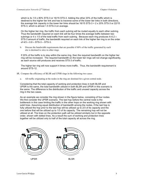
As an example we consider the ring shown in the figure below, consisting of four nodes.<br />
We first consider the UPSR scenario. The last hop before the central node is the<br />
bottleneck in this case limiting the traffic in the other hops on the working ring shown with<br />
solid lines. Assuming equal distribution of bandwidth among the nodes, if the last hop is<br />
fully utilized the hop prior <strong>to</strong> the last hop will be utilized up <strong>to</strong> 2/3 of its capacity and the<br />
one before that will be utilized up <strong>to</strong> 1/3 of its capacity. The remaining hop will not be<br />
utilized at all. The lines on the protection path will be utilized similarly but in the opposite<br />
order, shown with dotted lines. As a result the sum of working and protection lines<br />
<strong>to</strong>gether will be utilized only <strong>to</strong> half of the <strong>to</strong>tal capacity all across the ring.<br />
UPSR<br />
BLSR<br />
Leon-Garcia/Widjaja 8