Model 1250 Wheel Balancer - Atlantic Auto Suppliers
Model 1250 Wheel Balancer - Atlantic Auto Suppliers
Model 1250 Wheel Balancer - Atlantic Auto Suppliers

Create successful ePaper yourself
Turn your PDF publications into a flip-book with our unique Google optimized e-Paper software.
<strong>Model</strong> <strong>1250</strong><br />
<strong>Wheel</strong> <strong>Balancer</strong>
Instructions for use<br />
I<br />
CONTENTS<br />
page<br />
1 - GENERAL......................................................................................................................................................................3<br />
1.1 - GENERAL SAFETY RECOMMENDATIONS......................................................................................................3<br />
1.1.1 - STANDARD SAFETY DEVICES ...........................................................................................................3<br />
1.2 - FIELD OF APPLICATION....................................................................................................................................3<br />
1.3 - OVERALL DIMENSIONS....................................................................................................................................3<br />
1.4 - SPECIFICATION.................................................................................................................................................4<br />
2 - HANDLING AND HOISTING..........................................................................................................................................4<br />
3 - COMMISSIONING .........................................................................................................................................................4<br />
3.1 - ANCHORING......................................................................................................................................................4<br />
3.2 - ELECTRICAL CONNECTION.............................................................................................................................4<br />
3.3 - ADAPTER MOUNTING.......................................................................................................................................5<br />
3.4 - WHEEL GUARD ASSEMBLY AND ADJUSTMENT (OPTIONAL).......................................................................5<br />
3.5 - SPACER WD.......................................................................................................................................................5<br />
4 - CONTROLS AND COMPONENTS ..............................................................................................................................5<br />
4.1 - MANUAL RIM DISTANCE GAUGE ...................................................................................................................5<br />
4.2 - CONTROL PANEL AND DISPLAY......................................................................................................................6<br />
4.2.1 - OPERATION FUNCTIONS MENU........................................................................................................7<br />
5 - INDICATION AND USE OF THE WHEEL BALANCER ................................................................................................8<br />
5.1 - MANUAL PRESETTING OF WHEEL DIMENSIONS ........................................................................................8<br />
5.1.1 - STANDARD WHEELS...........................................................................................................................8<br />
5.1.2 - WHEEL ALU3........................................................................................................................................9<br />
5.1.3 - WHEEL ALU4......................................................................................................................................10<br />
5.1.4 - WHEEL ALU5......................................................................................................................................10<br />
5.1.5 - SETTING WITH GAUGE EXTENSION ( OPTIONAL ) ...................................................................... 11<br />
5.2 - RECALCULATION OF THE UNBALANCE ......................................................................................................12<br />
5.3 - RESULT OF MEASUREMENT ........................................................................................................................12<br />
5.3.1 - SPLIT FUNCTION (UNBALANCE SPREAD)......................................................................................13<br />
5.3.2 - UNBALANCE OPTIMIZATION............................................................................................................14<br />
5.3.3 - ALU AND STATIC MODES..................................................................................................................15<br />
5.3.4 - AUTOMATIC MINIMISATION OF STATIC UNBALANCE....................................................................16<br />
6 - SET UP .......................................................................................................................................................................17<br />
6.1 - SELF-DIAGNOSTICS.......................................................................................................................................17<br />
6.2 - SELF-CALIBRATION ......................................................................................................................................18<br />
6.3 - DISPLAY SAVER..............................................................................................................................................19<br />
7 - ERRORS .....................................................................................................................................................................20<br />
8 - ROUTINE MAINTENANCE..........................................................................................................................................21<br />
8.1 - TO REPLACE THE FUSES ............................................................................................................................21<br />
I 0495 GB -
I 0495 GB -
1- General<br />
1.1 - General safety recommendations<br />
- The wheel balancing machine should only be used by duly authorized and trained personnel.<br />
- The wheel balancing machine should not be used for purposes other than those described in the instruction<br />
manual.<br />
- Under no way should the wheel balancing machine be modified except for those modifications made explicitly<br />
by the manufacturer.<br />
- Never remove the safety devices. Any work on the machine should only be carried out by specialist personnel.<br />
- Avoid using strong jets of compressed air for cleaning.<br />
- Use alcohol to clean plastic panels or shelves (AVOID LIQUIDS CONTAINING SOLVENTS).<br />
- Before starting the wheel balancing cycle, make sure that the wheel is securely locked on the adapter.<br />
- The machine operator should avoid wearing loose clothing. Make sure that unauthorized personnel do not<br />
approach the machine during the spin cycle.<br />
- Avoid placing objects inside the base as they could impair the correct operation of the machine.<br />
1.1.1 - Standard safety devices<br />
- Stop push button for stopping the wheel under emergency conditions.<br />
- The wheel guard is not compulsory since the balancing speed is less than 100 RPM.<br />
1.2 - Field of application<br />
The machine is designed for balancing wheels of car, light commercial vehicles or motorcycle, weighing less than 165<br />
lbs. It can be operated in the temperature range of 32° to + 110° F.<br />
The following functions are provided: SPLIT; Unbalance optimization; Self diagnostics; Self-calibration.<br />
1.3 - Overall dimensions<br />
1<br />
48" 37"<br />
1222 937,5<br />
53"<br />
1350<br />
I 0495 GB -
1.4 - Specification<br />
Weight (excluding adapter)<br />
198 lbs<br />
Single-phase power supply<br />
115 V 60 Hz<br />
Protection class IP 54<br />
Max power consumption<br />
0,8 Kw<br />
Balancing speed<br />
< 100 RPM<br />
Cycle time for average wheel (30 lb)<br />
6-8 seconds<br />
Max.resolution of measurement<br />
1 gram<br />
Position resolution ± 1.4 °<br />
Average noise<br />
< 70dB (A)<br />
Rim-machine distance<br />
0 - 252 mm<br />
Rim width setting range 1.5” - 20”<br />
Diameter setting range 10” - 30”<br />
2 - Handling and lifting<br />
2 2a<br />
NOTE: DO NOT RAISE THE MACHINE USING DIFFERENT LIFTING POINTS.<br />
3 - Commissioning<br />
3.1 - Anchoring<br />
The machine can operate on any flat non resilient floor.<br />
Make sure that the machine rests solely on the three support points provided (fig.2a).<br />
It is advisable to secure the system to the ground using the specific feet (see Figure 2a) in the event of<br />
continual use with wheels weighing over 75 lbs.<br />
3.2 - Electrical connection<br />
The machine is supplied with a 110V grounding plug.<br />
The supply voltage is given on the machine nameplate. It cannot be changed.<br />
Connection to the mains should always be made by expert personnel.<br />
The machine should not be started up without proper grounding.<br />
Connection to the mains should be through a slow acting safety switch rated at 8 A (115V). See enclosed layout.<br />
I 0495 GB -
3.3 - Adapter mounting<br />
2a<br />
A<br />
B<br />
The wheel balancing machine is supplied complete with<br />
cone adapter for fastening wheels with central bore. Other<br />
optional adapters can be mounted:<br />
a) Remove threaded end piece A after backing off screw<br />
B.<br />
b) Mount the new adapter (see enclosed brochures)<br />
Note: CAREFULLY CLEAN THE COUPLING<br />
SURFACES BEFORE PERFORMING ANY<br />
OPERATION.<br />
3.4 - <strong>Wheel</strong> guard assembly and adjustment (optional)<br />
a) Fasten the components to the base as described in the “GUARD INSTALLATION SEQUENCE” sheet attached at<br />
the end of the manual.<br />
c) With the guard closed check that the microswitch prod has slipped into place on the ring.<br />
d) Appropriately adjust the angular position of the control ring.<br />
Note: Do not lean on the guard during the wheel balancing cycle.<br />
3.5 - Spacer WD<br />
When balancing very wide wheels (9”), there is not enough space to turn the distance gauge. To withdraw the wheel<br />
from the machine side, fit spacer WD on the adapter body and secure it with the standard issue nuts. When centring<br />
the wheel with the cone on the inside, fit the DC spacer to obtain spring thrust.<br />
3<br />
DC WD Cone<br />
Spring<br />
4 - Controls and components<br />
4.1 - Manual rim distance gauge<br />
This gauge serves for manual measurement of the distance of the point of application of the counterweight from the<br />
machine.<br />
I 0495 GB -
4.2 - Control panel and display<br />
4<br />
5 6 7 8<br />
1 2<br />
9 10 11 12<br />
3 4<br />
13 14<br />
15 16 17<br />
1-2 Digital readouts, AMOUNT OF UNBALANCE,<br />
inside/outside<br />
3-4 Digital readouts, POSITION OF UNBALANCE,<br />
inside/outside<br />
5 Push button, FUNCTIONS MENU<br />
6 Menu selection confirmation pushbutton<br />
7 Push button, HOME<br />
8 Push button, SPLIT (unbalance resolution)<br />
9 DYNAMIC selection button<br />
10 Correction mode selection push button<br />
11 CORRECTION MODE display push button<br />
12 Push button, unbalance reading < 5 g (25 oz)<br />
13 Push button, emergency stop<br />
14 Push button, cycle start<br />
15 Push buttons, manual DISTANCE setting<br />
16 Push buttons, manual DIAMETER setting<br />
17 Push buttons, manual WIDTH setting<br />
Note:<br />
- Press buttons only with your fingers. Never use the weight pliers or other pointed objects.<br />
I 0495 GB -
4.2.1 - Operation functions menu<br />
ON/OFF<br />
Truck<br />
round/off<br />
CONFIRM<br />
See OPTIMIZATION UNBALANCE SECTION<br />
diameter<br />
mm/inch<br />
mm/inch<br />
width<br />
start from<br />
guard closing<br />
approx.<br />
1-5g or .1-<br />
.25oz<br />
CONFIRM<br />
CONFIRM<br />
CONFIRM<br />
CONFIRM<br />
See SELF-DIAGNOSTICS<br />
See SELF-CALIBRATION<br />
g/oz unbalance<br />
measurement unit<br />
Display saver<br />
operating time<br />
in minutes<br />
CONFIRM<br />
CONFIRM<br />
RETURN TO MEASUREMENT SCREEN<br />
I 0495 GB -
5 - Indication and use of the wheel balancer<br />
5.1 - Manual presetting of wheel dimensions<br />
5.1.1 - Standard wheels<br />
5<br />
b<br />
lettura<br />
reading<br />
a<br />
d<br />
- Preset distance “a” for the inside of the wheel from the<br />
machine.<br />
- Preset the nominal diameter “d” indicated on the tire.<br />
- Set the rated width, which is generally indicated on the rim,<br />
or measure width “b” using the compass gauge supplied.<br />
I 0495 GB -
5.1.2 - <strong>Wheel</strong> ALU 3<br />
- Measure the dimensions as shown in the following diagram.<br />
6<br />
0 gauge<br />
14 mm<br />
PRESETTING:<br />
Note: when dE is not set, dE = dI - 1".<br />
I 0495 GB -
5.1.3 - <strong>Wheel</strong> ALU 4<br />
- Measure the dimensions as shown in the following diagram:<br />
6a<br />
0 gauge<br />
14 mm<br />
PRESETTING:<br />
Note: when dE is not set, dE = dI - 2" is automatic.<br />
5.1.4 - <strong>Wheel</strong> ALU 5 (PAX)<br />
- Measure the dimensions as shown in the following diagram:<br />
6a<br />
0 gauge<br />
I 0495 GB - 10
PRESETTING:<br />
Note:<br />
- The diameters must always and only be set in mm<br />
- when dE is not set, dE = dI - 1".<br />
5.1.5 - Setting with gauge extension ( optional )<br />
A<br />
Extension + 60 mm<br />
B<br />
cm 60 mm<br />
The extension increases the gauge distance measurement field by 60 mm (Fig. A) and allows distance measurement<br />
even when the rim has a special profile (Fig . B).<br />
Proceed as indicated below:<br />
- Fit the extension on the distance gauge.<br />
- Measure the distance as already described.<br />
- Having read value “a” on the dial, reset the gauge to 0 and set by hand the value “a + 60mm”<br />
- Manually set the diameter and the width.<br />
I 0495 GB - 11
5.2 - Recalculation of the unbalance<br />
Press<br />
after new setting of the measurement.<br />
5.3 - Result of measurement<br />
7<br />
Correction of inner side<br />
Correction of outer side<br />
After performing a balancing spin, the amounts of unbalance are shown on the digital readouts.<br />
Digital readouts with LED ‘s 3 - 4 lit up indicate the correct angular wheel position to mount the counterweights (12<br />
o’clock position).<br />
In the event of unbalance less than the selected threshold value , is displayed in place of the unbalance value ,<br />
with it is possible to read the values below the selected threshold 0.1 oz by 0.1 oz.<br />
NOTE: In the event of wheels with diameter less than or equal to 13” and at temperature conditions near 32°, the<br />
wheel balancer automatically engages a special measuring cycle involving two successive measurements.<br />
The precision of unbalance values and the reliability of the wheel balancer are unaffected. This type of operation<br />
is reset every time the wheel balancer is started.<br />
If at the end of any balancing run, the flashing symbol<br />
appears, manually turn the wheel until<br />
unbalances are displayed.<br />
I 0495 GB - 12
5.3.1 - SPLIT function (unbalance spread)<br />
The SPLIT function is used to position the adhesive weights behind the wheel spokes so that they are not visible.<br />
This function should be used only in the case of static unbalance or where the hidden adhesive weight is to be<br />
applied on the outside. Input the wheel dimensions and do a spin.<br />
Start the SPLIT function as follows:<br />
Example of display prior to SPLIT function<br />
- Place the wheel in the outside unbalance correction<br />
position.<br />
- Set one of the top spokes (preferably the one to the left of<br />
the unbalance) to 12 o’clock.<br />
- Press the button<br />
- Follow the UP/DOWN indication of the positioning LEDs<br />
and set the second top spoke to 12 o’clock.<br />
- Press button<br />
15<br />
30<br />
- Set the first split unbalance to correction position 1<br />
15<br />
30<br />
- Correction position 1<br />
30<br />
15<br />
- Set the second split unbalance to correction position 2<br />
30<br />
15<br />
- Correction position 2<br />
N.B.:<br />
If error 24 is displayed, repeat the SPLIT function ensuring that the minimum distance between the spokes<br />
is greater than 18 degrees. If error 25 is displayed,repeat the split function ensuring that the maximum<br />
distance between the spikes is smaller than 120 degrees.<br />
To return to normal unbalance display, press any button.<br />
To carry out a new spin, press the<br />
button.<br />
I 0495 GB - 13
5.3.2 - Unbalance optimization (Tire Matching)<br />
- This function serves to reduce the amount of weight to be added in<br />
order to balance the wheel<br />
- It is suitable for static unbalance exceeding 30 g. / 1 ounce<br />
- It improves the residual eccentricity of the tire.<br />
- Mark with chalk a reference point on the adapter and rim<br />
- With the aid of a tire changer, turn the tire on the rim by 180°<br />
- Refit the wheel with the reference mark coinciding between rim and<br />
adapter<br />
TIRE<br />
POSITION<br />
- RH display: percentage reduction<br />
- LH display: actual static unbalance which can be reduced by rotation<br />
RIM POSITION<br />
POSSIBLE<br />
TIRE POSI-<br />
TION = RIM<br />
POSITION<br />
- Mark the two positions of the rim and tire, and turn the tire on the rim until<br />
the positions correspond in order to obtain the optimization on the display<br />
RETURN TO START OF OPTIMIZATION<br />
RETURN TO MEASUREMENT SCREEN.<br />
I 0495 GB - 14
5.3.3 - ALU and STATIC modes<br />
From the measurement screen, press button to select the type required. If a spin has already been performed,<br />
the processor automatically recalculates, for each change of mode, the amounts of unbalance according to the new<br />
calculation.<br />
8<br />
b<br />
DYNAMIC<br />
Balancing of steel or light alloy rims with<br />
application of clip-on weights on the rim edges.<br />
b<br />
STATIC<br />
The static mode is necessary for motorcycle<br />
wheels or when it is not possible to place the<br />
counterweights on both sides of the rim.<br />
b<br />
ALU 1<br />
Balancing of light alloy rims with application of<br />
adhesive weights on the rim shoulders.<br />
b<br />
ALU 2<br />
Combined application: adhesive weight outside<br />
and clip-on weight inside.<br />
a<br />
dI<br />
b<br />
dE<br />
ALU 3<br />
Balancing of light alloy rims with hidden<br />
application of the outer adhesive weights.<br />
The dimensions can be set.<br />
(see MANUAL SETTING ALU 3)<br />
dI<br />
a<br />
b<br />
dE<br />
ALU 4<br />
Combined application: clip-on weight inside and<br />
hidden adhesive weight on outside.<br />
The dimensions can be set.<br />
(see MANUAL SETTING ALU 4)<br />
dI<br />
a<br />
b<br />
dE<br />
ALU 5<br />
PAX type wheel balancing; the dimensions can<br />
be set (see MANUAL SETTING ALU 5).<br />
To check the type of correction selected, hold the button<br />
pressed down on the display 1/2 the words<br />
“ALU -1-”, “ALU -2-”... appear, while on the matrix display the rim symbol appears with the correction weights flashing in the<br />
right application position.<br />
This information remains displayed only as long as the button is held down. To cancel any type of static or ALU correction<br />
and return directly to dynamic unbalance, press the button .<br />
I 0495 GB - 15
5.3.4 - <strong>Auto</strong>matic minimisation of static unbalance<br />
Initial unbalance<br />
Phase shift<br />
Possible approximations<br />
static residual static residual static residual static residual<br />
With conventional<br />
wheel balancer<br />
Choice with minimum<br />
static unbalance<br />
This program is designed to improve the quality of balancing without any mental effort or loss of time by the operator.<br />
In fact by using the normal commercially available weights, with pitch of 5 in every 5 g, and by applying the two counterweights<br />
which a conventional wheel balancer rounds to the nearest value, there could be a residual static unbalance<br />
of up to 4 g. The damage of such approximation is emphasized by the fact that static unbalance is cause of most of<br />
disturbances on the vehicle. This new function automatically indicates the optimum entity of the weights to be applied by<br />
approximating them in an “intelligent” way according to their position in order to minimize residual static unbalance.<br />
I 0495 GB - 16
6 - Set up<br />
6.1 - Self-diagnostics<br />
DISPLAY TEST<br />
- All the LEDs and the displays should light up.<br />
On the right-hand display the current position<br />
of the wheel is indicated with numbers<br />
from 0 to 127.<br />
Turning the wheel in the direction of<br />
rotation for the unbalance measurement,<br />
an upward pointing arrow should appear,<br />
otherwise a downward pointing arrow.<br />
With one full turn of the wheel the number<br />
zero (0) should appear only once on the<br />
right-hand display.<br />
- Press<br />
- Test parameter<br />
- Test parameter for technical service<br />
- Test parameter for technical service<br />
END OF SELF-DIAGNOSTICS<br />
CANCEL SELF-DIAGNOSTICS IN<br />
ANY PHASE.<br />
I 0495 GB - 17
6.2 - Self-calibration<br />
For machine self-calibration proceed as follows :<br />
- Fit a wheel with steel rim of average dimensions on the shaft. Example 6” x 14” (± 1”)<br />
- Preset the exact dimensions of the wheel mounted.<br />
CAUTION !! Presetting of incorrect dimensions would mean that the machine is not correctly calibrated, therefore<br />
all subsequent measurements will be incorrect until a new self-calibration is performed with the<br />
correct dimensions!!<br />
- Perform a spin under normal conditions.<br />
- Add a 100 g. calibration weight (3.5 oz) on the outside in any angular position.<br />
- Shift the 3.5 oz. weight from the outside to the inside keeping the same angular<br />
position.<br />
- Rotate the wheel so to have the 3.5 oz. weight to the 12 o’clock position.<br />
END OF SELF-CALIBRATION<br />
CANCEL SELF-CALIBRATION IN ANY PHASE.<br />
I 0495 GB - 18
6.3 - Display saver<br />
A display saver function can be enabled which allows temporarily replacing the information on the display with moving<br />
symbols. This function is activated when the balancing machine is not used for longer than the time set in the relevant<br />
setup:<br />
Modifies the time expressed in minutes.<br />
CONFIRM<br />
Setting 0, the display saver is automatically disabled.<br />
The display saver is not active in the setup menu of the balancing machine.<br />
To return to normal functioning of the balancing machine, press any button or move the wheel.<br />
I 0495 GB - 19
7 - Errors<br />
During machine operation, various causes of faulty operation could occur. If detected by the microprocessor, they<br />
appear on the display as follows:<br />
ERRORS CAUSES CONTROLS<br />
Black The wheel balancer does not switch on. 1. Verify correct connection to the electrical outlet.<br />
2. Verify and eventually replace the fuses on the power supply.<br />
3. Verify monitor function.<br />
4. Replace the computer board.<br />
Err. 1 No rotation signal. 1. Verify belt tension.<br />
2. Verify the function of the start-stop board and, in particular, the<br />
reset signal.<br />
3. Replace the start-stop board.<br />
4. Replace the computer board.<br />
Err. 2<br />
Speed too low during detection.<br />
During unbalance measurement rotation,<br />
wheel speed is less than 42 rpm.<br />
1. Make sure that a vehicle wheel is mounted on the wheel balancer.<br />
2. Verify belt tension.<br />
3. Verify the function of the start-stop board and, in particular, the<br />
reset signal.<br />
4. Replace the computer board.<br />
Err. 3 Unbalance too high. 1. Verify wheel dimension settings.<br />
2. Check piezo connections.<br />
3. Perform machine calibration.<br />
4. Mount a wheel with more or less known unbalance (less than 3.5<br />
oz.) and verify the response of the machine.<br />
5. Replace the computer board.<br />
Err. 4<br />
Err. 5<br />
Rotation in opposite direction.<br />
After pressing [START], the wheel begins<br />
to rotate in the opposite direction (counterclockwise).<br />
Guard open<br />
The [START] pushbutton was pressed<br />
without first closing the guard.<br />
1. Verify the connection of the UP/DOWN – RESET signals on the<br />
start-stop board.<br />
1. Reset the error.<br />
2. Close the guard.<br />
3. Verify the function of the hood switch.<br />
4. Press the [START] pushbutton.<br />
Err. 7 / Err. 8 NOVRAM parameter read error 1. Repeat machine calibration<br />
2. Shut down the machine.<br />
3. Wait for a minimum time of ~ 1 Min.<br />
4. Re-start the machine and verify correct operation.<br />
5. Replace the computer board.<br />
Err. 9 NOVRAM parameter write error. Replace the computer board.<br />
Err. 11<br />
Speed too high error.<br />
During unbalance measurement rotation,<br />
wheel speed is more than 270 rpm.<br />
1. Check if there is any damage or dirt on the timing disc.<br />
2. Verify the function of the start-stop board and, in particular, the<br />
reset signal.<br />
3. Replace the computer board.<br />
Err. 12 Unbalance measuring cycle error. 1. Verify start-stop board function.<br />
2. Verify correct motor operation.<br />
3. Verify belt tension.<br />
4. Replace the computer board.<br />
Err.13 /<br />
Err.14 /<br />
Err.15 /<br />
Err.16 /<br />
Err.17 /<br />
Err.18<br />
Err. 24<br />
Unbalance measurement error. 1. Verify start-stop board function.<br />
2. Check piezo connections.<br />
3. Verify machine ground connection.<br />
4. Mount a wheel with more or less known unbalance (less than 3.5<br />
oz.) and verify the response of the machine.<br />
5. Replace the computer board.<br />
Distance between the spokes smaller<br />
than 18 degrees.<br />
1. The minimum distance between the spokes where to split the<br />
unbalance must be greater than 18 degrees<br />
2. Repeat the SPLIT function increasing the distance between the<br />
spokes.<br />
Err. 25<br />
Distance between the spokes greater<br />
than 120 degree<br />
1. The minimum distance between the spokes where to split the<br />
unbalance must be smaller than 120 degrees<br />
2. Repeat the SPLIT function increasing the distance between the<br />
spokes.<br />
<strong>Wheel</strong> reset wait 1. Turn the wheel until the imbalance is displayed<br />
I 0495 GB - 20
8 - Routine maintenance<br />
Switch off the machine from the power supply before carrying out any operation.<br />
8.1 - To replace the fuses<br />
Remove the control panel to gain access to the computer board where the fuse is located (see exploded drawings). If<br />
fuses require replacement, use ones of the same current rating.<br />
If the fault persists, contact Technical Service.<br />
NONE OF THE OTHER MACHINE PARTS REQUIRE MAINTENANCE.<br />
I 0495 GB - 21
Accessories for car balancers<br />
Universal cone adaptors<br />
Ø 40<br />
UC20<br />
UC20-SE2<br />
Options for universal cone adaptors<br />
OPTIONS for<br />
UC20<br />
Universal quick adaptor<br />
UH20/2<br />
Adaptor with centering studs<br />
SR<br />
Adaptor with centering studs SR-USA<br />
SR-USA<br />
Universal adaptor for motorized balancers<br />
RMC20/mot<br />
Universal adaptor for manual balancers<br />
RMC20/man<br />
Universal adaptors for motorcycle wheels<br />
RM20/15<br />
17.12.02 Fl _Ø40 GB - 1
Ø 40<br />
UC20/2<br />
with lockring<br />
GP<br />
41FF52874<br />
5 6 7<br />
Universal cone adaptor UC20/2<br />
machine accessories<br />
standard adaptor accessories<br />
UC20/2<br />
with lockring<br />
GPM<br />
1 2 3 4<br />
8 9<br />
41FF52875<br />
GP<br />
GENERAL FEATURING :<br />
- Hardened steel cones and ground shaft.<br />
GPM<br />
5 6 7<br />
machine accessories<br />
standard adaptor accessories<br />
UC20-SE2<br />
complete adaptor<br />
for balancers with<br />
pneumatic locking<br />
41FF52768<br />
2 11<br />
8 9<br />
10<br />
GENERAL FEATURING :<br />
- Hardened steel cones and ground shaft.<br />
ITEM CODE DESCRIPTION DATA<br />
1 42FM51744 threaded end L = 205<br />
2 325047011 knurled washer Ø 10<br />
3 312120137 screw TCEI M10x160 UNI 5931<br />
4 114008002 allen wrench 8 mm<br />
5 40FF43714 cone A1 Range Ø 43 ÷ 69<br />
6 40FF43715 cone A2 Range Ø 60 ÷ 81<br />
7 40FF43716 cone A3 Range Ø 79 ÷110<br />
8 40FF51315 hollow sleeve Ø 130 esterno<br />
9 40FF51334 nylon washer Ø 80 esterno<br />
46FP53636<br />
SE2 threaded end with locking tool<br />
46FP63546 Ø 40 SE threaded end with locking tool (in-axis motor)<br />
06.12.04 Fl UC20/2-UC20/SE2_Ø40 GB - 1
Universal cone adaptor UC20/2<br />
Ø 40<br />
FITTING<br />
It is recommended that the adaptor is used in the "back-cone" method.<br />
UC20/2:<br />
• fit the suitable cone (conicity towards the outer side) and,<br />
in sequence, the wheel, the lockring complete with hollow<br />
sleeve 8;<br />
• the hollow sleeve is replaced by the nylon washer 9 for<br />
light alloy rims with protruding hub.<br />
UC20-SE2:<br />
• press the unlocking pedal<br />
• fit the suitable cone (conicity towards the outer side) and,<br />
in sequence, the wheel, the lockring complete with hollow<br />
sleeve 8;<br />
• press the locking pedal<br />
• the hollow sleeve is replaced by the nylon washer 9 for<br />
light alloy rims with protruding hub.<br />
GP<br />
quick<br />
lockring<br />
8 9<br />
41FF51338<br />
GPM<br />
quick<br />
lockring<br />
with<br />
handwheel<br />
41FF51364<br />
8 9<br />
Compulsory in EC countries<br />
for machines without wheel guard<br />
(balancing speed < 100 Rpm)<br />
ITEM CODE ITEM CODE<br />
A 940012977<br />
B 331220059<br />
C 331220055<br />
D 940012975<br />
E<br />
40FF51320<br />
F 183237600<br />
G<br />
40FF51302<br />
H 312120067<br />
A<br />
B<br />
C<br />
D<br />
C<br />
E<br />
F<br />
G<br />
H<br />
M 321232006<br />
N 218295313<br />
O 217295353<br />
P 325035006<br />
Q 312120073<br />
M<br />
N<br />
O<br />
P<br />
Q<br />
2 - GB Fl UC20/2-UC20/SE2_Ø40 06.12.04
Ø 40<br />
OPTIONS - Universal cone adaptor UC20/2<br />
1<br />
7<br />
2<br />
8<br />
6<br />
5<br />
3<br />
14<br />
4<br />
ITEM CODE DESCRIPTION<br />
1<br />
46FM51743<br />
46FM51713<br />
Longer threaded end set L = 205<br />
Recommended for SR adaptors<br />
2<br />
3<br />
940010537<br />
40FF52417<br />
G/36<br />
Spacer disc<br />
To be used with VL/2 cone for wheel with central<br />
hole Ø 170<br />
VL/2<br />
Cone<br />
To be used with G/36 disc range Ø 97÷170<br />
(to extend the range up to Ø 180 use Kit VL/2)<br />
4<br />
5<br />
40FF53534<br />
40FF53531<br />
J<br />
Cone<br />
To be used for cross-country and 4WD wheels range Ø 101÷119<br />
Recommended for WD spacer<br />
DC<br />
Spring pusher spacer<br />
Recommended for WD spacer<br />
6<br />
940013325<br />
WD<br />
<strong>Wheel</strong> support spacer<br />
41FF53532<br />
KIT WD + DC<br />
Recommended for <strong>Wheel</strong>s with large camber<br />
(cross-country and 4WD)<br />
6<br />
5<br />
12.04.05 Fl OPZIONI+KIT-VL2_Ø40 GB - 1
OPTIONS - Universal cone adaptor UC20/2<br />
Ø 40<br />
ITEM CODE DESCRIPTION<br />
MT<br />
Stepped cone for German wheels<br />
7<br />
40FF57321<br />
Steps <strong>Model</strong>s<br />
Ø 56,5 OPEL<br />
Ø 57 AUDI (all models) - BMW series 3 - Porsche 924<br />
VW Polo, Golf, Derby, Scirocco, Vento, Passat, Santana<br />
Ø 66,5 MERCEDES BENZ (all models)<br />
Ø 72,5 BMW series 5-6-7-8 - Opel Admiral<br />
RL<br />
8 41FF51339<br />
Hollow sleeve for alloy rims<br />
Ø 206 external<br />
12<br />
11 10 9<br />
41FF53550<br />
VL/2 CONE KIT<br />
Necessary to lock light trucks<br />
wheels with central hole<br />
Ø 170÷180<br />
<strong>Model</strong>s<br />
Pick Up - FORD<br />
F250 super cab XLT F350 crew cab LARIAT F450<br />
F250 crew cab XLT F350 crew cab DUALIE<br />
Mercedes<br />
Sprinter New series<br />
3<br />
9 940010105<br />
10 40FF43745<br />
11 326035011<br />
12 312120119<br />
GG Ring<br />
G40 Spacer disc<br />
Flat washer Ø 11 30x2,5 UNI 6593<br />
Screw TCEI M10x20 UNI 5931<br />
12 11 10 9<br />
41FF60652<br />
13<br />
13<br />
14<br />
40FF60653<br />
40FF61043<br />
SPECIAL 8.5” CONE IV KIT<br />
Required to clamp van wheels - GM series 2500<br />
(GMC, Chevrolet, Oldsmobile etc.)<br />
Special Cone IV 8,5" Ø 202/214/215,9<br />
Special cone Ø 89 / 132<br />
2 - GB Fl OPZIONI+KIT-VL2_Ø40 12.04.05
Ø 40<br />
OPTIONS - Universal cone adaptor UC20/2<br />
12<br />
10<br />
standard KIT equipment<br />
Centring<br />
KIT<br />
SR3<br />
41FF66118<br />
MAIN FEATURES :<br />
- Suitable for van and light-truck wheels<br />
with 6 fixing holes.<br />
- Perfect for locking wheels with a worn<br />
or deformed central hole.<br />
- Insert the stud bolts (16) in the relevant<br />
holes in the spider. Lock with the nuts<br />
(17).<br />
- Tighten the spider with the standard<br />
devices provided with the wheel<br />
balancer.<br />
16<br />
15<br />
17<br />
ITEM CODE DESCRIPTION DATA<br />
10<br />
40FF43745<br />
G/40 Spacer disc<br />
12<br />
312120119<br />
Screw<br />
TCEI M10 X 20 UNI 5931 (2 Pieces)<br />
Ø<br />
Main car models<br />
15<br />
40FF66115<br />
3-arm spider<br />
6 holes over 170 Ø<br />
- FIAT DAILY<br />
- MITSUBISHI CANTER T35<br />
- OPEL BEDFORD<br />
- FORD TRANSIT FT 130-190 100L<br />
6 holes over 184,15 Ø - TOYOTA Dyna 150<br />
6 holes over 205 Ø<br />
- MERCEDES LLKW<br />
series 400, 500, 600, 700, T1/T2<br />
- VOLKSWAGEN LLKW LT 35-55 / L80<br />
6 holes over 222,25 Ø - MITSUBISHI CANTER T75<br />
6 holes over 245 Ø<br />
- Light trucks in general<br />
16<br />
40FF66117<br />
Stud<br />
( 3 pieces)<br />
17<br />
40FF66116<br />
Nut<br />
( 3 pieces)<br />
FITTING<br />
UC 20/2<br />
UC20/2 - SE2<br />
12.04.05 Fl OPZIONI+KIT-VL2_Ø40 GB - 3
Ø 40<br />
Universal quick adaptor UH20/2<br />
1 2<br />
3 4<br />
standard adaptor accessories<br />
options<br />
UH20/2<br />
complete adaptor<br />
for wheel balancers<br />
with manual or<br />
pneumatic locking<br />
5<br />
6<br />
12<br />
7<br />
41FF42048<br />
11 6*<br />
8<br />
9<br />
10<br />
GENERAL FEATURING :<br />
• for wheels with or without central hole.<br />
• The additional cone 11 (CEMB patent), in most cases,<br />
allows to center the wheel on the central hole, thus improving<br />
balancing accuracy.<br />
Fit for any motor-vehicle wheels with 3, 4 or 5 holes<br />
on Ø 95 up to 210 mm.<br />
Ø<br />
Ø<br />
Ø<br />
ITEM CODE Q.ty DESCRIPTION DATA<br />
1 321232008 2 nut M8 UNI 5588<br />
2 325035008 2 flat washer Ø 8,4 x 17<br />
3 40FF33438 1 adaptor body<br />
4 40FF33439 1 guide disc<br />
5 40FF33440 5 complete stud bracket<br />
6 40FF33441 4 gauged screw burnished<br />
6* 40FF33443 1 gauged screw tropicalized<br />
7 940052253 1 gauge<br />
8 115006002 1 t-wrench hexagon 6<br />
9 40FF33442 5 special nut conic 60° / spherical radius 10<br />
10 112019220 1 socket spanner hexagon 19/22<br />
11 40FF42165 1 pre-centering cone Ø 52 ÷ 72,5<br />
12 41FF38501 1 kit of 5 special long nuts conic 60° / spherical radius 8 (for Peugeot 406)<br />
30.05.02 Fl UH20/2_Ø40 GB - 1
Universal quick adaptor UH20/2<br />
Ø 40<br />
FITTING<br />
BASIC SETTING FOR PATTERN MODIFICATION<br />
345<br />
5 5<br />
4 4<br />
3<br />
3<br />
5 5<br />
4<br />
6*<br />
DON'T DISMOUNT<br />
1) Change the adaptor pattern (3;4;5) according to any<br />
requirements.<br />
N.B. :<br />
do not lock studs (5) leaving screws (6) and (6*) loosen, to<br />
enable the operation at point 3).<br />
3<br />
345 345<br />
4 5<br />
345<br />
5 5<br />
4<br />
4<br />
3<br />
3<br />
4<br />
5 5<br />
2) Measure the distance between two of wheel holes with the<br />
gauge (7).<br />
3) Line the axles of two studs to the gauge prod.<br />
3<br />
4<br />
11<br />
11<br />
3<br />
5<br />
9<br />
12<br />
4) Lock the screws(6) and(6*).<br />
5) Fit the wheel.<br />
N.B.:<br />
The use of cone (11) generally improves the wheel<br />
centering accuracy.<br />
6) Lock the nuts by hand (9).<br />
7) Lock the nuts with the socket spanner (10), not too tigh.<br />
2 - GB Fl UH20/2_Ø40 30.05.02
Ø 40<br />
Adaptor with centering studs SR<br />
STANDARD<br />
LOCKING<br />
standard adaptor accessories<br />
SR4<br />
41FF53853<br />
9<br />
8<br />
9<br />
6<br />
2<br />
1<br />
SR5<br />
41FF53854<br />
SR5/2<br />
41FF53855<br />
PNEUMATIC<br />
LOCKING<br />
SR4-SE2<br />
41FF55890<br />
SR5-SE2<br />
41FF55891<br />
GENERAL<br />
FEATURES :<br />
- For a quick and accurate<br />
locking of wheels having<br />
central hole on cone<br />
adaptors, using fixing holes<br />
of the vehicle.<br />
Centering studs can quickly<br />
be inserted in the adaptor<br />
disc by simply pressing them<br />
by the hand (no need to<br />
screw them on) and allow<br />
to obtain high accuracy<br />
thanks to the elastic system<br />
for recovering clearances<br />
caused by rim inaccuracies.<br />
NB: eliminates scratching<br />
problems with alloy rims<br />
caused by the clamping<br />
sleeves. The anti-scratch<br />
clamps (9) also avoid<br />
damage to the rims.<br />
9<br />
8<br />
9<br />
6<br />
3 5 4 3<br />
2<br />
standard adaptor accessories<br />
7<br />
SR5/2-SE2<br />
3 5 4 3<br />
41FF55892<br />
ITEM CODE DESCRIPTION DATA<br />
40FF53856 SR4 adaptor body -<br />
STANDARD<br />
LOCKING<br />
1<br />
40FF53857<br />
40FF53858<br />
SR5 adaptor body<br />
SR5/2 adaptor body<br />
2<br />
41FF32952<br />
complete centering stud<br />
3<br />
211001081 rubber gasket OR 108<br />
4<br />
40FF32949<br />
stud<br />
5<br />
6<br />
355122509 belleville washer Ø 12,2 x 25 x 0,9<br />
40FF32951 bush L = 48 mm<br />
PNEUMATIC<br />
LOCKING<br />
7<br />
40FF55943<br />
40FF55941<br />
40FF55942<br />
SR4-SE2 adaptor body<br />
SR5-SE2 adaptor body<br />
SR5/2-SE2 adaptor body<br />
8<br />
9<br />
40FF32950 long bush (Special light alloy rims)<br />
213003753 Non-scratch cap<br />
22.11.04 Fl SR_SR/SE2_Ø40 GB - 1
Adaptor with centering studs SR<br />
Ø 40<br />
FITTING<br />
STANDARD LOCKING<br />
PNEUMATIC LOCKING<br />
Ø<br />
Main car makes<br />
98 Fiat - Lancia - Alfa Romeo - <strong>Auto</strong>bianchi - Talbot - Lada - Skoda<br />
Ø<br />
100 Bmw - Opel - Audi - Volvo - Volkswagen - Toyota - Honda - Nissan<br />
108 Ford - Audi - Alfa Romeo - Citroën BX - Maserati<br />
110 Mazda 323 - Mazda 626<br />
SR4<br />
SR4-SE2<br />
114.3 Mitsubishi - Daihatsu - Mazda - Saab - Toyota - Suzuki - Nissan - Ford USA - Honda - Hyundai<br />
120 Honda - Mazda<br />
130 Volkswagen - Ford Transit - Mecedes<br />
100 Toyota - Seat - Audi - Skoda<br />
Ø<br />
108 Volvo - Lancia Gamma - Citroën MX<br />
112 Ford - Audi - Mercedes - Bmw<br />
114.3 Mitsubishi - Mazda - Toyota - Nissan - Honda<br />
120 Bmw - Opel<br />
SR5<br />
SR5-SE2<br />
139.7 Volkswagen - Ford Transit - Mercedes<br />
160 Ford Transit - Mercedes<br />
Ø<br />
98 Alfa 164 - Citroën CX - Thema 8.32<br />
110 Opel - Saab<br />
118 Ducato - Peugeot - Citroën<br />
120.65 Jaguar - G.M.C. - Maserati - Chevrolet<br />
SR5/2<br />
SR5/2-SE2<br />
127 G.M.C. - Rover - USA cars - Jaguar<br />
130 Mercedes - Audi - Porsche<br />
140 Mercedes<br />
OPTION recommended for wheel balancers with standard locking<br />
46FM51743<br />
Longer threaded end set L = 205<br />
2 - GB Fl SR_SR/SE2_Ø40 22.11.04
Ø 40<br />
Adaptor with rigid centering studs SR-USA<br />
STANDARD<br />
LOCKING<br />
standard adaptor accessories<br />
2<br />
1<br />
SR-USA<br />
41FF56189<br />
6<br />
3<br />
4<br />
PNEUMATIC<br />
LOCKING<br />
CARATTERISTICHE<br />
GENERALI :<br />
- It makes use of stiff metal<br />
studs (no elastic). It must be<br />
used without cone on central<br />
hole. For light trucks, pickup,<br />
off-road vehicles.<br />
standard adaptor accessories<br />
2<br />
5<br />
SR-USA-SE2<br />
41FF56193<br />
3<br />
4<br />
6<br />
ITEM CODE Q.ty DESCRIPTION DATA<br />
STANDARD<br />
LOCKING<br />
1<br />
2<br />
3<br />
4<br />
PNEUMATIC<br />
LOCKING<br />
5<br />
6<br />
40FF56188 1 Adaptor body<br />
940013701 6 Fixed stud L = 50<br />
325035012 6 Flat washer 13 x 24 UNI 6592<br />
321232012 6 Nut<br />
40FF56192 1 adaptor body<br />
42FF46928 6 Long stud L = 80 (Nissan Patrol)<br />
12.07.05 Fl SR_SR USA/SE2_Ø40 GB - 1
Adaptor with rigid centering studs SR-USA<br />
STANDARD LOCKING<br />
FITTING<br />
PNEUMATIC LOCKING<br />
Ø 40<br />
N.holes Ø" Ø mm Main car makes<br />
Ø<br />
5 4.0 101.6 US-Cars, plymouth, chevrolet, Dodge<br />
5 5.5 139.7 Daihatsu, Ford, Lada, Suzuki<br />
5 6.5 165.1 Rover<br />
Ø<br />
6 5.5 139.7 Ford, G.B., Isuzu, Mazda, Mitsubishi, Nissan, Opel, Toyota,<br />
Wolksvagen<br />
3 114.3 Nissan Pathfinder (6 holes)<br />
Ø<br />
4 6.5 165.1 Doge, Ford International (8 holes)<br />
4 170 Ford<br />
OPTION recommended for wheel balancers with standard locking<br />
46FM51743<br />
Longer threaded end set L = 205<br />
2 - GB Fl SR_SR USA/SE2_Ø40 12.07.05
Universal adaptor RMC20/mot<br />
Some example for flanged wheels.<br />
FITTING<br />
Ø 40<br />
APRILIA AF1<br />
BMW K-R<br />
18 13 11 9 17 12 11 10<br />
DUCATI 916 YAMAHA GTS 1000<br />
18 13 11<br />
19 13 11 10<br />
EXAGON front wheel<br />
EXAGON rear wheel<br />
18 12 11 10 15 14 11 10<br />
HONDA NTV<br />
HONDA VFR<br />
ITEM<br />
CODICE<br />
18 13 11 9 19 13 11 10<br />
2 - GB Fl RMC20/mot_Ø40 30.05.02
Ø 40<br />
<strong>Wheel</strong>s with own bearing<br />
21<br />
Universal adaptor RMC20/man<br />
standard adaptor accessories<br />
options<br />
20<br />
2<br />
1<br />
15<br />
20<br />
RMC20/man<br />
for manual<br />
balancers<br />
41FF48071<br />
GENERAL FEATURES :<br />
In standard version, it centers all wheels with central through hole having diam.<br />
from 15 to 35 mm and flanged wheels (i.e. rear wheels of Aprilia, Ducati,<br />
Bmw, Honda, etc.) with centering up to 68 mm diam. In this case, a special<br />
cone(16,17,18,19) pusched onto wheel centering area by adaptor spring is<br />
available (CEMB patent).<br />
6 8 4 5<br />
15 14 7<br />
3<br />
Flanged wheels<br />
14<br />
13<br />
12<br />
10<br />
9<br />
16<br />
17<br />
18<br />
19<br />
11<br />
ITEM CODE Q.ty DESCRIPTION ITEM CODE Q.tY DESCRIPTION<br />
1 40FF29925 1 shaft Ø 15 L=231<br />
15 40FF29927 2 cone C1 Ø 15-25<br />
2 40FF48244 1 spring pusher Ø 15<br />
3 21FF31640 1 elastic L=800<br />
4 325035008 2 flat washer 8,4x17 UNI 6592<br />
5 311120096 2 screw TE M8x30 EN 24014<br />
6 321232008 2 nut M8 EN 24032<br />
16 40FF51119 1 cone C2 Ø 25-30 Yamaha R1-R6<br />
17 40FF29929 1 cone C3 Ø 30-40 BMW<br />
18 40FF31650 1 cone C4 Ø 40-60<br />
19 40FF29944 1 cone C5 Ø 54-68<br />
Aprilia AF1, Honda NTV,<br />
Ducati 916<br />
Honda VFR,<br />
Yamaha GTS 1000<br />
20 41FF51299 1 COMPLETE KIT OF CENTERING BUSHES<br />
7 40FF29950 1 lockring Ø 15<br />
8 40FF29943 1 counterflange<br />
9 40FF29931 1 spacer Ø 15 L=20<br />
10 40FF29932 1 spacer Ø 15 L=40<br />
11 40FF31377 1 spacer Ø 15 L=95<br />
12 40FF31376 1 disc Ø 15 x 45<br />
40FF31651 2 B1 L=30 Ø 28<br />
40FF38838 2 B2 L=30 Ø 25<br />
40FF38837 2 B3 L=30 Ø 22<br />
40FF38836 2 B4 L=30 Ø 20<br />
40FF38835 2 B5 L=25 Ø 17<br />
40FF38834 2 B6 L=20 Ø 16<br />
Yamaha<br />
Kawasaki<br />
Yamaha, Honda, Aprilia,<br />
Gilera, Kawasaki, Suzuki<br />
Yamaha, Honda, Aprilia, BMW,<br />
Triumph, Kawasaki, Suzuki,<br />
Laverda, Moto Guzzi, KTM<br />
Yamaha, Suzuki, KTM<br />
Moto Guzzi<br />
13 40FF31649 1 disc Ø 15 x 64<br />
14 325035014 1 washer Ø 15 x 28<br />
40FF38833 2 B7 L=20 Ø 15<br />
Yamaha, Honda, Aprilia,<br />
Gilera, Kawasaki, Suzuki<br />
40FF49378 2 B8 L=25 Ø 19,05 Harley Davidson<br />
21 40FF46706 1 shaft Ø 15 L=270<br />
(only for 42"wheel guard)<br />
Harley Davidson<br />
30.05.02 Fl RMC20/man_Ø40 GB - 1
Universal adaptor RMC20/man<br />
Some example for flanged wheels.<br />
FITTING<br />
Ø 40<br />
APRILIA AF1<br />
BMW K-R<br />
18 13 11 9 17 12 11 10<br />
DUCATI 916 YAMAHA GTS 1000<br />
18 13 11<br />
19 13 11 10<br />
EXAGON front wheel<br />
EXAGON rear wheel<br />
18 12 11 10 15 14 11 10<br />
HONDA NTV<br />
HONDA VFR<br />
18 13 11 9 19 13 11 10<br />
2 - GB Fl RMC20/man_Ø40 30.05.02
<strong>1250</strong> (A)<br />
E-495-<strong>1250</strong>-GB.PDF<br />
5<br />
8<br />
4<br />
6-CM<br />
1<br />
7<br />
2<br />
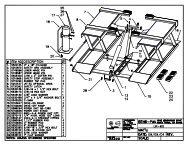
D0348-1 0374-1 1 MANDRINO SHAFT ASSEMBLY<br />
MOTORE+DATORE DI FASE+<br />
MOTOR+POSITION PICK-UP+<br />
D0199-2 0248-2 2<br />
TRASDUTTORI PIEZO<br />
PIEZO TRANSDUCER<br />
D495-4 495-4 4 BASAMENTO (1) CASING (1)<br />
D0440-5 495-5 5 BASAMENTO (2) CASING (2)<br />
D0440-6-CM 0215-6 6-CM CALIBRO DISTANZA (MANUALE) DISTANCE GAUGE (MANUAL)<br />
D0440-7 0440-7 7 POTENZA POWER UNIT<br />
D0440-8 0440-8 8 PROTEZIONE RUOTA WHEEL GUARD<br />
* Particolari reperibili in commercio * Standard hardware part
D0348-1<br />
1<br />
1 2 3 4 5 6 7 6<br />
8 9 6 7 10 11 12<br />
22<br />
21<br />
20<br />
19 18 17 16 15 14 13<br />
N. CODE DATA N. CODE DATA N. CODE DATA<br />
1 311225120 *<br />
11 04FM40630<br />
21 325046008 *<br />
2 325046010 *<br />
12 42FM41391 Ø 40 22 312120093 *<br />
3 326035011 *<br />
13 114008002 *<br />
4 42FM49794<br />
14 312120137 *<br />
5 04FM38621<br />
15 325047011 *<br />
6 341000025 *<br />
16 42FM51744 Ø 40 L = 205<br />
7 020600503 *<br />
17 344200118 *<br />
8 42FM60997<br />
18 42FP41056<br />
9 040010101<br />
19 181198630<br />
10 342000047 *<br />
20 326035009 *<br />
0374-1
D0199-2<br />
2<br />
12<br />
1<br />
5 6 7<br />
4<br />
3<br />
2<br />
8<br />
9<br />
10<br />
13<br />
14 15 17 16<br />
19<br />
31<br />
32<br />
30<br />
21<br />
20<br />
23<br />
24<br />
F<br />
G<br />
27<br />
20<br />
21<br />
26<br />
E<br />
D<br />
20<br />
21<br />
20<br />
22<br />
25<br />
24<br />
23<br />
20<br />
21<br />
D=WHITE<br />
E=YELLOW<br />
F=YELLOW<br />
G=BLUE<br />
N. CODE DATA N. CODE DATA N. CODE DATA<br />
1 86SD40731<br />
11 325046005 *<br />
19 080077004<br />
2 420610639<br />
12 50FG54366 230V/50-60 Hz 20 325035010 *<br />
3 42SD36228<br />
12 50FG54283 115V/50-60 Hz 21 321212010 *<br />
4 314231018 *<br />
13 348009014 *<br />
22 940701232<br />
5 67M38954C<br />
14 07FG41057 230V/50-60 Hz 23 345122515<br />
6 325035003 *<br />
14 07FG39089 115V/50-60 Hz (Usa) 24 326035011 *<br />
7 321232003 *<br />
15 326035004 *<br />
25 105110165<br />
8 311220072 *<br />
16 312120035 *<br />
26 105114744<br />
9 325046006 *<br />
17 325046004 *<br />
27 940701233<br />
10 325035006 *<br />
18 325035005 *<br />
28 312120054 *<br />
0248-2
D495-4<br />
4<br />
2 1<br />
9<br />
7<br />
8<br />
10<br />
3<br />
4<br />
5<br />
6<br />
N. CODE DATA N. CODE DATA N. CODE DATA<br />
1 14FB67430<br />
2 325035006 *<br />
3 325046006 *<br />
4 312120072 *<br />
5 42FB59113<br />
6 42BV53654<br />
7 42FB70336 Option<br />
8 200000016 *<br />
9 317220072 *<br />
10 310230616 *<br />
495-4
D0440-5<br />
5<br />
9<br />
7<br />
6<br />
5<br />
1<br />
4<br />
2<br />
10<br />
3<br />
6 8<br />
N. CODE DATA N. CODE DATA N. CODE DATA<br />
1 86PR69337<br />
2 321232003 *<br />
3 86SC69336<br />
4 527034980 *<br />
5 42PR54342<br />
6 315231015 *<br />
7 05PR55202<br />
8 329007663 *<br />
9 329004434 *<br />
10 681002000 *<br />
495-5
D0440-6-CM<br />
6-CM<br />
10<br />
11<br />
3<br />
2 5<br />
8<br />
9<br />
6<br />
4<br />
7<br />
1<br />
N. CODE DATA N. CODE DATA N. CODE DATA<br />
1 181206560<br />
11 315231034 *<br />
2 42FC40572<br />
3 335310040 *<br />
4 42FC40571<br />
5 040142902<br />
6 217019284<br />
7 217019283<br />
8 21FC47315<br />
9 312120071 *<br />
10 344100300 *<br />
0215-6
D0440-7<br />
7<br />
12 13 8 9 10 4 5 6<br />
3<br />
7<br />
1<br />
2<br />
11<br />
N. CODE DATA N. CODE DATA N. CODE DATA<br />
1 511242101<br />
9 317232034 *<br />
2 420419574<br />
10 611000150 15VA (230V)<br />
3 86SZ54503 230V 10 611000151 15VA (115V)<br />
3 86SZ54504 115V 11 526003246 *<br />
4 42SZ57702<br />
12 321232006 *<br />
5 527006175 *<br />
13 325047006 *<br />
6 67M53798A<br />
7 568001058 10MF (230V)<br />
7 568003558 35MF (115V)<br />
8 325035004 *<br />
0440-7
D0440-8<br />
8<br />
14<br />
1 2 3<br />
6<br />
11<br />
9<br />
12<br />
7<br />
16 15<br />
10 13<br />
3<br />
14<br />
5 8 4<br />
N. CODE DATA N. CODE DATA N. CODE DATA<br />
1 319216068 *<br />
11 213011873 *<br />
2 42FW32989<br />
12 325035004 *<br />
3 217019275<br />
13 523031916 *<br />
4 311220094 *<br />
14 213000351 without wheel only<br />
5 325035008 *<br />
15 86SB55636<br />
6 14FW54110<br />
16 517141308<br />
7 42FW54207<br />
8 212000351<br />
9 314231033 *<br />
10 42FW54204<br />
0440-8