First steps in hydrogen production from wind energy in Greece
First steps in hydrogen production from wind energy in Greece
First steps in hydrogen production from wind energy in Greece

You also want an ePaper? Increase the reach of your titles
YUMPU automatically turns print PDFs into web optimized ePapers that Google loves.
21, rue d'Artois, F-75008 Paris<br />
http://www.cigre.org<br />
D1-102<br />
Session 2004<br />
© CIGRÉ<br />
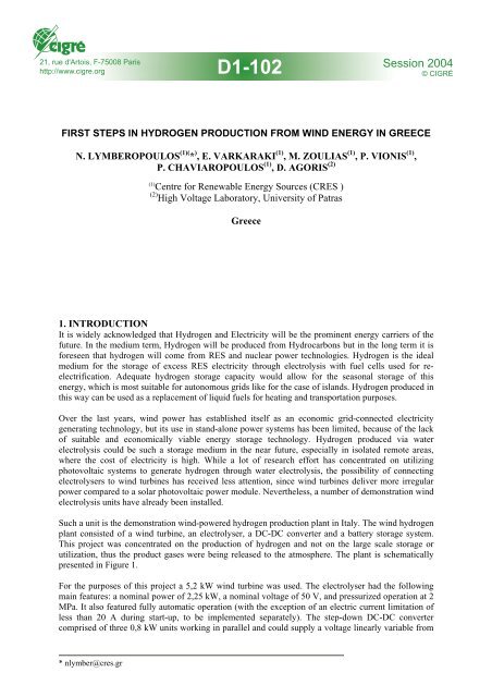
FIRST STEPS IN HYDROGEN PRODUCTION FROM WIND ENERGY IN GREECE<br />
N. LYMBEROPOULOS (1)( * ) , E. VARKARAKI (1) , M. ZOULIAS (1) , P. VIONIS (1) ,<br />
P. CHAVIAROPOULOS (1) , D. AGORIS (2)<br />
(1)<br />
Centre for Renewable Energy Sources (CRES )<br />
(2) High Voltage Laboratory, University of Patras<br />
<strong>Greece</strong><br />
1. INTRODUCTION<br />
It is widely acknowledged that Hydrogen and Electricity will be the prom<strong>in</strong>ent <strong>energy</strong> carriers of the<br />
future. In the medium term, Hydrogen will be produced <strong>from</strong> Hydrocarbons but <strong>in</strong> the long term it is<br />
foreseen that <strong>hydrogen</strong> will come <strong>from</strong> RES and nuclear power technologies. Hydrogen is the ideal<br />
medium for the storage of excess RES electricity through electrolysis with fuel cells used for reelectrification.<br />
Adequate <strong>hydrogen</strong> storage capacity would allow for the seasonal storage of this<br />
<strong>energy</strong>, which is most suitable for autonomous grids like for the case of islands. Hydrogen produced <strong>in</strong><br />
this way can be used as a replacement of liquid fuels for heat<strong>in</strong>g and transportation purposes.<br />
Over the last years, w<strong>in</strong>d power has established itself as an economic grid-connected electricity<br />
generat<strong>in</strong>g technology, but its use <strong>in</strong> stand-alone power systems has been limited, because of the lack<br />
of suitable and economically viable <strong>energy</strong> storage technology. Hydrogen produced via water<br />
electrolysis could be such a storage medium <strong>in</strong> the near future, especially <strong>in</strong> isolated remote areas,<br />
where the cost of electricity is high. While a lot of research effort has concentrated on utiliz<strong>in</strong>g<br />
photovoltaic systems to generate <strong>hydrogen</strong> through water electrolysis, the possibility of connect<strong>in</strong>g<br />
electrolysers to w<strong>in</strong>d turb<strong>in</strong>es has received less attention, s<strong>in</strong>ce w<strong>in</strong>d turb<strong>in</strong>es deliver more irregular<br />
power compared to a solar photovoltaic power module. Nevertheless, a number of demonstration w<strong>in</strong>d<br />
electrolysis units have already been <strong>in</strong>stalled.<br />
Such a unit is the demonstration w<strong>in</strong>d-powered <strong>hydrogen</strong> <strong>production</strong> plant <strong>in</strong> Italy. The w<strong>in</strong>d <strong>hydrogen</strong><br />
plant consisted of a w<strong>in</strong>d turb<strong>in</strong>e, an electrolyser, a DC-DC converter and a battery storage system.<br />
This project was concentrated on the <strong>production</strong> of <strong>hydrogen</strong> and not on the large scale storage or<br />
utilization, thus the product gases were be<strong>in</strong>g released to the atmosphere. The plant is schematically<br />
presented <strong>in</strong> Figure 1.<br />
For the purposes of this project a 5,2 kW w<strong>in</strong>d turb<strong>in</strong>e was used. The electrolyser had the follow<strong>in</strong>g<br />
ma<strong>in</strong> features: a nom<strong>in</strong>al power of 2,25 kW, a nom<strong>in</strong>al voltage of 50 V, and pressurized operation at 2<br />
MPa. It also featured fully automatic operation (with the exception of an electric current limitation of<br />
less than 20 A dur<strong>in</strong>g start-up, to be implemented separately). The step-down DC-DC converter<br />
comprised of three 0,8 kW units work<strong>in</strong>g <strong>in</strong> parallel and could supply a voltage l<strong>in</strong>early variable <strong>from</strong><br />
* nlymber@cres.gr
7 to 50 V, which was controlled by a 0-10 V DC signal. The battery storage unit comprised 54 seriesconnected<br />
lead-acid cells with a nom<strong>in</strong>al voltage of 2 V each and a nom<strong>in</strong>al capacity of 330 Ah, for a<br />
total nom<strong>in</strong>al capacity of 35,6 kWh. It must be noted that the full extent on this large capacity was<br />
probably not completely available, due to battery ag<strong>in</strong>g.<br />
Dur<strong>in</strong>g the w<strong>in</strong>d <strong>hydrogen</strong> plant operation, specific problems were observed. Regard<strong>in</strong>g the<br />
electrolysis unit, most of the problems were due to high impurity levels of <strong>hydrogen</strong> <strong>in</strong> oxygen dur<strong>in</strong>g<br />
operation at low current levels and high impurity levels of oxygen <strong>in</strong> <strong>hydrogen</strong> after some hours of<br />
stand-by operation, both conditions lead to alarms and automatic plant shutdown. On the w<strong>in</strong>d turb<strong>in</strong>e<br />
side, it has been proved that a variable w<strong>in</strong>d speed turb<strong>in</strong>e, equipped with a synchronous generator, the<br />
decoupl<strong>in</strong>g provided by the AC-DC(/AC) <strong>in</strong>terface removed the resonant mode of the direct grid<br />
coupl<strong>in</strong>g and the power fluctuations due to tower shadow and rotational sampl<strong>in</strong>g of w<strong>in</strong>d shear over<br />
the turb<strong>in</strong>e rotor. The power smooth<strong>in</strong>g was typically effective on time scales of up to 20 seconds [1,<br />
2].<br />
Figure 1. Basic scheme for demonstration w<strong>in</strong>d-powered <strong>hydrogen</strong> generation plant, [2].<br />
Another w<strong>in</strong>d-<strong>hydrogen</strong> system has been <strong>in</strong>stalled <strong>in</strong> Canada. This system really operated <strong>in</strong> standalone<br />
mode [3]. The system consisted of the follow<strong>in</strong>g components:<br />
• A w<strong>in</strong>d turb<strong>in</strong>e that was able to deliver a maximum output power of 10 kW. The w<strong>in</strong>d turb<strong>in</strong>e was<br />
coupled to a PV array with a maximum output power of 1 kW. The voltage produced by these<br />
sources was regulated and converted to a 48 V on a DC bus. A set of batteries connected <strong>in</strong> a<br />
series/parallel configuration acted as a buffer between the load and the power sources.<br />
• A 5 kW electrolyser which was able to deliver up to 1 m 3 /h of <strong>hydrogen</strong>, subsequently purified,<br />
dried and compressed at 0,7 MPa (a).<br />
• The <strong>hydrogen</strong> was further compressed to 1 MPa, and directed to a storage tank with a capacity of<br />
3,8 m 3 (water capacity).<br />
• A 5 kW-24 V DC proton exchange membrane fuel cell stack, with an effective voltage output of 19-<br />
35V.<br />
• 48 V deep-discharge batteries for voltage stabilization, of 42.24 kWh storage capacity<br />
• A 12 kW water cooler.<br />
• A DC bus controller <strong>in</strong>clud<strong>in</strong>g the batteries for <strong>energy</strong> transfer.<br />
• A DC-AC <strong>in</strong>verter, which was able to deliver a constant 60 Hz 115 V output to the load.<br />
Accord<strong>in</strong>g to Agbossou et al [3], the electrolyser efficiencies without compressor are 65% at ambient<br />
temperature around 23 o C and 71% at 55 o C. There is a decrease of 5% <strong>in</strong> these efficiencies when<br />
<strong>hydrogen</strong> is compressed. Assess<strong>in</strong>g the experimental results, it was estimated that for an average w<strong>in</strong>d<br />
2
speed at the test site of 6 m/s which translates <strong>in</strong> an average w<strong>in</strong>d turb<strong>in</strong>e power of approximately 2<br />
kW, the <strong>hydrogen</strong> <strong>production</strong> rate was about 0,4 Nm 3 /h.<br />
The load-level<strong>in</strong>g electrical system is composed of the 5 kW fuel cell system connected to the DC bus,<br />
through a regulated DC-DC converter (24/48 V). The specific fuel cell consists of a total of 35 cells<br />
connected <strong>in</strong> series. Each cell has a surface area of 225 cm 2 . The reactant gases (<strong>hydrogen</strong> and air) are<br />
humidified with<strong>in</strong> the stack. The <strong>hydrogen</strong> is recirculated at the anode and the air is directed to the<br />
cathode. The DC-DC converter has an efficiency that exceeds 95%. The efficiency of the fuel cell<br />
system <strong>in</strong> convert<strong>in</strong>g <strong>hydrogen</strong> <strong>in</strong>to electricity is approximately 45% when deliver<strong>in</strong>g a power of 4<br />
kW. Therefore, the overall efficiency of the load-level<strong>in</strong>g electrical system is about 42%. This system<br />
is proposed for provid<strong>in</strong>g stabilized electrical power for communication stations.<br />
Another <strong>in</strong>terest<strong>in</strong>g w<strong>in</strong>d-electrolysis system has been studied <strong>in</strong> Germany [4]. The w<strong>in</strong>d turb<strong>in</strong>e is a<br />
two-speed asynchronous generator with a nom<strong>in</strong>al power output of 100 kW. The alkal<strong>in</strong>e electrolyser<br />
delivers <strong>hydrogen</strong> at up to 2,5 MPa and a <strong>hydrogen</strong> compressor can be used to <strong>in</strong>crease the pressure up<br />
to 30 MPa. Upon exit<strong>in</strong>g the electrolyser, the <strong>hydrogen</strong> is purified and dried. The <strong>hydrogen</strong> storage<br />
tank has a geometrical volume of 8 m 3 and conta<strong>in</strong>s 200 Nm 3 H 2 at 2,5 MPa. It is filled <strong>in</strong> 50 hours at<br />
nom<strong>in</strong>al electrolyser capacity (4 Nm 3 /h H 2 ).<br />
For steady state operation, the nom<strong>in</strong>al current is set to 120 A. Initially, when the system is at ambient<br />
temperature and pressure, the control system applies a current limitation until the pressure <strong>in</strong> the<br />
system atta<strong>in</strong>s 1,3 MPa. At this po<strong>in</strong>t, the <strong>hydrogen</strong> delivery can start. Upon reach<strong>in</strong>g the 1,3 MPa, the<br />
<strong>in</strong>itial current limitation is switched off and the actual current is only limited by the temperature. It<br />
takes circa 45 m<strong>in</strong>utes for the electrolyser to achieve the operat<strong>in</strong>g temperature of 75ºC and therefore<br />
the nom<strong>in</strong>al current of 120 A. The reported efficiency of the electrolyser is very low (approximately<br />
56%) [4]. The electrolyser has also been tested under a controlled operat<strong>in</strong>g regime, probably through<br />
a simulator of variable power <strong>in</strong>put. Accord<strong>in</strong>g to the related publications [4,5], there has been no<br />
direct connection between the w<strong>in</strong>d turb<strong>in</strong>e and the electrolyser.<br />
The objective of this paper is to give a brief<strong>in</strong>g about the first <strong>steps</strong> <strong>in</strong> Hydrogen <strong>production</strong> <strong>from</strong> w<strong>in</strong>d<br />
<strong>energy</strong> <strong>in</strong> <strong>Greece</strong>. The ma<strong>in</strong> features of a major <strong>in</strong>stallation related to <strong>hydrogen</strong> <strong>production</strong> <strong>from</strong> w<strong>in</strong>d<br />
<strong>energy</strong> that is be<strong>in</strong>g erected <strong>in</strong> <strong>Greece</strong> by CRES, the Greek National co-ord<strong>in</strong>ation centre for<br />
Renewables and Rational Use of Energy will be described with reference to the previously mentioned<br />
similar <strong>in</strong>stallations. This, new <strong>in</strong>stallation is related to the <strong>production</strong> of “green” Hydrogen <strong>from</strong> w<strong>in</strong>d<br />
<strong>energy</strong>, as a potential alternative product to electricity and is be<strong>in</strong>g developed <strong>in</strong> the context of an EC<br />
co-funded project. Potential applications of similar w<strong>in</strong>d-<strong>hydrogen</strong> systems on Greek islands are also<br />
discussed.<br />
2. SYSTEM OUTLINE<br />
The w<strong>in</strong>d-<strong>hydrogen</strong> system under development at a w<strong>in</strong>d park <strong>in</strong> Lavrion, <strong>Greece</strong> consists of a<br />
pressurised electrolyser with a 25 kW / 5 Nm 3 /hr <strong>production</strong> capacity operat<strong>in</strong>g at 1,5 MPa that is<br />
connected to a commercial variable speed pitch-regulated w<strong>in</strong>d turb<strong>in</strong>e power<strong>in</strong>g the whole plant.<br />
Through appropriate control strategies, major power fluctuations are fed to the electrolyser and the<br />
rema<strong>in</strong><strong>in</strong>g “more uniform” <strong>energy</strong> is fed to the electricity grid. Hydrogen is stored <strong>in</strong> a metal hydride<br />
tank (50 Nm 3 capacity) and is compressed <strong>in</strong> cyl<strong>in</strong>ders at 20 MPa pressure. The produced high purity<br />
(99.999%) Hydrogen will be fed to the exist<strong>in</strong>g Greek Hydrogen market that is non-<strong>energy</strong> related, as<br />
a way to <strong>in</strong>vestigate alternative commercial paths for w<strong>in</strong>d park developers. The w<strong>in</strong>d turb<strong>in</strong>e used is<br />
grid connected.<br />
3. SYSTEM DESIGN<br />
The water electrolysis unit is connected to the 400 V l<strong>in</strong>e of a 500 kW gearless, synchronous,<br />
multipole w<strong>in</strong>d turb<strong>in</strong>e. The <strong>hydrogen</strong> produced by electrolysis is purified flows <strong>in</strong>to a small,<br />
conventional buffer tank. From the buffer tank, there are two different pathways available for the<br />
<strong>hydrogen</strong>. One is to flow <strong>in</strong>to a metal hydride tank of 50 Nm 3 H 2 capacity and the other is to flow to a<br />
compressor and subsequently to a fill<strong>in</strong>g station, to fill <strong>hydrogen</strong> cyl<strong>in</strong>ders at 20-22 MPa. When the<br />
3
electrolyser is not <strong>in</strong> operation, the <strong>hydrogen</strong> stored <strong>in</strong> the metal hydride tank can be used to supply the<br />
compressor and fill the cyl<strong>in</strong>ders.<br />
The materials of construction for the pip<strong>in</strong>g and all the vessels must not be subject to <strong>hydrogen</strong><br />
embrittlement. The materials suitable for <strong>hydrogen</strong> service are sta<strong>in</strong>less steel, carbon steel, alum<strong>in</strong>um<br />
and copper. A process flowsheet of the plant is presented <strong>in</strong> Figure 2.<br />
O2 vent<br />
10<br />
H2 vent<br />
11<br />
Hydrogen<br />
Cooler<br />
HC 12<br />
4<br />
CRES<br />
FIT<br />
CWout<br />
Oxygen<br />
OF<br />
Filter<br />
Hydrogen<br />
Filter HF<br />
DO<br />
deoxo<br />
dryer<br />
HD<br />
CV3<br />
MHT<br />
Metal Hydride<br />
Tank<br />
PC<br />
TC<br />
CWout<br />
OS<br />
Oxygen<br />
Separator<br />
10 11<br />
LC<br />
HS<br />
Hydrogen<br />
Separator<br />
LC<br />
CW<strong>in</strong><br />
3<br />
AI<br />
CV1<br />
CV2<br />
TC<br />
CW<strong>in</strong><br />
5<br />
Electrical<br />
Heater<br />
CW<strong>in</strong><br />
6<br />
H2 vent<br />
12<br />
PCV<br />
PC TC 12<br />
PCV<br />
CV4<br />
Electrolysis<br />
Stack<br />
TC<br />
Conventional<br />
H2 Buffer tank<br />
Legend<br />
CW: Cool<strong>in</strong>g Water<br />
DW: Dem<strong>in</strong>eralised Water<br />
PI: Pressure Indicator<br />
PC: Pressure Controller<br />
TI: Temperature Indicator<br />
TC: Temperature Controller<br />
AI: Analysis Indicator<br />
CV: Control Valve<br />
Battery Limits<br />
1 : DW <strong>in</strong>let<br />
10 : Oxygen vent<br />
2 : Air <strong>in</strong>let<br />
11 : Hydrogen vent<br />
3 - 7 : CW <strong>in</strong>lets<br />
12 : Hydrogen vent<br />
DWP<br />
Water Tank<br />
Water <strong>in</strong>let<br />
Water dem<strong>in</strong>eraliser<br />
CW <strong>in</strong>, T, P, m3/h<br />
3 4 5 6 7<br />
HS<br />
HC MHT MHT CC<br />
OS<br />
CW out, T<br />
CV5<br />
ROKAS<br />
Compressor<br />
Compressor<br />
Cooler<br />
7<br />
CC<br />
Cyl<strong>in</strong>ders' Fill<strong>in</strong>g Station<br />
TC<br />
Figure 2. Prelim<strong>in</strong>ary process flowsheet of the <strong>hydrogen</strong> plant at the w<strong>in</strong>d-park of CRES<br />
4. COMPONENTS OF THE HYDROGEN PRODUCTION PLANT<br />
The <strong>hydrogen</strong> <strong>production</strong> plant comprises a water electrolyser with a <strong>hydrogen</strong> purification unit, a<br />
compressed <strong>hydrogen</strong> buffer tank, a metal hydride tank, a <strong>hydrogen</strong> compressor, a cyl<strong>in</strong>der fill<strong>in</strong>g<br />
station and a control and power condition<strong>in</strong>g unit. The operational characteristics of each component<br />
are described below.<br />
4.1. Water electrolyser<br />
The water electrolyser is a key element for the w<strong>in</strong>d-<strong>hydrogen</strong> plant, because its technical<br />
characteristics and delivery conditions have an important impact on the follow<strong>in</strong>g subsystems. Two<br />
different electrolyser technologies have been <strong>in</strong>vestigated as possible options with<strong>in</strong> the available<br />
budget. The first option is to <strong>in</strong>stall a conventional alkal<strong>in</strong>e electrolyser of 10 Nm 3 /h H 2 capacity,<br />
consum<strong>in</strong>g approximately 55 kW of electrical power and deliver<strong>in</strong>g <strong>hydrogen</strong> at 0,5 MPa(g) pressure.<br />
The second option is to <strong>in</strong>stall an advanced alkal<strong>in</strong>e electrolyser of 5 Nm 3 /h H 2 capacity, consum<strong>in</strong>g<br />
approximately 25 kW of power and deliver<strong>in</strong>g <strong>hydrogen</strong> at m<strong>in</strong>imum 1 MPa(g) pressure. In both<br />
cases, the oxygen produced will be vented, because no use of oxygen has been foreseen.<br />
The detailed analysis of these two options showed that the choice of an advanced alkal<strong>in</strong>e electrolyser<br />
presents several advantages. Advanced, pressurized electrolysers are safer, more reliable and more<br />
efficient than conventional electrolysers. In addition, the delivery of <strong>hydrogen</strong> at higher pressures (1-2<br />
MPa(g)) adds a precious versatility to the global plant.<br />
Conventional electrolysers are cheaper, so they offer the advantage of <strong>in</strong>stall<strong>in</strong>g a unit of higher<br />
capacity for the same budget, but they have never been tested <strong>in</strong> <strong>in</strong>termittent operation, and they are<br />
not designed for part load operation, as advanced electrolysers do.<br />
4
The purity of the <strong>hydrogen</strong> com<strong>in</strong>g out of an alkal<strong>in</strong>e electrolyser varies <strong>from</strong> 99.5% for a<br />
conventional one to 99.9% for advanced ones. This purity is generally atta<strong>in</strong>ed at full load operation<br />
and decreases upon part load operation. The electrolytically produced <strong>hydrogen</strong> conta<strong>in</strong>s small<br />
quantities of oxygen, which is dissolved <strong>in</strong> the electrolyte at the operat<strong>in</strong>g temperature and diffuses<br />
<strong>from</strong> the oxygen to the <strong>hydrogen</strong> compartment. In addition, the <strong>hydrogen</strong> flow is saturated with water<br />
vapour at the delivery pressure and temperature.<br />
The <strong>hydrogen</strong> com<strong>in</strong>g out of the electrolyser must be purified to circa 99.999% vol., because such a<br />
high purity is generally required for the metal hydride tanks. Hydrogen conta<strong>in</strong><strong>in</strong>g large quantities of<br />
water vapour may also cause water condensation problems <strong>in</strong>side the <strong>hydrogen</strong> compressor. Thus, a<br />
<strong>hydrogen</strong> purification unit must be added to the system.<br />
4.2. Hydrogen buffer tank<br />
A small <strong>hydrogen</strong> buffer tank is necessary after the electrolyser and purification section, <strong>in</strong> order for<br />
the plant to operate smoothly. The role of the buffer is to absorb the eventual pressure variations at the<br />
outlet of the electrolysis and purification section. In addition, if the electrolyser is tripped out for any<br />
reason (absence of w<strong>in</strong>d, emergency shut-down), the buffer tank gives to the system more time for a<br />
regular shutdown.<br />
4.3. Metal hydride tank<br />
Hydrogen will be ma<strong>in</strong>ly stored <strong>in</strong> a metal hydride tank. Some AB 5 -type materials, with the<br />
compositions La 1-x R x Ni 5-y M y , where R= Nd, M=Co, Fe, Cu and x=0-0.2, y=0-1 and the AB 2 -type<br />
materials, with the compositions Zr 0.8 Ti 0.2 (Ni x Mn 0.9-x V 0.1 ) 2 , x=0.4, 0.5, 0.6, 0.7, 0.8, have been<br />
homogenised and characterised <strong>in</strong> terms of phases present and <strong>hydrogen</strong> absorption. New alloys with<br />
compositions LaNi 5-x Al x , where x=0-0.25 have also been prepared for study<strong>in</strong>g. The goal of achiev<strong>in</strong>g<br />
<strong>hydrogen</strong> capacities of more that 0,1 m 3 /kg of material has been achieved easily. Most of the materials<br />
tested show a capacity of more that 0,150 m 3 /kg at room temperature and low pressures (
The compressor module is basically composed of 6 major pieces or groups of equipment: the<br />
compressor, the motor, the term<strong>in</strong>al box and panel, the control cab<strong>in</strong>et, the sensors and controls and<br />
the aftercooler. Interstage cool<strong>in</strong>g with a condensate separator after the cool<strong>in</strong>g stage may also be<br />
required, but will be decided later dur<strong>in</strong>g the design of the compressor. Purg<strong>in</strong>g with an <strong>in</strong>ert gas (i.e.<br />
nitrogen) is generally foreseen and strongly recommended. A frequency controlled motor may be<br />
used, <strong>in</strong> order to be able to vary the <strong>in</strong>put power to the compressor. The operation with a frequency<br />
controller is generally limited to the range 50-100% of capacity.<br />
Follow<strong>in</strong>g the prelim<strong>in</strong>ary design of the plant, the <strong>hydrogen</strong> compressor should have a capacity of 5-<br />
10 Nm 3 /h, for a suction pressure of 0,3-0,7 MPa and a delivery pressure of 22 MPa. The f<strong>in</strong>al pressure<br />
<strong>in</strong> the cyl<strong>in</strong>ders would be 20 MPa at the ambient temperature of 25ºC, assum<strong>in</strong>g that the temperature<br />
of the <strong>hydrogen</strong> compressed at 22 MPa at the outlet of the aftercooler would be circa 60ºC.<br />
4.5 Cyl<strong>in</strong>der fill<strong>in</strong>g station<br />
Cyl<strong>in</strong>ders represent a convenient supply source for applications with gas requirements up to 5000 m 3<br />
per month. The cyl<strong>in</strong>ders may be made of alum<strong>in</strong>um, steel, light alloy or composite materials. They<br />
can be supplied <strong>in</strong>dividually or <strong>in</strong> sets of 9 or 18 bundled together and emptied as a unit.<br />
The fill<strong>in</strong>g station that will be constructed at the w<strong>in</strong>d park of CRES will probably be designed so as to<br />
be able to fill two or three 9-cyl<strong>in</strong>der bundles simultaneously. Assum<strong>in</strong>g a cyl<strong>in</strong>der capacity of 0,050<br />
m 3 , the storage volume at the fill<strong>in</strong>g station with two bundles can be estimated around 0,900 m 3 , which<br />
corresponds to a capacity of circa 165 Nm 3 H 2 at 20 MPa and 25ºC. The fill<strong>in</strong>g station should be<br />
placed at least 6-10 metres away <strong>from</strong> the compressor and preferably separated by a short wall.<br />
4.6. Control and Power Condition<strong>in</strong>g unit<br />
The Power Condition<strong>in</strong>g Unit (PCU) is ma<strong>in</strong>ly a power distribution board, tak<strong>in</strong>g power <strong>from</strong> the w<strong>in</strong>d<br />
turb<strong>in</strong>e and distribut<strong>in</strong>g to the various users. It is schematically presented <strong>in</strong> Figure 3, with the<br />
potential electricity users. The power characteristics of the ma<strong>in</strong> electricity users, namely the<br />
electrolyser, compressor, electrical heater for the metal hydride tank, water refrigerat<strong>in</strong>g and pump<strong>in</strong>g<br />
unit, are 400 V, 50 Hz, 3 phase. The power characteristics of the Central Control Unit have not yet<br />
been def<strong>in</strong>ed.<br />
When the plant is operat<strong>in</strong>g, the PCU must supply the necessary power to the appropriate users.<br />
Accord<strong>in</strong>g to the possible modes of operation of the plant, not all the electricity users may operate<br />
simultaneously. The simultaneous operation of the electrolyser, compressor and metal hydride tank<br />
heater is excluded. However, the Central Control and Cool<strong>in</strong>g Water units will always need some<br />
power when the system is operat<strong>in</strong>g. The maximum total power consumption of the plant <strong>in</strong> operation<br />
is approximately 40 kW.<br />
W<strong>in</strong>d<br />
Generator<br />
400 V<br />
3 ph.<br />
50 Hz<br />
20 kV Grid<br />
ca. 1 kW<br />
3.75 - 25 kW<br />
Central<br />
Control<br />
Unit<br />
Electrolyser<br />
Power Supply<br />
Cab<strong>in</strong>et<br />
ca. 5 kW<br />
Compressor<br />
POWER<br />
CONDITIONING<br />
UNIT<br />
(POWER<br />
DISTRIBUTION<br />
BOARD)<br />
0 - 2 kW<br />
0 - 8 kW<br />
MHT heater<br />
Cool<strong>in</strong>g Water<br />
Refrigerat<strong>in</strong>g<br />
& Pump<strong>in</strong>g Unit<br />
Figure 3. A simplified scheme of the Power Condition<strong>in</strong>g Unit<br />
6
The ma<strong>in</strong> characteristics of the different electricity users are presented <strong>in</strong> Table I, and some more<br />
detailed explanations are given hereafter.<br />
Item<br />
1. Electrolyser<br />
Power<br />
Supply<br />
Cab<strong>in</strong>et<br />
2. Compressor<br />
3. MHT heater<br />
4. Cool<strong>in</strong>g<br />
water<br />
refrigerat<strong>in</strong>g &<br />
pump<strong>in</strong>g unit<br />
5. Central<br />
Control Unit<br />
Table I. Ma<strong>in</strong> power characteristics of the different plant units<br />
Ma<strong>in</strong> Power Characteristics<br />
The electrolyser cab<strong>in</strong>et <strong>in</strong>cludes the AC/DC converter to supply the electrolysis<br />
stack with the appropriate DC power. The operat<strong>in</strong>g range of the electrolyser is<br />
3.75 – 25 kW, correspond<strong>in</strong>g to a <strong>hydrogen</strong> <strong>production</strong> of 0.75 – 5 Nm 3 /h. A fullrange<br />
power variation is possible with<strong>in</strong> 1 second.<br />
The correspond<strong>in</strong>g power necessary for cool<strong>in</strong>g the water and pump<strong>in</strong>g it <strong>in</strong>to the<br />
system varies <strong>in</strong> the range 0 – 4 kW, but not <strong>in</strong> a l<strong>in</strong>ear manner.<br />
The power <strong>in</strong>put to the compressor will be circa 5 – 7.5 kW, to be precisely<br />
def<strong>in</strong>ed by the manufacturer (not chosen yet). It must rema<strong>in</strong> rather constant, but<br />
an eventual variation range must be checked with the manufacturer.<br />
At full power, the compressor should need approximately 4 kW for cool<strong>in</strong>g water<br />
and recirculation pump<strong>in</strong>g.<br />
Dur<strong>in</strong>g <strong>hydrogen</strong> delivery, the Metal Hydride Tank must be heated. At nom<strong>in</strong>al<br />
discharge rate, i.e. 5 Nm 3 /h H 2 , approximately 2 kW power are needed. Dur<strong>in</strong>g<br />
<strong>hydrogen</strong> absorption, the Metal Hydride Tank may need cool<strong>in</strong>g, with<br />
approximately 2 kW cool<strong>in</strong>g required at the absorption rate of 5 Nm 3 /h. The<br />
heat<strong>in</strong>g and cool<strong>in</strong>g power may vary as a function of the absorption and desorption<br />
pressure and temperature.<br />
Dur<strong>in</strong>g normal operation, the maximum quantity of cool<strong>in</strong>g water may be needed<br />
dur<strong>in</strong>g the simultaneous operation of the electrolyser and compressor. It<br />
corresponds to 8 kW cool<strong>in</strong>g <strong>energy</strong>. So, the <strong>energy</strong> for the refrigeration of the<br />
cool<strong>in</strong>g water will vary <strong>in</strong> the range 0 – 8 kW.<br />
The CCU needs some power, <strong>in</strong> order to receive signals, treat them and send other<br />
signals to the different control elements of the plant. The data monitor<strong>in</strong>g is also<br />
<strong>in</strong>cluded <strong>in</strong> the CCU. CCU power consumption is estimated around 1 kW.<br />
The PCU will be <strong>in</strong>stalled <strong>in</strong> a non hazardous zone of the plant. A m<strong>in</strong>imum distance of 5 meters is<br />
foreseen <strong>from</strong> the zones with possible presence of <strong>in</strong>flammable gases, accord<strong>in</strong>g to the available codes<br />
of practice.<br />
5. FUTURE APPLICATIONS FOR SIMILAR WIND-HYDROGEN SYSTEMS<br />
The concept of us<strong>in</strong>g <strong>hydrogen</strong> as a medium for the storage of excess w<strong>in</strong>d <strong>energy</strong> through water<br />
electrolysis with fuel cells used for re-electrification is considered ideal for most of the non<strong>in</strong>terconnected<br />
Greek islands. Adequate <strong>hydrogen</strong> storage capacity would allow for the seasonal<br />
storage of this <strong>energy</strong>, which is most suitable for autonomous grids like for the case of islands.<br />
Hydrogen produced <strong>in</strong> this way can be used as a replacement of liquid fuels for heat<strong>in</strong>g and<br />
transportation purposes. A pre-feasibility study related to the <strong>in</strong>troduction of a w<strong>in</strong>d-<strong>hydrogen</strong> <strong>energy</strong><br />
system <strong>in</strong> the island of Kythnos is briefly presented. It must be noted that the proposed system design<br />
and dimension<strong>in</strong>g was performed with the TRNSYS simulation tool where the HYDROGEMS library<br />
of modules has been <strong>in</strong>corporated [6].<br />
Kythnos island <strong>in</strong> <strong>Greece</strong> has a peak power demand of approximately 2.5 MW and is electrified<br />
ma<strong>in</strong>ly by diesel generators sets. A w<strong>in</strong>d turb<strong>in</strong>e with a nom<strong>in</strong>al power of 500 kW and a photovoltaic<br />
system of around 100 kW have also been <strong>in</strong>stalled on the island. The ma<strong>in</strong> problem related to the w<strong>in</strong>d<br />
7
turb<strong>in</strong>e operation is that it is currently connected and is shedd<strong>in</strong>g power to 500 kW of electrical<br />
resistances <strong>in</strong> order to ensure the stability of the autonomous electricity grid of Kythnos. The<br />
<strong>in</strong>troduction of a <strong>hydrogen</strong> system to the exist<strong>in</strong>g <strong>energy</strong> system of the island would significantly<br />
reduce the shedd<strong>in</strong>g of power to the electrical resistances and <strong>in</strong>crease the penetration of Renewable<br />
Energy Sources.<br />
The exist<strong>in</strong>g 500 kW w<strong>in</strong>d turb<strong>in</strong>e is proposed to be connected to a <strong>hydrogen</strong> <strong>production</strong>, storage and<br />
re-electrification plant. A 100 kW electrolyser operat<strong>in</strong>g at a pressure of 1,5 MPa connected to the<br />
w<strong>in</strong>d turb<strong>in</strong>e can be used for <strong>hydrogen</strong> <strong>production</strong>. Hydrogen storage <strong>in</strong> conventional pressure tanks<br />
able to store up to 4,800 Nm 3 of <strong>hydrogen</strong> is <strong>in</strong>dicated. PEM fuel cells (with a nom<strong>in</strong>al power of<br />
approximately 25 kW) should also be <strong>in</strong>stalled for re-electrification purposes. Hence, the electrolysis<br />
unit can be used rather than the electrical resistances as the load-levell<strong>in</strong>g device, by send<strong>in</strong>g to the<br />
electrolyser major power fluctuations (up to 120% of the nom<strong>in</strong>al capacity of the electrolyser, any<br />
excess <strong>energy</strong> to this would still go to the resistances). Stored <strong>energy</strong> <strong>in</strong> the form of <strong>hydrogen</strong> can be<br />
fed back to the grid through the fuel cells demonstrat<strong>in</strong>g that a RES <strong>in</strong>stallation that has been<br />
hybridised with <strong>hydrogen</strong> technologies can provide a m<strong>in</strong>imum guarantied level of power, equal to the<br />
nom<strong>in</strong>al capacity of the fuel cells. It is estimated that 120.000 kWh that would have otherwise been<br />
lost could be fed to the local grid per annum.<br />
W<strong>in</strong>d <strong>energy</strong> based systems that <strong>in</strong>corporate appropriate <strong>hydrogen</strong> storage and re-electrification<br />
technologies could thus be “promoted” <strong>from</strong> stochastic sources of electrical <strong>energy</strong> to dispatchable<br />
power plants.<br />
6. ACKNOWLEDGEMENTS<br />
The development of the described w<strong>in</strong>d-driven <strong>hydrogen</strong> plant <strong>in</strong> Lavrion, <strong>Greece</strong> is be<strong>in</strong>g co-funded<br />
by the EC <strong>in</strong> the context of the RES2H2 project (contract ENK5-CT-2001-00536). This project<br />
<strong>in</strong>volves 16 partners and two test sites, the second test site be<strong>in</strong>g <strong>in</strong> the Canary Islands, Spa<strong>in</strong>. A<br />
research centre <strong>from</strong> Cyprus and a w<strong>in</strong>d park developer <strong>from</strong> <strong>Greece</strong> are contribut<strong>in</strong>g with hardware <strong>in</strong><br />
the realisation of the Greek test site.<br />
7. REFERENCES<br />
1. T. Schucan, IEA Hydrogen Implement<strong>in</strong>g Agreement Task 11: Integrated systems-F<strong>in</strong>al Report of<br />
subtask A: Case studies of <strong>in</strong>tegrated <strong>hydrogen</strong> <strong>energy</strong> systems, 1998, p. 5-102, 117-145.<br />
2. A.G. Dutton, J.A.M. Bleijs, H. Dienhart, M. Falchetta, W. Hug, D. Prischich, and A.J. Rudell,<br />
Experience <strong>in</strong> the design, siz<strong>in</strong>g, economics, and implementation of autonomous w<strong>in</strong>d-powered<br />
<strong>hydrogen</strong> <strong>production</strong> systems (Int. J. Hydrogen Energy 25(2000) p.705-722).<br />
3. K. Agbossou , R. Chah<strong>in</strong>e, J. Hamel<strong>in</strong>, F. Laurencelle, A. Anouar, J-M. St-Arnaud, T.K. Bose,<br />
Renewable <strong>energy</strong> systems based on <strong>hydrogen</strong> for remote applications (Journal of Power Sources<br />
96(2001) p. 168-172).<br />
4. F. Menzl, M. Wenske, J. Lehmann, W<strong>in</strong>dmill-electrolyser-system for a <strong>hydrogen</strong> based <strong>energy</strong><br />
supply, <strong>in</strong> Wissenschaftliche Schriftenreihe Fachhochschule Stralsund, Nummer 2: Regenerative<br />
Energien, 2001.<br />
5. J. Lehmann, T. Luscht<strong>in</strong>etz, F. Menzl, The w<strong>in</strong>d-<strong>hydrogen</strong>-fuel cell cha<strong>in</strong> (14 th World Hydrogen<br />
Energy Conference, Montreal, Canada, June 9-13, 2002).<br />
6. Ø. Ulleberg, R. Glöckner, HYDROGEMS - Hydrogen Energy Models (14 th World Hydrogen<br />
Energy Conference, Montreal, Canada, June 9-13, 2002).<br />
8