First steps in hydrogen production from wind energy in Greece
First steps in hydrogen production from wind energy in Greece
First steps in hydrogen production from wind energy in Greece

Create successful ePaper yourself
Turn your PDF publications into a flip-book with our unique Google optimized e-Paper software.
The compressor module is basically composed of 6 major pieces or groups of equipment: the<br />
compressor, the motor, the term<strong>in</strong>al box and panel, the control cab<strong>in</strong>et, the sensors and controls and<br />
the aftercooler. Interstage cool<strong>in</strong>g with a condensate separator after the cool<strong>in</strong>g stage may also be<br />
required, but will be decided later dur<strong>in</strong>g the design of the compressor. Purg<strong>in</strong>g with an <strong>in</strong>ert gas (i.e.<br />
nitrogen) is generally foreseen and strongly recommended. A frequency controlled motor may be<br />
used, <strong>in</strong> order to be able to vary the <strong>in</strong>put power to the compressor. The operation with a frequency<br />
controller is generally limited to the range 50-100% of capacity.<br />
Follow<strong>in</strong>g the prelim<strong>in</strong>ary design of the plant, the <strong>hydrogen</strong> compressor should have a capacity of 5-<br />
10 Nm 3 /h, for a suction pressure of 0,3-0,7 MPa and a delivery pressure of 22 MPa. The f<strong>in</strong>al pressure<br />
<strong>in</strong> the cyl<strong>in</strong>ders would be 20 MPa at the ambient temperature of 25ºC, assum<strong>in</strong>g that the temperature<br />
of the <strong>hydrogen</strong> compressed at 22 MPa at the outlet of the aftercooler would be circa 60ºC.<br />
4.5 Cyl<strong>in</strong>der fill<strong>in</strong>g station<br />
Cyl<strong>in</strong>ders represent a convenient supply source for applications with gas requirements up to 5000 m 3<br />
per month. The cyl<strong>in</strong>ders may be made of alum<strong>in</strong>um, steel, light alloy or composite materials. They<br />
can be supplied <strong>in</strong>dividually or <strong>in</strong> sets of 9 or 18 bundled together and emptied as a unit.<br />
The fill<strong>in</strong>g station that will be constructed at the w<strong>in</strong>d park of CRES will probably be designed so as to<br />
be able to fill two or three 9-cyl<strong>in</strong>der bundles simultaneously. Assum<strong>in</strong>g a cyl<strong>in</strong>der capacity of 0,050<br />
m 3 , the storage volume at the fill<strong>in</strong>g station with two bundles can be estimated around 0,900 m 3 , which<br />
corresponds to a capacity of circa 165 Nm 3 H 2 at 20 MPa and 25ºC. The fill<strong>in</strong>g station should be<br />
placed at least 6-10 metres away <strong>from</strong> the compressor and preferably separated by a short wall.<br />
4.6. Control and Power Condition<strong>in</strong>g unit<br />
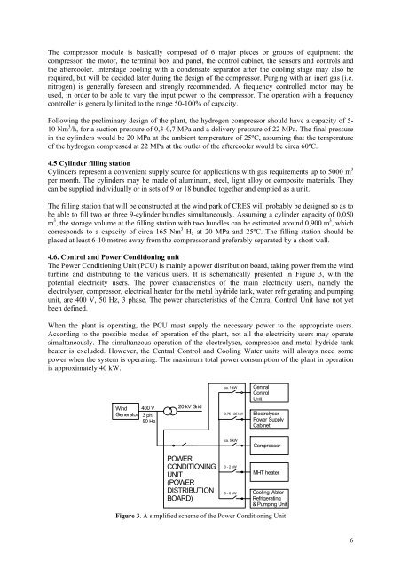
The Power Condition<strong>in</strong>g Unit (PCU) is ma<strong>in</strong>ly a power distribution board, tak<strong>in</strong>g power <strong>from</strong> the w<strong>in</strong>d<br />
turb<strong>in</strong>e and distribut<strong>in</strong>g to the various users. It is schematically presented <strong>in</strong> Figure 3, with the<br />
potential electricity users. The power characteristics of the ma<strong>in</strong> electricity users, namely the<br />
electrolyser, compressor, electrical heater for the metal hydride tank, water refrigerat<strong>in</strong>g and pump<strong>in</strong>g<br />
unit, are 400 V, 50 Hz, 3 phase. The power characteristics of the Central Control Unit have not yet<br />
been def<strong>in</strong>ed.<br />
When the plant is operat<strong>in</strong>g, the PCU must supply the necessary power to the appropriate users.<br />
Accord<strong>in</strong>g to the possible modes of operation of the plant, not all the electricity users may operate<br />
simultaneously. The simultaneous operation of the electrolyser, compressor and metal hydride tank<br />
heater is excluded. However, the Central Control and Cool<strong>in</strong>g Water units will always need some<br />
power when the system is operat<strong>in</strong>g. The maximum total power consumption of the plant <strong>in</strong> operation<br />
is approximately 40 kW.<br />
W<strong>in</strong>d<br />
Generator<br />
400 V<br />
3 ph.<br />
50 Hz<br />
20 kV Grid<br />
ca. 1 kW<br />
3.75 - 25 kW<br />
Central<br />
Control<br />
Unit<br />
Electrolyser<br />
Power Supply<br />
Cab<strong>in</strong>et<br />
ca. 5 kW<br />
Compressor<br />
POWER<br />
CONDITIONING<br />
UNIT<br />
(POWER<br />
DISTRIBUTION<br />
BOARD)<br />
0 - 2 kW<br />
0 - 8 kW<br />
MHT heater<br />
Cool<strong>in</strong>g Water<br />
Refrigerat<strong>in</strong>g<br />
& Pump<strong>in</strong>g Unit<br />
Figure 3. A simplified scheme of the Power Condition<strong>in</strong>g Unit<br />
6