ELECTRONIC GmbH - TR Electronic
ELECTRONIC GmbH - TR Electronic
ELECTRONIC GmbH - TR Electronic

Create successful ePaper yourself
Turn your PDF publications into a flip-book with our unique Google optimized e-Paper software.
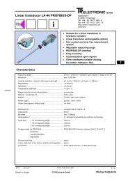
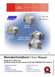
CE-65 / CE-100<br />
PROFIBUS-DP<br />
Encoder<br />
Operating Manual<br />
Encoder with Parameterization via<br />
Profibus according to PNO Profile Class 2<br />
Please keep for future reference !<br />
Edition/rev.: 15.03.2001<br />
Document/rev. no.: <strong>TR</strong> - ECE - BA - GB - 0009 - 07<br />
Software version: 4.00+ / WIU00001<br />
Filename:<br />
<strong>TR</strong>-ECE-BA-GB-0009.DOC<br />
Author:<br />
WIU / MÜJ<br />
<strong>TR</strong> - <strong>Electronic</strong> <strong>GmbH</strong><br />
Eglishalde 6<br />
D-78647 Trossingen<br />
Telephone + 49 (0) 7425/ 228-0<br />
Telefax + 49 (0) 7425/ 228-33<br />
Enclosed Disk<br />
Art.-No.: 490-00406
Operating Manual CE-65 / 100 PROFIBUS-DP (PNO)<br />
<strong>ELEC<strong>TR</strong>ONIC</strong> <strong>GmbH</strong><br />
Impressum<br />
<strong>TR</strong>-<strong>Electronic</strong> <strong>GmbH</strong><br />
D-78647 Trossingen<br />
Eglishalde 6<br />
Tel.: (0049) 07425/228-0<br />
Fax: (0049) 07425/228-33<br />
© Copyright 1997 <strong>TR</strong>-<strong>Electronic</strong><br />
Right of modification<br />
We reserve the right to modify the technical information contained in this document<br />
without prior notice in the interests of ongoing improvements to our products and<br />
documentation.<br />
Printing<br />
This manual was produced on a DOS personal computer using MS-Word for Windows<br />
6.0. The text was printed in Arial type.<br />
Notation<br />
Italics or bold type are used for the title of a document or to emphasize text passages.<br />
Courier type is used for text which is visible on the screen/display and for software<br />
menu selections.<br />
″ < > ″ refers to keys on your computer keyboard (e.g. ).<br />
Copyright note ( ©)<br />
SIMATIC S5/7, STEP-5/7 and COM-ET-200 are registered trademarks of the<br />
SIEMENS corporation.<br />
PROFIBUS-DP and the PROFIBUS logo are registered trademarks of the Profibus<br />
User Organization (PNO)<br />
MS-DOS, MS-Windows and MS-Windows-95 are registered trademarks of the<br />
Microsoft corporation.<br />
<strong>TR</strong> - <strong>ELEC<strong>TR</strong>ONIC</strong> <strong>GmbH</strong>, Corporate Quality Management, Eglishalde 6, 78647 Trossingen, Tel. 07425-228-0, Fax 07425-228-33<br />
Date: 15.03.2001 <strong>TR</strong> - ECE - BA - GB - 0009 - 07 Page 2 of 44
Operating Manual CE-65 / 100 PROFIBUS-DP (PNO)<br />
<strong>ELEC<strong>TR</strong>ONIC</strong> <strong>GmbH</strong><br />
Table of Contents<br />
1 Safety ...........................................................................................................................................................6<br />
1.1 General hazard potential....................................................................................................................6<br />
1.2 Safety information ..............................................................................................................................6<br />
1.2.1 Hints on installation ............................................................................................................7<br />
1.2.1.1 Screening..................................................................................................................................................8<br />
1.2.1.2 General interference suppression measures .............................................................................................8<br />
1.3 Intended use ......................................................................................................................................9<br />
1.4 Authorised operators..........................................................................................................................10<br />
1.5 Safety measures at the assembly site ...............................................................................................10<br />
2 Transportation / device data......................................................................................................................11<br />
2.1 Transportation / storage.....................................................................................................................11<br />
2.2 Technical data....................................................................................................................................12<br />
2.2.1 Electrical ratings.................................................................................................................12<br />
2.2.2 Mechanical ratings .............................................................................................................13<br />
2.3 Assembly............................................................................................................................................14<br />
2.4 Connecting the Cable Screening to the Bus-Cap ..............................................................................15<br />
3 Device description / start-up .....................................................................................................................16<br />
3.1 PNO identification number .................................................................................................................16<br />
3.2 PNO certificate...................................................................................................................................16<br />
3.3 PNO encoder profile ..........................................................................................................................16<br />
3.4 Operating requirements .....................................................................................................................16<br />
3.5 Setting the station address.................................................................................................................16<br />
3.6 Bus termination ..................................................................................................................................17<br />
3.7 Baud rate............................................................................................................................................17<br />
3.8 Device master file ..............................................................................................................................17<br />
3.9 Configuration and parameterization...................................................................................................18<br />
3.9.1 Configuration......................................................................................................................18<br />
3.9.1.1 Class 1 16-bit resolution, identifier D0 (HEX): .........................................................................................18<br />
3.9.1.2 Class 1 32-bit resolution, identifier D1 (HEX): .........................................................................................18<br />
3.9.1.3 Class 2 16-bit resolution, identifier F0 (HEX):..........................................................................................19<br />
3.9.1.4 Class 2 32-bit resolution, identifier F1 (HEX):..........................................................................................19<br />
3.9.1.5 <strong>TR</strong>-mode position, identifier F1 (HEX):......................................................................................................20<br />
3.9.1.6 <strong>TR</strong>-mode position+velocity, identifier F1 (HEX): ........................................................................................21<br />
3.9.2 Parameterization ................................................................................................................22<br />
3.9.2.1 Code sequence:........................................................................................................................................22<br />
3.9.2.2 Class 2 functionality: .................................................................................................................................22<br />
3.9.2.3 Commissioning diagnostic control:............................................................................................................22<br />
3.9.2.4 Scaling function control: ............................................................................................................................22<br />
3.9.2.5 Measuring units per revolution: .................................................................................................................22<br />
3.9.2.6 Total measuring range [units] hi and total measuring range [units] lo........................................................23<br />
3.9.2.7 Revolutions numerator hi and revolutions numerator lo.............................................................................23<br />
3.9.2.8 Revolutions denominator...........................................................................................................................23<br />
3.9.2.9 Code SSI interface:...................................................................................................................................24<br />
3.9.2.10 Data bits SSI interface: ...........................................................................................................................24<br />
3.9.2.11 Code PROFIBUS interface:.....................................................................................................................24<br />
3.9.2.12 Preset 1 value [units] hi and preset 1 value [units] lo...............................................................................24<br />
<strong>TR</strong> - <strong>ELEC<strong>TR</strong>ONIC</strong> <strong>GmbH</strong>, Corporate Quality Management, Eglishalde 6, 78647 Trossingen, Tel. 07425-228-0, Fax 07425-228-33<br />
Date: 15.03.2001 <strong>TR</strong> - ECE - BA - GB - 0009 - 07 Page 3 of 44
Operating Manual CE-65 / 100 PROFIBUS-DP (PNO)<br />
<strong>ELEC<strong>TR</strong>ONIC</strong> <strong>GmbH</strong><br />
3.9.2.13 Preset 2 value [units] hi and preset 2 value [units] lo...............................................................................25<br />
3.9.2.14 Commissioning function ..........................................................................................................................25<br />
3.9.2.15 Short diagnostic (16 byte) .......................................................................................................................25<br />
3.9.2.16 Limit switch lower and upper limit............................................................................................................25<br />
3.9.2.17 Speed [1/n rpm] ......................................................................................................................................26<br />
3.9.3 Scaling function..................................................................................................................27<br />
3.9.3.1 Nominal configurations PNO Class 1+2 ....................................................................................................27<br />
3.9.3.2 Nominal configuration <strong>TR</strong>-mode position and <strong>TR</strong>-mode position+velocity .................................................28<br />
3.10 Preset adjustment ............................................................................................................................29<br />
3.11 Commissioning function (Teach-in function for linear axes)............................................................30<br />
3.11.1 Input/output configuration for teach-in..............................................................................31<br />
3.11.1.1 Assignment of the status byte .................................................................................................................31<br />
3.11.1.2 Assignment of the control byte ................................................................................................................31<br />
3.11.2 Teach-in procedure..........................................................................................................32<br />
3.12 Optional SSI interface ......................................................................................................................34<br />
3.12.1 Limitation of SSI interface ................................................................................................34<br />
4 Trouble-shooting and diagnostic facilities ..............................................................................................35<br />
4.1 Visual indicators .................................................................................................................................35<br />
4.1.1 Indicator states, green LED (STAT)...................................................................................35<br />
4.1.2 Indicator states, red LED (BF)............................................................................................35<br />
4.2 How to use the PROFIBUS diagnostics.............................................................................................36<br />
4.2.1 Standard diagnosis ............................................................................................................36<br />
4.2.1.1 Station status 1 .........................................................................................................................................37<br />
4.2.1.2 Station status 2 .........................................................................................................................................37<br />
4.2.1.3 Station status 3 .........................................................................................................................................37<br />
4.2.1.4 Master address .........................................................................................................................................38<br />
4.2.1.5 Manufacturer's identifier ............................................................................................................................38<br />
4.2.1.6 Length (in byte) of extended diagnosis......................................................................................................38<br />
4.2.2 Extended diagnosis............................................................................................................39<br />
4.2.2.1 Alarms.......................................................................................................................................................39<br />
4.2.2.2 Operating status........................................................................................................................................40<br />
4.2.2.3 Encoder type.............................................................................................................................................40<br />
4.2.2.4 Single-turn resolution ................................................................................................................................40<br />
4.2.2.5 Number of resolvable revolutions ..............................................................................................................40<br />
4.2.2.6 Additional alarms ......................................................................................................................................40<br />
4.2.2.7 Supported alarms......................................................................................................................................41<br />
4.2.2.8 Warnings...................................................................................................................................................41<br />
4.2.2.9 Supported warnings ..................................................................................................................................41<br />
4.2.2.10 Profile version .........................................................................................................................................41<br />
4.2.2.11 Software version .....................................................................................................................................42<br />
4.2.2.12 Operating hour counter ...........................................................................................................................42<br />
4.2.2.13 Offset value.............................................................................................................................................42<br />
4.2.2.14 Manufacturer-specific offset value...........................................................................................................42<br />
4.2.2.15 Number of increments per revolution.......................................................................................................42<br />
4.2.2.16 Measuring length in increments...............................................................................................................42<br />
4.2.2.17 Serial number..........................................................................................................................................42<br />
4.2.2.18 Manufacturer-specific diagnostics ...........................................................................................................42<br />
4.3 Other faults ........................................................................................................................................43<br />
5 Appendix......................................................................................................................................................44<br />
5.1 New in firmware versions 4.x opposite 3.x.........................................................................................44<br />
<strong>TR</strong> - <strong>ELEC<strong>TR</strong>ONIC</strong> <strong>GmbH</strong>, Corporate Quality Management, Eglishalde 6, 78647 Trossingen, Tel. 07425-228-0, Fax 07425-228-33<br />
Date: 15.03.2001 <strong>TR</strong> - ECE - BA - GB - 0009 - 07 Page 4 of 44
Operating Manual CE-65 / 100 PROFIBUS-DP (PNO)<br />
<strong>ELEC<strong>TR</strong>ONIC</strong> <strong>GmbH</strong><br />
Revision index<br />
i<br />
Note<br />
The cover of this document shows the current revision status and the corresponding<br />
date. Since each individual page has its own revision status and date in the footer,,<br />
different revision statuses may exist within the same document.<br />
Document produced: 07.07.1997<br />
Revision<br />
Date<br />
Complete revision 04.03.1998<br />
Rearrangement of list of parameters for individual set<br />
configurations.<br />
Supplementation of information on device-specific diagnostics.<br />
05.11.1998<br />
Description of the firmware extension 3.x to 4.x. 22.11.2000<br />
- Notes for the use of the device master file "<strong>TR</strong>05AAAB.GSD"<br />
- Validity of this manual also for the device CE-100<br />
15.03.2001<br />
<strong>TR</strong> - <strong>ELEC<strong>TR</strong>ONIC</strong> <strong>GmbH</strong>, Corporate Quality Management, Eglishalde 6, 78647 Trossingen, Tel. 07425-228-0, Fax 07425-228-33<br />
Date: 15.03.2001 <strong>TR</strong> - ECE - BA - GB - 0009 - 07 Page 5 of 44
Operating Manual CE-65 / 100 PROFIBUS-DP (PNO)<br />
<strong>ELEC<strong>TR</strong>ONIC</strong> <strong>GmbH</strong><br />
1 Safety<br />
1.1 General hazard potential<br />
The rotary encoder cannot function as a stand-alone unit, i.e. it is a component part<br />
that is intended to be installed in a complete system consisting of several such<br />
components working together. For this reason, the rotary encoder does not have a<br />
protective device of its own.<br />
The encoder provides no diagnostics for errors that may occur, e.g. speed too high,<br />
track errors, transfer errors, etc. This means that you must check the received data<br />
yourself for validity.<br />
All persons involved in the assembly, start-up and operation of the device<br />
• must be appropriately qualified<br />
• must follow the instructions in this manual exactly.<br />
This is for your own safety and the safety of your equipment!<br />
1.2 Safety information<br />
This operating manual contains information which must be complied with to ensure<br />
your personal safety and to avoid damage to property. The information is emphasized<br />
by warning triangles, which have different appearances according to the degree of<br />
danger:<br />
Warning<br />
Means that death, severe injury or considerable damage to property can occur if the<br />
relevant safety measures are ignored.<br />
i<br />
Caution<br />
Means that slight injury or damage to property can occur if the relevant safety<br />
measures are ignored.<br />
Note<br />
Emphasizes important information about the product, its properties or helpful hints for<br />
using it.<br />
<strong>TR</strong> - <strong>ELEC<strong>TR</strong>ONIC</strong> <strong>GmbH</strong>, Corporate Quality Management, Eglishalde 6, 78647 Trossingen, Tel. 07425-228-0, Fax 07425-228-33<br />
Date: 15.03.2001 <strong>TR</strong> - ECE - BA - GB - 0009 - 07 Page 6 of 44
Operating Manual CE-65 / 100 PROFIBUS-DP (PNO)<br />
<strong>ELEC<strong>TR</strong>ONIC</strong> <strong>GmbH</strong><br />
1.2.1 Hints on installation<br />
In view of the fact that the rotary encoder is normally used as a component part of a<br />
larger system, this information is intended as a guideline for the safe integration of the<br />
rotary encoder into its environment.<br />
Warning<br />
• Observe the safety and accident prevention regulations relevant to the specific<br />
application.<br />
• In the case of equipment with a fixed connection (stationary installations/systems)<br />
without all-pole mains switches and/or fuses, you must install a mains switch or<br />
fuse in the system and connect the equipment to a protective earth conductor.<br />
• Before starting up devices that are run on mains voltage, check to make sure the<br />
set rated voltage range matches the local mains voltage.<br />
• With a 24-V supply, ensure safe electrical isolation of the extra-low voltage. Only<br />
use mains units that comply with the standards IEC 364-4-41 or HD 384.04.41<br />
(VDE 0100 Part 410).<br />
• Fluctuations or deviations from the rated mains voltage may not exceed the<br />
tolerances stated in the technical data. If they do, functional failures of the electrical<br />
components and hazardous conditions cannot be ruled out.<br />
• You must take precautions to ensure that an interrupted program can be resumed<br />
normally following voltage dips and failures. In this context, no dangerous operating<br />
status conditions may occur even for a brief period of time. If necessary, you must<br />
force an EMERGENCY STOP.<br />
• EMERGENCY STOP devices that comply with EN 60204/IEC 204 (VDE 0113)<br />
must remain effective in all the operating modes of the automation equipment.<br />
Unlocking the EMERGENCY STOP devices must not result in an uncontrolled or<br />
undefined restart.<br />
• Install the connecting and signal lines so that inductive and capacitive interference<br />
does not adversely affect the automation functions.<br />
• Install automation technology equipment and its operator input elements so that<br />
they are sufficiently protected against accidental actuation.<br />
• Take appropriate hardware and software precautions in the I/O link to prevent<br />
possible cable or wire breakages on the signal side leading to undefined status<br />
conditions in the automation equipment.<br />
<strong>TR</strong> - <strong>ELEC<strong>TR</strong>ONIC</strong> <strong>GmbH</strong>, Corporate Quality Management, Eglishalde 6, 78647 Trossingen, Tel. 07425-228-0, Fax 07425-228-33<br />
Date: 15.03.2001 <strong>TR</strong> - ECE - BA - GB - 0009 - 07 Page 7 of 44
Operating Manual CE-65 / 100 PROFIBUS-DP (PNO)<br />
<strong>ELEC<strong>TR</strong>ONIC</strong> <strong>GmbH</strong><br />
1.2.1.1 Screening<br />
The use of electronic sensor active systems in modern machines necessitates a<br />
consistent and correctly executed interference suppression and wiring strategy.<br />
These conditions are the only guarantee that systems containing electronic measuring<br />
systems will function properly.<br />
Recommended screened cable wiring<br />
Switching Cabinet<br />
Measuring Systems<br />
Machine<br />
Control Unit<br />
0V bar with screen<br />
terminal for measuring<br />
system cable<br />
Power Unit<br />
Measuring system<br />
and control<br />
cable<br />
Power Cable<br />
Ground cable 10 mm²<br />
(R ground cable
Operating Manual CE-65 / 100 PROFIBUS-DP (PNO)<br />
<strong>ELEC<strong>TR</strong>ONIC</strong> <strong>GmbH</strong><br />
1.3 Intended use<br />
The rotary encoder is used for registering angular movement and for pre-processing<br />
measuring data for a downstream controller.<br />
The encoder is designed to be run on PROFIBUS-DP networks according to DIN<br />
19245 Part 1-3 up to a maximum of 12 MBauds. The parameterization and equipment<br />
diagnostics are performed by the PROFIBUS master according to Version 1.1 of the<br />
PNO encoder profile.<br />
The PNO technical guidelines for setting up the PROFIBUS-DP network must be<br />
observed in all cases in order to ensure trouble-free operation.<br />
Warning<br />
De-energize the system before carrying out wiring or opening and closing<br />
electrical connections!<br />
Short-circuits, voltage peaks etc. can lead to malfunctions and uncontrolled states in<br />
the system or to serious personal injury or damage to property.<br />
Check all electrical connections before switching on the system!<br />
Connections that are made incorrectly can lead to system malfunctions; wrong<br />
connections may result in serious personal injury or damage to property.<br />
Mechanical or electrical modifications to the measuring systems are prohibited for<br />
safety reasons!<br />
Caution<br />
*Avoid excessive bearing loads due to radial and axial deviations between the<br />
encoder and the drive shaft!<br />
When assembling, you must use couplings that can absorb these forces.<br />
*Protect the encoder from excessive vibrations, shocks and jolts, e.g. on presses!<br />
Use "shock modules" to cushion vibrations.<br />
i<br />
Note<br />
Always follow the start-up, operating and programming instructions specified in this<br />
manual.<br />
* Observe the mechanical ratings on page 13.<br />
<strong>TR</strong> - <strong>ELEC<strong>TR</strong>ONIC</strong> <strong>GmbH</strong>, Corporate Quality Management, Eglishalde 6, 78647 Trossingen, Tel. 07425-228-0, Fax 07425-228-33<br />
Date: 15.03.2001 <strong>TR</strong> - ECE - BA - GB - 0009 - 07 Page 9 of 44
Operating Manual CE-65 / 100 PROFIBUS-DP (PNO)<br />
<strong>ELEC<strong>TR</strong>ONIC</strong> <strong>GmbH</strong><br />
1.4 Authorised operators<br />
The start-up and operation of this device may only be performed by qualified<br />
personnel. In the context of the safety-related information in this document, the term<br />
"qualified personnel" refers to persons who are authorized to commission, ground and<br />
mark circuits, equipment and systems in accordance with recognized safety standards.<br />
1.5 Safety measures at the assembly site<br />
Warning<br />
Do not carry out welding if the encoder has already been wired up or is switched<br />
on!<br />
Potential fluctuations can destroy the encoder or impair its operation.<br />
i<br />
Keep to the supply voltage range: 11-27 V DC (+/- 5 % residual ripple)<br />
Note<br />
Ensure that the area around the assembly site is protected from corrosive media (acid,<br />
etc.)<br />
<strong>TR</strong> - <strong>ELEC<strong>TR</strong>ONIC</strong> <strong>GmbH</strong>, Corporate Quality Management, Eglishalde 6, 78647 Trossingen, Tel. 07425-228-0, Fax 07425-228-33<br />
Date: 15.03.2001 <strong>TR</strong> - ECE - BA - GB - 0009 - 07 Page 10 of 44
Operating Manual CE-65 / 100 PROFIBUS-DP (PNO)<br />
<strong>ELEC<strong>TR</strong>ONIC</strong> <strong>GmbH</strong><br />
2 Transportation / device data<br />
2.1 Transportation / storage<br />
Notes on transportation<br />
Do not drop the device or expose it to shocks or vibrations!<br />
Device contains an optical system with glass elements.<br />
Only use the original packaging!<br />
The wrong packaging material can cause damage to the device during transportation.<br />
Storage<br />
Storage temperature: -30 to +80°C<br />
Store in a dry place.<br />
<strong>TR</strong> - <strong>ELEC<strong>TR</strong>ONIC</strong> <strong>GmbH</strong>, Corporate Quality Management, Eglishalde 6, 78647 Trossingen, Tel. 07425-228-0, Fax 07425-228-33<br />
Date: 15.03.2001 <strong>TR</strong> - ECE - BA - GB - 0009 - 07 Page 11 of 44
Operating Manual CE-65 / 100 PROFIBUS-DP (PNO)<br />
<strong>ELEC<strong>TR</strong>ONIC</strong> <strong>GmbH</strong><br />
2.2 Technical data<br />
2.2.1 Electrical ratings<br />
Operating voltage: ............................................<br />
Max. current consumption: ..............................<br />
Output capacity:................................................<br />
Resolution:.........................................................<br />
Measuring range: ..............................................<br />
Output code:......................................................<br />
Baud rate:...........................................................<br />
11-27 V DC (+/- 5% residual ripple)<br />
< 350 mA at 11 V DC, < 150 mA at 27 V DC<br />
Max. 25 bits<br />
Max. 8192 increments per revolution (13 bits)<br />
4096 revolutions (12 bits)<br />
Binary<br />
12 Mbps<br />
Encoder interface:............................................. PROFIBUS-DP acc. to DIN 19245 Part 1-3<br />
Special features:................................................<br />
Programming is performed via the<br />
parameterization message at the start-up of the<br />
encoder or PROFIBUS-DP master<br />
SSI-OUT data interface<br />
Clock input:........................................<br />
Data output:.......................................<br />
Clock rate: .........................................<br />
Code:.................................................<br />
Operating temperature range: .........................<br />
Optocoupler<br />
RS422 (2-wire)<br />
80 kHz - 1MHz<br />
Programmable, left-justified<br />
0 to +60°C<br />
<strong>TR</strong> - <strong>ELEC<strong>TR</strong>ONIC</strong> <strong>GmbH</strong>, Corporate Quality Management, Eglishalde 6, 78647 Trossingen, Tel. 07425-228-0, Fax 07425-228-33<br />
Date: 15.03.2001 <strong>TR</strong> - ECE - BA - GB - 0009 - 07 Page 12 of 44
Operating Manual CE-65 / 100 PROFIBUS-DP (PNO)<br />
<strong>ELEC<strong>TR</strong>ONIC</strong> <strong>GmbH</strong><br />
2.2.2 Mechanical ratings<br />
Mechanically permissible speed: ....................<br />
Permissible shaft load:.....................................<br />
6000 rpm<br />
40 N axial, 60 N radial (at end of shaft)<br />
Minimum bearing lifetime:................................ 3.9 x 10 10 revolutions at:<br />
Operating speed: ..................................... 3000 rpm<br />
Shaft loading:........................................... 20 N axial, 30 N radial (at end of shaft)<br />
Operating temperature:............................ 60°C<br />
Max. angular acceleration: ............................... ≤ 10 4 rad/s 2<br />
Moment of inertia: ............................................. 2.5 x 10- 6 kg m 2<br />
Starting torque at 20°C: ....................................<br />
2 Ncm<br />
Vibration loading (50-2000Hz):......................... ≤ 100 m/s 2<br />
Shock loading (11ms):...................................... ≤ 1000 m/s 2<br />
<strong>TR</strong> - <strong>ELEC<strong>TR</strong>ONIC</strong> <strong>GmbH</strong>, Corporate Quality Management, Eglishalde 6, 78647 Trossingen, Tel. 07425-228-0, Fax 07425-228-33<br />
Date: 15.03.2001 <strong>TR</strong> - ECE - BA - GB - 0009 - 07 Page 13 of 44
Operating Manual CE-65 / 100 PROFIBUS-DP (PNO)<br />
<strong>ELEC<strong>TR</strong>ONIC</strong> <strong>GmbH</strong><br />
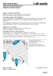
2.3 Assembly<br />
Encoder shaft drive<br />
Encoders of the CE series are connected to the drive shaft by an elastic coupling which<br />
compensates for any deviations in the axial and radial direction between the encoder and<br />
drive shaft. This avoids excessive strain on the bearings. Couplings can be ordered on<br />
request.<br />
Flange mounting<br />
The centering collar with fit f7 centers the encoder in relation to the shaft. It is fixed to<br />
the machine by means of three screws in the flange (Fig. 1).<br />
Clamping bracket mounting<br />
The centering collar with fit f7 centers the encoder in relation to the shaft. The encoder<br />
is fixed by means of two clamping brackets (Fig. 2).<br />
Fig. 1<br />
Coupling<br />
Absolute encoder<br />
Machine<br />
Fig. 2<br />
Coupling<br />
Absolute encoder<br />
Machine<br />
Clamping bracket<br />
<strong>TR</strong> - <strong>ELEC<strong>TR</strong>ONIC</strong> <strong>GmbH</strong>, Corporate Quality Management, Eglishalde 6, 78647 Trossingen, Tel. 07425-228-0, Fax 07425-228-33<br />
Date: 15.03.2001 <strong>TR</strong> - ECE - BA - GB - 0009 - 07 Page 14 of 44
Operating Manual CE-65 / 100 PROFIBUS-DP (PNO)<br />
<strong>ELEC<strong>TR</strong>ONIC</strong> <strong>GmbH</strong><br />
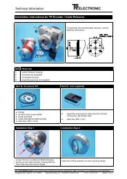
2.4 Connecting the Cable Screening to the Bus-Cap<br />
To prevent disturbance signals entering the encoder housing, we used cable screw<br />
glands with which it is possible to connect the screen on the inside. For this reason, no<br />
connection point for the screen is provided inside the cup-cap.<br />
Procedure:<br />
1. Screw the cable screw gland into the housing.<br />
2. Dismount the compression nut (1) and the terminal holder (2).<br />
3. Push the compression nut (1) and the terminal holder (2) over the cable.<br />
4. Strip the cable; push back the braiding around the terminal holder (2) such that the<br />
braiding goes over the inner O-ring (3) and does not lie over the cylindrical section<br />
or the torsional bars.<br />
5. Insert the terminal holder (2) into the intermediate gland (4) such that the torsional<br />
bars fit into the intended lengthwise grooves in the intermediate gland (4).<br />
6. Screw the compression nut (1) to the intermediate gland (4).<br />
Part 1<br />
Compression nut<br />
Part 2<br />
Terminal holder<br />
Part 3<br />
Inner O-ring<br />
Part 4<br />
Intermediate gland<br />
<strong>TR</strong> - <strong>ELEC<strong>TR</strong>ONIC</strong> <strong>GmbH</strong>, Corporate Quality Management, Eglishalde 6, 78647 Trossingen, Tel. 07425-228-0, Fax 07425-228-33<br />
Date: 15.03.2001 <strong>TR</strong> - ECE - BA - GB - 0009 - 07 Page 15 of 44
Operating Manual CE-65 / 100 PROFIBUS-DP (PNO)<br />
<strong>ELEC<strong>TR</strong>ONIC</strong> <strong>GmbH</strong><br />
3 Device description / start-up<br />
3.1 PNO identification number<br />
The encoder has the PNO ID number AAAB (hex). This number is reserved and filed<br />
with the PNO.<br />
3.2 PNO certificate<br />
The encoder has passed a certification test by an independent test laboratory of the<br />
Profibus User Organization and is certified under the number Z00319. The relevant<br />
documents are held by <strong>TR</strong> <strong>Electronic</strong> and the PNO.<br />
3.3 PNO encoder profile<br />
The Profibus User Organization has issued an encoder profile defining the structure of<br />
an encoder on the Profibus. A copy of this profile can be obtained for a fee from the<br />
PNO office. Details of prices are available exclusively by the Profibus User<br />
Organization.<br />
3.4 Operating requirements<br />
Theoretically, the encoder can be connected to any Profibus-DP network, provided the<br />
PROFIBUS-DP master is capable of transmitting a parameter message. Similarly, the<br />
configuration software should be able to display the parameter structure specified in<br />
the device master file in order to allow the parameters to be entered. If this is not the<br />
case, the encoder cannot be programmed and runs on the bus with the maximum<br />
resolution, and without the possibility of scaling or adjustment as Class-1 encoder.<br />
<strong>TR</strong> <strong>Electronic</strong> supplies a disk containing the device master file (.GSD) and a type file<br />
(.200) for users with SIEMENS masters. If the disk is not enclosed with this<br />
documentation, it can be ordered quoting reference number 490-00406.<br />
For details of how to integrate the encoder into the interface of the DP master<br />
configuration software, please refer to the relevant documentation.<br />
3.5 Setting the station address<br />
The station address of the encoder is set exclusively via the rotary switch in the cover<br />
containing the connecting terminals. When the terminals are viewed from above<br />
(outgoing cable facing downwards), the left-hand switch sets the tens and the righthand<br />
switch the units of the station address.<br />
The addressing of the encoder is limited within the Profibus address area. Valid station<br />
addresses are 3 - 99.<br />
If an invalid station address is set, the device will not start up and the LEDs will not be<br />
illuminated.<br />
<strong>TR</strong> - <strong>ELEC<strong>TR</strong>ONIC</strong> <strong>GmbH</strong>, Corporate Quality Management, Eglishalde 6, 78647 Trossingen, Tel. 07425-228-0, Fax 07425-228-33<br />
Date: 15.03.2001 <strong>TR</strong> - ECE - BA - GB - 0009 - 07 Page 16 of 44
Operating Manual CE-65 / 100 PROFIBUS-DP (PNO)<br />
<strong>ELEC<strong>TR</strong>ONIC</strong> <strong>GmbH</strong><br />
3.6 Bus termination<br />
All PROFIBUS networks must be terminated by a resistor at the ends of the bus<br />
segments. The matching resistor and resistors for connecting to the data reference<br />
potential are located in the cover with the terminals, and can be connected via DIL<br />
switches if necessary, provided the encoder is the last station of a bus segment. As a<br />
general rule, both switches must always be switched on (if encoder is the last station)<br />
or switched off (if the encoder is not the last station).<br />
3.7 Baud rate<br />
The Baud rate at which the PROFIBUS is operated may lie within the range of 9.6<br />
kBaud to 12 Mbaud, and is detected automatically by the encoder.<br />
3.8 Device master file<br />
For encoders with version 3.x, the device master file of the encoder has the filename<br />
<strong>TR</strong>03AAAB.GSD. Because of the extended performance range, for devices with<br />
version 4 and up the file *<strong>TR</strong>05AAAB.GSD was created.<br />
For users of older Siemens masters, there is also a so-called type file called<br />
<strong>TR</strong>AAAB3X.200 which fulfils the same function as the device master file<br />
<strong>TR</strong>03AAAB.GSD, but has a special data format.<br />
To find out how to integrate these files into the system configuration, please refer to<br />
the documentation of the configuration program for the Profibus master.<br />
The encoder also has two bitmap files named <strong>TR</strong>AAAB3N.BMP and <strong>TR</strong>AAAB3S.BMP<br />
or <strong>TR</strong>AAAB5N.DIP and <strong>TR</strong>AAAB5S.DIP which represent the encoder in the normal<br />
and faulty states respectively. These images also have to be integrated into the system<br />
configuration according to the instructions of the relevant documentation.<br />
* Usable as of COMPROFIBUS version 5.0 (S5) or STEP7 as of version 5.0 service<br />
pack 3 (S7).<br />
The file <strong>TR</strong>05AAAB.GSD causes:<br />
- 4 byte parameter (see also notes on page 26)<br />
(no partitioning into high and low word at decimal input)<br />
- Extended performance range<br />
- Teach In<br />
- Limit switches<br />
- switchable diagnostic length<br />
- switchable units for rev. per min<br />
see also chapter "New in firmware versions 4.x opposite 3.x", page 44.<br />
<strong>TR</strong> - <strong>ELEC<strong>TR</strong>ONIC</strong> <strong>GmbH</strong>, Corporate Quality Management, Eglishalde 6, 78647 Trossingen, Tel. 07425-228-0, Fax 07425-228-33<br />
Date: 15.03.2001 <strong>TR</strong> - ECE - BA - GB - 0009 - 07 Page 17 of 44
Operating Manual CE-65 / 100 PROFIBUS-DP (PNO)<br />
<strong>ELEC<strong>TR</strong>ONIC</strong> <strong>GmbH</strong><br />
3.9 Configuration and parameterization<br />
3.9.1 Configuration<br />
Configuration means specifying the length and type of process data and the manner in<br />
which they are to be handled. For this purpose, the configuration program usually<br />
provides an input list in which the user has to enter the appropriate identifiers.<br />
Since the encoder supports several possible configurations, the identifier to be entered<br />
is preset depending on the required nominal configuration, so that all you have to do is<br />
enter the I/O addresses. The identifiers are deposited in the device master file.<br />
Depending on the required nominal configuration, the encoder will assign a different<br />
number of input and output words on the PROFIBUS.<br />
In the following, the individual nominal configurations and the position of the<br />
communication bytes for the data transfer with the PROFIBUS-DP master are<br />
described.<br />
3.9.1.1 Class 1 16-bit resolution, identifier D0 (HEX):<br />
The encoder uses one input word only, which is consistently transferred via the bus.<br />
Input word IW x<br />
MSB<br />
Data byte 1 Data byte 0<br />
Input byte x+0 Input byte x+1<br />
LSB<br />
Relevant parameter data:<br />
• Count direction<br />
3.9.1.2 Class 1 32-bit resolution, identifier D1 (HEX):<br />
The encoder uses two input words only, which are consistently transferred via the bus.<br />
Double input word ID x<br />
MSB<br />
Data byte 3 Data byte 2 Data byte 1 Data byte 0<br />
Input byte x+0 Input byte x+1 Input byte x+2 Input byte x+3<br />
LSB<br />
i<br />
Relevant parameter data:<br />
• Count direction<br />
Note:<br />
In the case of configurations for CLASS 1, preset adjustment is not possible via the<br />
PROFIBUS, and only the code sequence can be changed. The encoder operates with<br />
the standard resolution specified on the rating plate. The diagnostic data are limited to<br />
16 bytes.<br />
<strong>TR</strong> - <strong>ELEC<strong>TR</strong>ONIC</strong> <strong>GmbH</strong>, Corporate Quality Management, Eglishalde 6, 78647 Trossingen, Tel. 07425-228-0, Fax 07425-228-33<br />
Date: 15.03.2001 <strong>TR</strong> - ECE - BA - GB - 0009 - 07 Page 18 of 44
Operating Manual CE-65 / 100 PROFIBUS-DP (PNO)<br />
<strong>ELEC<strong>TR</strong>ONIC</strong> <strong>GmbH</strong><br />
3.9.1.3 Class 2 16-bit resolution, identifier F0 (HEX):<br />
The encoder uses one input word and one output word which are consistently<br />
transferred via the bus.<br />
Input word IW x<br />
MSB<br />
Data byte 1 Data byte 0<br />
Input byte x+0 Input byte x+1<br />
LSB<br />
Output word for preset adjustment OW x<br />
MSB<br />
Data byte 1 Data byte 0<br />
P<br />
Output byte x+0 Output byte x+1<br />
LSB<br />
Relevant parameter data:<br />
• Count direction<br />
• Class 2 functionality (on/off)<br />
• Scaling function (on/off)<br />
• Commissioning diagnostic control (on/off)<br />
• Measuring units per revolution<br />
• Total measuring range<br />
3.9.1.4 Class 2 32-bit resolution, identifier F1 (HEX):<br />
The encoder uses two input words and two output words which are consistently<br />
transferred via the bus.<br />
Double input word ID x<br />
MSB<br />
Data byte 3 Data byte 2 Data byte 1 Data byte 0<br />
Input byte x+0 Input byte x+1 Input byte x+2 Input byte x+3<br />
LSB<br />
Double output word for preset adjustment OD x<br />
MSB<br />
Data byte 3 Data byte 2 Data byte 1 Data byte 0<br />
P<br />
Output byte x+0 Output byte x+1 Output byte x+2 Output byte x+3<br />
LSB<br />
Relevant parameter data:<br />
• Count direction<br />
• Class 2 functionality (on/off)<br />
• Scaling function (on/off)<br />
• Commissioning diagnostic control (on/off)<br />
• Measuring units per revolution<br />
• Total measuring range<br />
<strong>TR</strong> - <strong>ELEC<strong>TR</strong>ONIC</strong> <strong>GmbH</strong>, Corporate Quality Management, Eglishalde 6, 78647 Trossingen, Tel. 07425-228-0, Fax 07425-228-33<br />
Date: 15.03.2001 <strong>TR</strong> - ECE - BA - GB - 0009 - 07 Page 19 of 44
Operating Manual CE-65 / 100 PROFIBUS-DP (PNO)<br />
<strong>ELEC<strong>TR</strong>ONIC</strong> <strong>GmbH</strong><br />
3.9.1.5 <strong>TR</strong>-mode position, identifier F1 (HEX):<br />
The encoder uses two input words and two output words which are consistently<br />
transferred via the bus.<br />
Double input word ID x<br />
MSB<br />
Data byte 3 Data byte 2 Data byte 1 Data byte 0<br />
Input byte x+0 Input byte x+1 Input byte x+2 Input byte x+3<br />
LSB<br />
Double output word for preset adjustment OD x<br />
MSB<br />
Data byte 3 Data byte 2 Data byte 1 Data byte 0<br />
P<br />
Output byte x+0 Output byte x+1 Output byte x+2 Output byte x+3<br />
LSB<br />
Relevant parameter data:<br />
• Count direction<br />
• Commissioning diagnostic control (on/off)<br />
• Total measuring range<br />
• Revolutions numerator<br />
• Revolutions denominator<br />
• Code SSI interface 1<br />
• Code PROFIBUS interface<br />
• Preset 1 value (24V inputs)<br />
• Preset 2 value (24V inputs)<br />
New in version 4.x<br />
• Teach-In function (commissioning function)<br />
• Short diagnostic<br />
• Limit switch lower limit<br />
• Limit switch upper limit<br />
1 SSI on request, not standard<br />
<strong>TR</strong> - <strong>ELEC<strong>TR</strong>ONIC</strong> <strong>GmbH</strong>, Corporate Quality Management, Eglishalde 6, 78647 Trossingen, Tel. 07425-228-0, Fax 07425-228-33<br />
Date: 15.03.2001 <strong>TR</strong> - ECE - BA - GB - 0009 - 07 Page 20 of 44
Operating Manual CE-65 / 100 PROFIBUS-DP (PNO)<br />
<strong>ELEC<strong>TR</strong>ONIC</strong> <strong>GmbH</strong><br />
3.9.1.6 <strong>TR</strong>-mode position+velocity, identifier F1 (HEX):<br />
The encoder uses two input words for the position plus a separate input word for the<br />
velocity, and two output words which are consistently transferred via the bus. The<br />
velocity is output with a sign in revolutions per minute and has an accuracy of +/- 1<br />
rpm.<br />
Double input word ID x<br />
MSB<br />
Data byte 3 Data byte 2 Data byte 1 Data byte 0<br />
Input byte x+0 Input byte x+1 Input byte x+2 Input byte x+3<br />
LSB<br />
Input word IW x<br />
MSB<br />
Data byte 1 Data byte 0<br />
Input byte x+0 Input byte x+1<br />
LSB<br />
Double output word for preset adjustment OD x<br />
MSB<br />
Data byte 3 Data byte 2 Data byte 1 Data byte 0<br />
P<br />
Output byte x+0 Output byte x+1 Output byte x+2 Output byte x+3<br />
LSB<br />
Relevant parameter data:<br />
• Count direction<br />
• Commissioning diagnostic control (on/off)<br />
• Total measuring range<br />
• Revolutions numerator<br />
• Revolutions denominator<br />
• Code SSI interface 2<br />
• Code PROFIBUS interface<br />
• Preset 1 value (24V inputs)<br />
• Preset 2 value (24V inputs)<br />
i<br />
New in version 4.x<br />
• Teach-In function (commissioning function)<br />
• Short diagnostic<br />
• Limit switch lower limit<br />
• Limit switch upper limit<br />
• Speed [1/n rpm]<br />
Important note:<br />
The configurations designated "<strong>TR</strong> mode" are not compatible with the PNO encoder<br />
profile in terms of the parameter record. The scaling function prescribed by the PNO<br />
profile is a simple special case of a general gear. Due to the extended 'gear' scaling<br />
function, additional parameters are therefore necessary in order to describe the gear<br />
fully.<br />
In other words, the <strong>TR</strong>-specific modes represent an extension of the encoder function<br />
which is not restricted by its compatibility with the PROFIBUS-DP and certification.<br />
2 SSI on request, not standard<br />
<strong>TR</strong> - <strong>ELEC<strong>TR</strong>ONIC</strong> <strong>GmbH</strong>, Corporate Quality Management, Eglishalde 6, 78647 Trossingen, Tel. 07425-228-0, Fax 07425-228-33<br />
Date: 15.03.2001 <strong>TR</strong> - ECE - BA - GB - 0009 - 07 Page 21 of 44
Operating Manual CE-65 / 100 PROFIBUS-DP (PNO)<br />
<strong>ELEC<strong>TR</strong>ONIC</strong> <strong>GmbH</strong><br />
3.9.2 Parameterization<br />
Parameterization means providing a PROFIBUS-DP slave with certain information<br />
required for operating purposes before it begins the cyclical exchange of process data.<br />
For example, the encoder requires data concerning the resolution, count direction,<br />
preset values, etc.<br />
The configuration program for the PROFIBUS-DP master usually provides an input<br />
mask via which the user can enter the parameter data or select from lists. The<br />
structure of the input mask is stored in the device master file. The number and type of<br />
the parameters to be entered by the user depend on the chosen nominal configuration.<br />
3.9.2.1 Code sequence:<br />
Defines the count direction of the encoder.<br />
Selection<br />
• Increasing clockwise *<br />
• Increasing counter-clockwise<br />
3.9.2.2 Class 2 functionality:<br />
Defines the encoder's range of functions.<br />
"Class 2 deactivated" means that the encoder only performs Class 1 functions, does<br />
not scale the position value and is not adjustable.<br />
Selection<br />
• No<br />
• Yes<br />
(Class 2 functions deactivated)*<br />
(Class 2 activated)<br />
3.9.2.3 Commissioning diagnostic control:<br />
Defines whether the encoder outputs an extended diagnostic message.<br />
Selection<br />
• Disabled<br />
• Enabled<br />
(Commissioning diagnostic control deactivated)*<br />
(Commissioning diagnostic control activated)<br />
3.9.2.4 Scaling function control:<br />
Defines whether the encoder scales the position on the basis of the subsequent<br />
parameter. If Class 2 is deactivated, it does not scale the position value and is not<br />
adjustable.<br />
Selection<br />
• Disabled<br />
• Enabled<br />
(scaling deactivated)*<br />
(scaling activated)<br />
3.9.2.5 Measuring units per revolution:<br />
Defines the number of increments displayed by the encoder for each revolution of the<br />
encoder shaft.<br />
Input<br />
• Lower limit: 1 increment / revolution<br />
• Upper limit: 8192 increments per revolution (depending on capacity -<br />
marked on rating plate)<br />
• Default value: 4096<br />
<strong>TR</strong> - <strong>ELEC<strong>TR</strong>ONIC</strong> <strong>GmbH</strong>, Corporate Quality Management, Eglishalde 6, 78647 Trossingen, Tel. 07425-228-0, Fax 07425-228-33<br />
Date: 15.03.2001 <strong>TR</strong> - ECE - BA - GB - 0009 - 07 Page 22 of 44
Operating Manual CE-65 / 100 PROFIBUS-DP (PNO)<br />
<strong>ELEC<strong>TR</strong>ONIC</strong> <strong>GmbH</strong><br />
3.9.2.6 Total measuring range [units] hi and total measuring range [units] lo<br />
Together, these parameters define the total number of increments displayed by the<br />
encoder before it starts again from zero.<br />
Inputs for HI word<br />
• Lower limit 0<br />
• Upper limit 512 (depending on the total capacity, which is calculated by<br />
multiplying the max. number of increments per revolution by<br />
the maximum number of revolutions. This data is marked on<br />
the rating plate.)<br />
• Default value: 256<br />
Inputs for LO word<br />
• Lower limit 0<br />
• Upper limit 65535 (depending on the total capacity, which is calculated by<br />
multiplying the max. number of increments per revolution by<br />
the maximum number of revolutions. This data is marked on<br />
the rating plate.)<br />
• Default value: 0<br />
3.9.2.7 Revolutions numerator hi and revolutions numerator lo<br />
Together, these parameters define the total number of revolutions displayed by the<br />
encoder before it starts again from zero.<br />
Inputs for HI word<br />
• Lower limit 0<br />
• Upper limit 3<br />
• Default value: 0<br />
Inputs for LO word<br />
• Lower limit 1<br />
• Upper limit 65535<br />
• Default value: 4096<br />
3.9.2.8 Revolutions denominator<br />
Together, these parameters define the total number of revolutions displayed by the<br />
encoder before it starts again from zero.<br />
• Lower limit 1<br />
• Upper limit 99<br />
• Default value: 1<br />
<strong>TR</strong> - <strong>ELEC<strong>TR</strong>ONIC</strong> <strong>GmbH</strong>, Corporate Quality Management, Eglishalde 6, 78647 Trossingen, Tel. 07425-228-0, Fax 07425-228-33<br />
Date: 15.03.2001 <strong>TR</strong> - ECE - BA - GB - 0009 - 07 Page 23 of 44
Operating Manual CE-65 / 100 PROFIBUS-DP (PNO)<br />
<strong>ELEC<strong>TR</strong>ONIC</strong> <strong>GmbH</strong><br />
3.9.2.9 Code SSI interface:<br />
Defines the output code for the (optional) SSI interface. The transfer to the PROFIBUS<br />
takes place in binary form according to the PNO profile.<br />
Selection<br />
• Gray (encoder supplies 24-bit Gray code)<br />
• Binary (encoder supplies 24-bit binary code)*<br />
• Shifted Gray (encoder supplies clipped Gray code)<br />
3.9.2.10 Data bits SSI interface:<br />
Defines the number of data bits on the SSI interface.<br />
Output format: MSB left-justified<br />
• Lower limit 8<br />
• Upper limit 32<br />
• Default value 24<br />
3.9.2.11 Code PROFIBUS interface:<br />
Defines the output code for the PROFIBUS interface.<br />
Selection<br />
• Binary (encoder supplies 24-bit binary code)<br />
• Gray (encoder supplies 24-bit Gray code)*<br />
• Shifted Gray (encoder supplies clipped Gray code)<br />
3.9.2.12 Preset 1 value [units] hi and preset 1 value [units] lo<br />
Together, these parameters define the position value to which the encoder is adjusted<br />
with the leading edge of the 1st preset input. To suppress interference, however, the<br />
preset is only carried out if the preset signal is present without interruption during the<br />
entire response time of 30 ms. A re-execution of the preset is not possible until the<br />
input signal has been reset again and a filter time of 30 ms has been waited.<br />
The inputs depend on the total measuring length in increments<br />
• Lower limit 0<br />
• Upper limit total measuring length in increments - 1<br />
• Default value 1<br />
<strong>TR</strong> - <strong>ELEC<strong>TR</strong>ONIC</strong> <strong>GmbH</strong>, Corporate Quality Management, Eglishalde 6, 78647 Trossingen, Tel. 07425-228-0, Fax 07425-228-33<br />
Date: 15.03.2001 <strong>TR</strong> - ECE - BA - GB - 0009 - 07 Page 24 of 44
Operating Manual CE-65 / 100 PROFIBUS-DP (PNO)<br />
<strong>ELEC<strong>TR</strong>ONIC</strong> <strong>GmbH</strong><br />
3.9.2.13 Preset 2 value [units] hi and preset 2 value [units] lo<br />
Together, these parameters define the position value to which the encoder is adjusted<br />
with the leading edge of the 2nd preset input. To suppress interference, however, the<br />
preset is only carried out if the preset signal is present without interruption during the<br />
entire response time of 30 ms. A re-execution of the preset is not possible until the<br />
input signal has been reset again and a filter time of 30 ms has been waited.<br />
The inputs depend on the total measuring length in increments<br />
• Lower limit 0<br />
• Upper limit total measuring length in increments - 1<br />
• Default value 2<br />
3.9.2.14 Commissioning function<br />
This parameter defines the setting of the commissioning function. In the standard<br />
setting "Off, no status" the encoder is compatible to encoders with version 3.x (further<br />
details see Teach-In function).<br />
Selection<br />
• Off, no status (V3.x), default<br />
• Off, with status<br />
• On, with status<br />
3.9.2.15 Short diagnostic (16 byte)<br />
With this parameter in the <strong>TR</strong> operation modes the number of diagnostic bytes can be<br />
limited from 6+51 bytes to 6+10 bytes. Therefore the encoder can be operated also to<br />
Profibus masters with older issue numbers in these modes.<br />
Selection<br />
• No, default<br />
• Yes<br />
3.9.2.16 Limit switch lower and upper limit<br />
Is the status switched on (see commissioning function) the encoder can inform the<br />
master via a bit whether the actual value is within the limits.<br />
It is valid:<br />
Limit switch bit = 0<br />
Limit switch bit = 1<br />
if lower limit < actual value < upper limit<br />
if actual value < lower limit or actual value > upper limit<br />
The inputs depend on the total measuring length in increments.<br />
• Lower limit 0<br />
• Upper limit total measuring length in increments - 1<br />
• Default value 0<br />
<strong>TR</strong> - <strong>ELEC<strong>TR</strong>ONIC</strong> <strong>GmbH</strong>, Corporate Quality Management, Eglishalde 6, 78647 Trossingen, Tel. 07425-228-0, Fax 07425-228-33<br />
Date: 15.03.2001 <strong>TR</strong> - ECE - BA - GB - 0009 - 07 Page 25 of 44
Operating Manual CE-65 / 100 PROFIBUS-DP (PNO)<br />
<strong>ELEC<strong>TR</strong>ONIC</strong> <strong>GmbH</strong><br />
3.9.2.17 Speed [1/n rpm]<br />
With this parameter the information of the rotation speed can be scaled in arbitrary<br />
increments between 1/1 and 1/100 rpm.<br />
i<br />
• Lower limit 1<br />
• Upper limit 100<br />
• Default value 1<br />
Notes for the input of parameters with data format 32 bits<br />
(only in connection with the device master file "<strong>TR</strong>03AAAB.GSD")<br />
The Profibus standard DIN 19245 provides the data format "UNSIGNED32" for the<br />
definition of 32 bits of parameter data in the device master file. This data format isn't<br />
supported by all configuration programs for profibus master. These programs clip the<br />
more significant word of the parameter. In order to allow inputs despite this, these<br />
parameters are split up into single words.<br />
Illogically enough, the input in the input masks also has to be made in decimal form.<br />
This affects the following parameters:<br />
• Total measuring range [units]<br />
• Revolutions numerator<br />
• Preset 1 value<br />
• Preset 2 value<br />
In the meantime, we recommend the following procedure for entering measuring<br />
lengths in increments larger than 16 bits:<br />
1. Convert the desired measuring length in increments to a hexadecimal figure using<br />
a calculator and store this figure.<br />
2. Convert only the four less significant tetrads (figures) back to decimal format<br />
separately. This gives you the input 'Total measuring range [units] lo'<br />
3. Convert only the remaining more significant tetrads (figures) back to decimal format<br />
separately. This gives you the input 'Total measuring range [units] hi'<br />
Example:<br />
Total measuring length in increments:<br />
converted to hexadecimals:<br />
results in four less significant tetrads:<br />
and remaining more significant tetrads:<br />
10 500 000 (D)<br />
A0 37A0 (H)<br />
37A0 (H)<br />
A0 (H)<br />
Total measuring range [units] lo: 14240 (D) (=37A0 (H) !)<br />
Total measuring range [units] hi: 160 (D) (=A0 (H) !)<br />
<strong>TR</strong> - <strong>ELEC<strong>TR</strong>ONIC</strong> <strong>GmbH</strong>, Corporate Quality Management, Eglishalde 6, 78647 Trossingen, Tel. 07425-228-0, Fax 07425-228-33<br />
Date: 15.03.2001 <strong>TR</strong> - ECE - BA - GB - 0009 - 07 Page 26 of 44
Operating Manual CE-65 / 100 PROFIBUS-DP (PNO)<br />
<strong>ELEC<strong>TR</strong>ONIC</strong> <strong>GmbH</strong><br />
3.9.3 Scaling function<br />
3.9.3.1 Nominal configurations PNO Class 1+2<br />
The encoder does not support a gear function. The position value is decoded in binary<br />
form and balanced against a zero offset and the code sequence.<br />
The position is calculated according to the following formula:<br />
Measuring length in increments *<br />
Number of increments per revolution * = -------------------------------------------------<br />
Number of revolutions<br />
i<br />
Important Notes<br />
When entering the parameterization data, make sure the parameters 'Measuring<br />
length in increments' and 'Number of increments per revolution' are chosen so<br />
that the quotient of the two parameters is a second power.<br />
If this is not the case, the encoder will correct the measuring length in<br />
increments to the next smallest second power in revolutions. The number of<br />
increments per revolution remains constant.<br />
The re-calculated measuring length in increments can be read out via the<br />
extended diagnostic information for Class 2 and is always smaller than the<br />
predefined measuring length. Therefore it can be that the actually needed total<br />
increment number is exceeded and the encoder generates a zero-point<br />
changeover before reaching the maximum mechanical displacement distance.<br />
Since the internal absolute position (before the encoder was scaled and a zeropoint<br />
adjustment was executed) recurs periodically after 4096 revolutions, at<br />
rotating applications (endless driving to the same direction, the number of<br />
revolutions is not a power of two) it comes inevitably to offsets.<br />
For such applications, one of the <strong>TR</strong> - nominal configurations has to be used.<br />
* Operator input<br />
<strong>TR</strong> - <strong>ELEC<strong>TR</strong>ONIC</strong> <strong>GmbH</strong>, Corporate Quality Management, Eglishalde 6, 78647 Trossingen, Tel. 07425-228-0, Fax 07425-228-33<br />
Date: 15.03.2001 <strong>TR</strong> - ECE - BA - GB - 0009 - 07 Page 27 of 44
Operating Manual CE-65 / 100 PROFIBUS-DP (PNO)<br />
<strong>ELEC<strong>TR</strong>ONIC</strong> <strong>GmbH</strong><br />
3.9.3.2 Nominal configuration <strong>TR</strong>-mode position and <strong>TR</strong>-mode position+velocity<br />
The encoder supports the gear function for rotating applications. The position value is<br />
balanced against a zero offset, the code sequence and the entered gear parameters.<br />
The number of increments per revolution is calculated according to the following<br />
formula:<br />
Measuring length in increments *<br />
Number of increments per revolution = ------------------------------------------------------<br />
Number of revolutions numerator *<br />
------------------------------------------------------<br />
Number of revolutions denominator *<br />
Gear limits:<br />
Maximum no. of revolutions 256000<br />
Minimum no. of revolutions 1<br />
Maximum no. of increments per revolution see encoder rating plate<br />
Minimum denominator 1<br />
Maximum denominator 99<br />
i<br />
Important Notes<br />
For rotating applications (endless driving to the same direction, the number of<br />
revolutions must not to be a power of two), one of the <strong>TR</strong> - nominal<br />
configurations must to be used.<br />
<strong>TR</strong> - <strong>ELEC<strong>TR</strong>ONIC</strong> <strong>GmbH</strong>, Corporate Quality Management, Eglishalde 6, 78647 Trossingen, Tel. 07425-228-0, Fax 07425-228-33<br />
Date: 15.03.2001 <strong>TR</strong> - ECE - BA - GB - 0009 - 07 Page 28 of 44
Operating Manual CE-65 / 100 PROFIBUS-DP (PNO)<br />
<strong>ELEC<strong>TR</strong>ONIC</strong> <strong>GmbH</strong><br />
3.10 Preset adjustment<br />
In 'Class 2' mode and in the '<strong>TR</strong> - operation modes', the PROFIBUS can be used to<br />
adjust the encoder to any position value within a range of 0 to (measuring length in<br />
increments - 1).<br />
This is done by setting the most significant bits of the output data (2 31 for configuration<br />
Class 2 - 32 bits or 2 15 for configuration Class 2 - 16 bits).<br />
Outputs<br />
Data byte 3 Data byte 2 Data byte 1 Data byte 0<br />
MSB P<br />
Output byte x+0 Output byte x+1 Output byte x+2 Output byte x+3<br />
LSB<br />
Inputs<br />
Data byte 3 Data byte 2 Data byte 1 Data byte 0<br />
MSB<br />
Input byte x+0 Input byte x+1 Input byte x+2 Input byte x+3<br />
LSB<br />
The preset adjustment value transferred in data bytes 0 - 3 is accepted as the position<br />
value with the leading edge of bit 32 (=bit 7 of data byte 3).<br />
To suppress interference, however, the new position value is only carried out if the<br />
control bit 32 is present without interruption during the entire response time of 30 ms.<br />
A re-adjustment is not possible until the control bit has been reset again and a filter<br />
time of 30 ms has been waited.<br />
In the Class 2 mode this process is not acknowledged via the inputs.<br />
In the <strong>TR</strong> - operations modes at status switched-on (see adjustments of the<br />
Commissioning function) this process is acknowledged via the most significant bit.<br />
<strong>TR</strong> - <strong>ELEC<strong>TR</strong>ONIC</strong> <strong>GmbH</strong>, Corporate Quality Management, Eglishalde 6, 78647 Trossingen, Tel. 07425-228-0, Fax 07425-228-33<br />
Date: 15.03.2001 <strong>TR</strong> - ECE - BA - GB - 0009 - 07 Page 29 of 44
Operating Manual CE-65 / 100 PROFIBUS-DP (PNO)<br />
<strong>ELEC<strong>TR</strong>ONIC</strong> <strong>GmbH</strong><br />
3.11 Commissioning function (Teach-in function for linear axes)<br />
This function is activatable in the parameterization.<br />
When the commissioning function is activated, the relevant distance can be traversed<br />
with the machine. On the basis of the input "requested number of units per distance<br />
traveled", the encoder automatically calculates its measuring length in increments from<br />
the position difference and the selected measuring units. This value can then be<br />
entered in the parameterization file, so that the teach-in process does not need to be<br />
repeated should the encoder be exchanged.<br />
For the Teach-In procedure following reductions are valid:<br />
• The number of the revolutions must be programmed fixed to 4096 and may not be<br />
changed in the parameterization!<br />
• The maximum displacement distance mustn't exceed 2048 revolutions<br />
• During the Teach-In process the maximum number of increments per revolution of<br />
the encoder mustn't be exceeded (e.g. specification of a measuring length of 3000<br />
increments and indication of a displacement distance of ¼ of a revolution)<br />
• For rotating applications the commissioning function is not suitable and not valid<br />
When the teach-in function is activated, the green LED flashes at a frequency of<br />
approx. 1 Hz.<br />
To remain downward compatible to the version of 3.x, in the parameter setting there<br />
are three different settings:<br />
• OFF, no status:<br />
This setting is compatible with version 3.x, that means the bits 2 25 to 2 31 are<br />
always "0".<br />
• OFF, with status:<br />
In this setting the status bits are visible, but the function is not activated<br />
• ON, with status<br />
The commissioning function is active<br />
<strong>TR</strong> - <strong>ELEC<strong>TR</strong>ONIC</strong> <strong>GmbH</strong>, Corporate Quality Management, Eglishalde 6, 78647 Trossingen, Tel. 07425-228-0, Fax 07425-228-33<br />
Date: 15.03.2001 <strong>TR</strong> - ECE - BA - GB - 0009 - 07 Page 30 of 44
Operating Manual CE-65 / 100 PROFIBUS-DP (PNO)<br />
<strong>ELEC<strong>TR</strong>ONIC</strong> <strong>GmbH</strong><br />
3.11.1 Input/output configuration for teach-in<br />
Outputs<br />
Requested no. of units per distance travelled<br />
Control bits+Distance 2 24 Distance 2 23 -2 16 Distance 2 15 -2 8 Distance 2 7 -2 0<br />
MSB<br />
LSB<br />
Output byte x+0 Output byte x+1 Output byte x+2 Output byte x+3<br />
Inputs<br />
Position / Measuring length in steps<br />
MSB<br />
Status+Position 2 24 Position 2 23 -2 16 Position 2 15 -2 8 Position 2 7 -2 0 LSB<br />
Input byte x+0 Input byte x+1 Input byte x+2 Input byte x+3<br />
3.11.1.1 Assignment of the status byte<br />
At activated status the status bits 2 25 to 2 31 have the following meaning:<br />
Bit 25<br />
Bit 26<br />
Bit 27<br />
Bit 28<br />
Bit 29<br />
Bit 30<br />
Bit 31<br />
Ready status<br />
0 = Encoder not ready-to-operate<br />
1 = Encoder ready-to-operate<br />
Operating mode<br />
0 = Commissioning mode<br />
1 = Normal mode<br />
Software limit switches<br />
0 = lower limit switch < process-actual value < upper limit switch<br />
1 = process-actual value < lower limit switch or<br />
process-actual value > upper limit switch<br />
Counting direction (at the moment)<br />
Bit 28 = 0: Counting direction cw (with look on the shaft)<br />
Bit 28 = 1: Counting direction ccw (with look on the shaft)<br />
Teach-In, takeover drive distance<br />
0 = Drive distance not taken<br />
1 = Drive distance taken<br />
Start Teach-In<br />
0 = No start<br />
1 = Teach-In function started<br />
Adjustment acknowledgement<br />
0 = No adjustment requested<br />
1= Requested adjustment was executed<br />
3.11.1.2 Assignment of the control byte<br />
Bit 25<br />
Bit 26<br />
Bit 27<br />
Bit 28<br />
Bit 29<br />
Bit 30<br />
Bit 31<br />
No meaning<br />
No meaning<br />
No meaning<br />
Change counting direction<br />
0 = Keep counting direction<br />
1 = Invert present counting direction<br />
Takeover Teach-In<br />
0 = No takeover of the drive distance<br />
1 = Takeover of the drive distance<br />
Start Teach-In<br />
0 = No start<br />
1 = Start<br />
Adjustment request<br />
0 = No adjustment requested<br />
1 = Adjust encoder to the preset value<br />
<strong>TR</strong> - <strong>ELEC<strong>TR</strong>ONIC</strong> <strong>GmbH</strong>, Corporate Quality Management, Eglishalde 6, 78647 Trossingen, Tel. 07425-228-0, Fax 07425-228-33<br />
Date: 15.03.2001 <strong>TR</strong> - ECE - BA - GB - 0009 - 07 Page 31 of 44
Operating Manual CE-65 / 100 PROFIBUS-DP (PNO)<br />
<strong>ELEC<strong>TR</strong>ONIC</strong> <strong>GmbH</strong><br />
3.11.2 Teach-in procedure<br />
The teach-in procedure takes place in several stages which are described below. It is<br />
assumed that the PROFIBUS is in operation, that the PLC is in its cycle, and that its<br />
process image is continuously updated. The inputs and outputs assigned by the<br />
encoder in the PLC must be able to be controlled via a programming device (e.g.<br />
"Control variables" function in SIMATIC-S5 system), or alternatively by a PLC handling<br />
facility.<br />
1. After selecting manual or set-up mode, move the machine by hand to the starting<br />
position of the distance to be measured.<br />
2. Find out whether the present adjusted counting direction is correct for the<br />
application. If not, first the counting direction must be inverted with setting the<br />
"Change counting direction" bit in the control byte. The encoder displays the<br />
present counting direction in the status byte.<br />
3. Set the "Start Teach-In" bit in the control byte<br />
The encoder then re-programs its measuring length in increments to the maximum<br />
resolution, memorizes its current position and acknowledges this process by setting<br />
the "Teach In Function Started" bit in the status byte.<br />
4. Reset the "Start Teach-In" bit in the control byte<br />
The "Teach-In Started" bit remains set furthermore!<br />
5. In manual or set-up mode, move the machine by hand to the ending position of the<br />
distance to be measured. Measure the distance between initial and ending position<br />
with a measuring tape of arbitrary measurement unit.<br />
6. Enter the real distance in measured units according to the tape measure in data<br />
bytes D0 and D1 of the outputs.<br />
7. Set the "Takeover of the drive distance" bit in the control byte<br />
The encoder then calculates the measuring length in increments from the<br />
requested travelling distance in measured units, enters the calculated measuring<br />
length in increments in data bytes D0 .. D2 of the inputs and acknowledges this<br />
process by setting the "Teach-In, drive distance taken" bit of the status<br />
byte.<br />
8. Make a note of the measuring length in increments!<br />
9. Reset the "Takeover of the drive distance" bit in the control byte<br />
The encoder then accordingly resets the "Teach-In started" and "Teach-In,<br />
drive distance taken" bits in the status byte. Thus the Teach-In process is<br />
completed.<br />
10. Carry out presetting or adjustment.<br />
If one of the steps was omitted or incompletely executed, the entire procedure must be<br />
repeated.<br />
During the teach-in process, the encoder must not be adjusted and no presettings may<br />
be performed.<br />
Once all axes have been set up with the teach-in function, the noted measuring<br />
lengths in increments must be entered in the parameterization file of the encoder using<br />
the configuration program for the PROFIBUS master (e.g. COM-ET-200 or COM<br />
PROFIBUS), and the teach-in mode must be deactivated. This ensures that the teachin<br />
process does not have to be repeated should the encoder be exchanged.<br />
<strong>TR</strong> - <strong>ELEC<strong>TR</strong>ONIC</strong> <strong>GmbH</strong>, Corporate Quality Management, Eglishalde 6, 78647 Trossingen, Tel. 07425-228-0, Fax 07425-228-33<br />
Date: 15.03.2001 <strong>TR</strong> - ECE - BA - GB - 0009 - 07 Page 32 of 44
Operating Manual CE-65 / 100 PROFIBUS-DP (PNO)<br />
<strong>ELEC<strong>TR</strong>ONIC</strong> <strong>GmbH</strong><br />
The following tables display the processes schematically again:<br />
Setting of the counting direction<br />
M = Master Status-/Control bits Data bits<br />
S = Slave Bit 31 30 29 28 27 26 25 24 23 22 21 20 19 18 17 16 15 14 13 12 11 10 9 8 7 6 5 4 3 2 1 0<br />
M!S 0 0 0 1 0 0 0 The selected direction of rotation is changed over from 0 to 1 or 1 to 0 using bit 28<br />
S!M<br />
The encoder now acknowledges the newly selected direction of ro. in bit 0 and bit<br />
0 0 0 0/1 0/1 0 1<br />
28<br />
M!S 0 0 0 0 0 0 0 Changeover is completed by setting bit 28 to 0<br />
S!M 0 0 0 0/1 0/1 0 1 The process actual value is now output again<br />
0/1<br />
Teach-In Start<br />
M = Master Status-/Control bits Data bits<br />
S = Slave Bit 31 30 29 28 27 26 25 24 23 22 21 20 19 18 17 16 15 14 13 12 11 10 9 8 7 6 5 4 3 2 1 0<br />
M!S 0 1 0 0 0 0 0 The Teach-In mode is activated by setting bit 30<br />
S!M 0 1 0 0/1 0/1 0 1 Acknowledging by setting bit 30 to 1 0/1<br />
M!S 0 0 0 0 0 0 0 Resetting<br />
S!M 0 1 0 0/1 0/1 0 1 Non-calculated process actual values (gear factor=1, no preset active)<br />
Teach-In, takeover drive distance<br />
M = Master Status-/Control bits Data bits<br />
S = Slave Bit 31 30 29 28 27 26 25 24 23 22 21 20 19 18 17 16 15 14 13 12 11 10 9 8 7 6 5 4 3 2 1 0<br />
M!S 0 0 1 0 0 0 0 Number of increments which the encoder should output is now sent to the encoder<br />
S!M<br />
Transfer of the total measuring range for the new gear factor (this should be<br />
0 1 1 0/1 0/1 0 1<br />
noted!)<br />
M!S 0 0 0 0 0 0 0 Resetting<br />
S!M 0 0 0 0/1 0/1 0 1 The process actual value, calculated with the new gear factor, is output<br />
0/1<br />
Preset-Adjustment<br />
M = Master Status-/Control bits Data bits<br />
S = Slave Bit 31 30 29 28 27 26 25 24 23 22 21 20 19 18 17 16 15 14 13 12 11 10 9 8 7 6 5 4 3 2 1 0<br />
M!S 1 0 0 0 0 0 0 Here the preset value is transferred as desired new actual value<br />
S!M 0 0 0 0 0 0 0 The encoder acknowledges the takeover in bit 7 of the status byte<br />
M!S 0 0 0 0 0 0 0 By setting the bit 31 to 0, the adjustment is finished<br />
S!M 0 0 0 0 0 0 0 The process actual value is now output again<br />
<strong>TR</strong> - <strong>ELEC<strong>TR</strong>ONIC</strong> <strong>GmbH</strong>, Corporate Quality Management, Eglishalde 6, 78647 Trossingen, Tel. 07425-228-0, Fax 07425-228-33<br />
Date: 15.03.2001 <strong>TR</strong> - ECE - BA - GB - 0009 - 07 Page 33 of 44
Operating Manual CE-65 / 100 PROFIBUS-DP (PNO)<br />
<strong>ELEC<strong>TR</strong>ONIC</strong> <strong>GmbH</strong><br />
3.12 Optional SSI interface<br />
The encoder has a separate Synchronous Serial Interface via which its position value<br />
can be made available to a further evaluation unit (e.g. drive controller).<br />
The position value output at this interface is identical to the value output on the<br />
PROFIBUS in terms of conversion and code sequence. In order to use this interface, a<br />
special cover with terminals for the SSI interface is necessary.<br />
3.12.1 Limitation of SSI interface<br />
The encoder position is re-loaded after each read process, and remains unchanged<br />
until the next time it is accessed. If the SSI master (e.g. drive controller or WF<br />
assembly) reads the position at prolonged or irregular intervals, this may lead to<br />
contouring error messages.<br />
To avoid this, the position should be read at short, regular intervals.<br />
The monoflop time of the SSI interface is around 35 - 55 µs (typ. 41 µs) as opposed to<br />
20 - 40 µs in the standard interface.<br />
<strong>TR</strong> - <strong>ELEC<strong>TR</strong>ONIC</strong> <strong>GmbH</strong>, Corporate Quality Management, Eglishalde 6, 78647 Trossingen, Tel. 07425-228-0, Fax 07425-228-33<br />
Date: 15.03.2001 <strong>TR</strong> - ECE - BA - GB - 0009 - 07 Page 34 of 44
Operating Manual CE-65 / 100 PROFIBUS-DP (PNO)<br />
<strong>ELEC<strong>TR</strong>ONIC</strong> <strong>GmbH</strong><br />
4 Trouble-shooting and diagnostic facilities<br />
4.1 Visual indicators<br />
The encoder is equipped with two LEDs in the bus cover: one red LED (BF) for<br />
indicating errors and one green LED (STAT) for indicating status information.<br />
When the encoder is started up, both LEDs flicker briefly. Thereafter, the indications<br />
depend on the operational status of the encoder.<br />
4.1.1 Indicator states, green LED (STAT)<br />
Green LED Cause Remedy<br />
Off Absence of voltage supply Check voltage supply wiring<br />
Station address incorrectly set Set station address (valid values 3-99 !)<br />
Flashing at a<br />
frequency of 10 Hz<br />
Bus cover not mounted and<br />
screwed on correctly<br />
Bus cover defective<br />
Hardware error, encoder<br />
defective<br />
Irreparable parameterization or<br />
configuration error.<br />
Check bus cover for correct seating<br />
Replace bus cover<br />
Replace encoder<br />
Check parameterization and configuration<br />
See section 3.9 on page 18<br />
Flashing at a<br />
frequency of 1 Hz<br />
Parameterization or<br />
configuration error in PNOcompatible<br />
nominal<br />
configuration<br />
Data have been corrected<br />
Check configuring and operational status of<br />
PROFIBUS master<br />
or<br />
On<br />
Teach-in mode active<br />
Encoder ready for operation<br />
Deactivate teach-in mode<br />
4.1.2 Indicator states, red LED (BF)<br />
Red LED Cause Remedy<br />
Off<br />
Flashing at a<br />
frequency of<br />
1 Hz<br />
No error, bus in cycle<br />
Encoder not yet addressed by<br />
master<br />
Check set station address<br />
Check configuring and operational status of<br />
PROFIBUS master<br />
On Irreparable encoder fault Check parameter data<br />
<strong>TR</strong> - <strong>ELEC<strong>TR</strong>ONIC</strong> <strong>GmbH</strong>, Corporate Quality Management, Eglishalde 6, 78647 Trossingen, Tel. 07425-228-0, Fax 07425-228-33<br />
Date: 15.03.2001 <strong>TR</strong> - ECE - BA - GB - 0009 - 07 Page 35 of 44
Operating Manual CE-65 / 100 PROFIBUS-DP (PNO)<br />
<strong>ELEC<strong>TR</strong>ONIC</strong> <strong>GmbH</strong><br />
4.2 How to use the PROFIBUS diagnostics<br />
In a Profibus system, the Profibus masters supply the process data to a so-called host<br />
system, e.g. a PLC-CPU. If a slave is not accessible, or no longer accessible, on the<br />
bus, or if the slave itself reports a fault, the master must communicate this fault to the<br />
host system in some form or other. There are several possible ways of doing this, the<br />
evaluation of which depends entirely on the application in the host system.<br />
As a general rule, a host system cannot be stopped following the failure of only one<br />
component on the bus, but must respond appropriately to the failure as prescribed by<br />
the safety regulations. The master normally provides the host system initially with a<br />
summary diagnosis, which the host system reads cyclically from the master, and which<br />
serves to report the states of the individual bus stations to the application. If a station is<br />
reported to be faulty in the summary diagnosis, the host can request further data from<br />
the master (slave diagnostics), which then allow a more detailed evaluation of the<br />
causes. The indications thus obtained may either have been generated by the master,<br />
if the relevant slave does not respond (or no longer responds) to the master's<br />
requests, or they may come directly from the slave, if the slave itself reports a fault.<br />
The generation or reading of the diagnostic message between the master and slave<br />
takes place automatically, and does not have to be programmed by the user.<br />
In addition to the standard diagnostic information, the encoder provides an extended<br />
diagnostic message according to Class 1 or Class 2 of the PNO encoder profile,<br />
depending on the nominal configuration.<br />
4.2.1 Standard diagnosis<br />
The standard DP diagnosis is structured as follows (always from the point of view of<br />
the master in relation to the slave).<br />
Byte no. Meaning<br />
Byte 1 Station status 1<br />
Byte 2 Station status 2<br />
Byte 3 Station status 3 General part<br />
Byte 4 Master address<br />
Byte 5 Manufacturer's identifier HI byte<br />
Byte 6 Manufacturer's identifier LO byte<br />
Byte 7 Length (in bytes) of extended<br />
diagnosis<br />
Byte 8 Other device-specific diagnoses Device-specific extensions<br />
to<br />
Byte 241<br />
(max)<br />
<strong>TR</strong> - <strong>ELEC<strong>TR</strong>ONIC</strong> <strong>GmbH</strong>, Corporate Quality Management, Eglishalde 6, 78647 Trossingen, Tel. 07425-228-0, Fax 07425-228-33<br />
Date: 15.03.2001 <strong>TR</strong> - ECE - BA - GB - 0009 - 07 Page 36 of 44
Operating Manual CE-65 / 100 PROFIBUS-DP (PNO)<br />
<strong>ELEC<strong>TR</strong>ONIC</strong> <strong>GmbH</strong><br />
4.2.1.1 Station status 1<br />
Bit 7 Master_Lock Slave has been parameterized<br />
by another master (bit is set by<br />
master)<br />
Bit 6 Parameter_Fault The last parameterization<br />
message to have been sent was<br />
rejected by the slave<br />
Bit 5 Invalid_Slave_Response Set by the master if the slave<br />
does not respond<br />
Bit 4 Not_Supported Slave does not support the<br />
requested functions<br />
Bit 3 Ext_Diag Bit = 1 means that there is an<br />
extended diagnostic message<br />
from the slave<br />
Bit 2 Slave_Cfg_Chk_Fault The configuration identifier(s)<br />
sent by the master was/were<br />
rejected by the slave<br />
Bit 1 Station_Not_Ready Slave is not ready to exchange<br />
cyclical data<br />
Bit 0 Station_Non_Existent The slave has been configured<br />
but is not present on the bus<br />
4.2.1.2 Station status 2<br />
Bit 7 Deactivated Slave has been deleted from the<br />
poll list by the master<br />
Bit 6 Reserved<br />
Bit 5 Sync_Mode Set by slave on receipt of SYNC<br />
command<br />
Bit 4 Freeze_Mode Set by slave on receipt of<br />
FREEZE command<br />
Bit 3 WD_On Slave watchdog is activated<br />
Bit 2 Slave_Status Always set for slaves<br />
Bit 1 Stat_Diag Static diagnosis<br />
Bit 0 Prm_Req The slave sets this bit if it has to<br />
be re-parameterized and reconfigured.<br />
4.2.1.3 Station status 3<br />
Bit 7 Ext_Diag_Overflow Overflow in extended diagnosis<br />
Bit 6 - 0 Reserved<br />
<strong>TR</strong> - <strong>ELEC<strong>TR</strong>ONIC</strong> <strong>GmbH</strong>, Corporate Quality Management, Eglishalde 6, 78647 Trossingen, Tel. 07425-228-0, Fax 07425-228-33<br />
Date: 15.03.2001 <strong>TR</strong> - ECE - BA - GB - 0009 - 07 Page 37 of 44
Operating Manual CE-65 / 100 PROFIBUS-DP (PNO)<br />
<strong>ELEC<strong>TR</strong>ONIC</strong> <strong>GmbH</strong><br />
4.2.1.4 Master address<br />
In this byte, the slave enters the station address of the first master to have sent a valid<br />
parameterization message. If several masters access the bus simultaneously, their<br />
configuration and parameterization information must coincide exactly in order to<br />
ensure correct operation of the Profibus.<br />
4.2.1.5 Manufacturer's identifier<br />
In bytes 5+6, the slave enters the manufacturer-specific identification number, an<br />
unambiguous number for each device type which is reserved and filed with the PNO.<br />
The identifier number of the encoder is AAAB(h).<br />
4.2.1.6 Length (in byte) of extended diagnosis<br />
If additional diagnostic information is available, the slave enters the number of bytes<br />
following the standard diagnosis here.<br />
<strong>TR</strong> - <strong>ELEC<strong>TR</strong>ONIC</strong> <strong>GmbH</strong>, Corporate Quality Management, Eglishalde 6, 78647 Trossingen, Tel. 07425-228-0, Fax 07425-228-33<br />
Date: 15.03.2001 <strong>TR</strong> - ECE - BA - GB - 0009 - 07 Page 38 of 44
Operating Manual CE-65 / 100 PROFIBUS-DP (PNO)<br />
<strong>ELEC<strong>TR</strong>ONIC</strong> <strong>GmbH</strong><br />
4.2.2 Extended diagnosis<br />
In addition to the standard DP diagnostic message, the encoder also provides an<br />
extended diagnostic message according to the PNO encoder profile. This message<br />
varies in length depending on the chosen nominal configuration. In the configurations<br />
designated "<strong>TR</strong> mode", the diagnostic message corresponds to PNO Class 2.<br />
The following pages provide a general overview of the available diagnostic information.<br />
Which individual options your encoder actually supports can be read out from the<br />
device itself.<br />
Byte no. Meaning Class<br />
Byte 7 Length (in bytes) of extended diagnosis 1<br />
Byte 8 Alarms 1<br />
Byte 9 Operating status 1<br />
Byte 10 Encoder type 1<br />
Byte 11-14 Encoder resolution in increments per revolution (rotary) 1<br />
Encoder resolution in measuring increments (linear)<br />
Byte 15-16 Number of resolvable revolutions 1<br />
Byte 17 Additional alarms 2<br />
Byte 18-19 Supported alarms 2<br />
Byte 20-21 Warnings 2<br />
Byte 22-23 Supported warnings 2<br />
Byte 24-25 Profile version 2<br />
Byte 26-27 Software version (firmware) 2<br />
Byte 28-31 Operating hour counter 2<br />
Byte 32-35 Offset value 2<br />
Byte 36-39 Manufacturer's offset value 2<br />
Byte 40-43 Number of increments per revolution 2<br />
Byte 44-47 Measuring length in increments 2<br />
Byte 48-57 Serial number 2<br />
Byte 58-59 Reserved 2<br />
Byte 60-63 Manufacturer-specific diagnostics Optional<br />
4.2.2.1 Alarms<br />
Bit Meaning = 0 = 1<br />
Bit 0 Position error No Yes<br />
Bit 1 Supply voltage faulty No Yes<br />
Bit 2 Current consumption too high No Yes<br />
Bit 3 Diagnosis OK Error<br />
Bit 4 Memory error No Yes<br />
Bit 5 Not applicable<br />
Bit 6 Not applicable<br />
Bit 7 Not applicable<br />
<strong>TR</strong> - <strong>ELEC<strong>TR</strong>ONIC</strong> <strong>GmbH</strong>, Corporate Quality Management, Eglishalde 6, 78647 Trossingen, Tel. 07425-228-0, Fax 07425-228-33<br />
Date: 15.03.2001 <strong>TR</strong> - ECE - BA - GB - 0009 - 07 Page 39 of 44
Operating Manual CE-65 / 100 PROFIBUS-DP (PNO)<br />
<strong>ELEC<strong>TR</strong>ONIC</strong> <strong>GmbH</strong><br />
4.2.2.2 Operating status<br />
Bit Meaning = 0 = 1<br />
Bit 0 Code sequence Increasing<br />
clockwise<br />
Bit 1 Class-2 functions No, not<br />
supported<br />
Bit 2 Diagnosis No, not<br />
supported<br />
Bit 3 Status scaling function No, not<br />
supported<br />
Bit 4 Not applicable<br />
Bit 5 Not applicable<br />
Bit 6 Not applicable<br />
Bit 7 Not applicable<br />
Increasing<br />
counterclockwise<br />
Yes<br />
Yes<br />
Yes<br />
4.2.2.3 Encoder type<br />
Code Meaning<br />
00 Single-turn absolute encoder (rotary)<br />
01 Multi-turn absolute encoder (rotary)<br />
See encoder profile for other codes<br />
4.2.2.4 Single-turn resolution<br />
The hardware single-turn resolution of the encoder can be read out via bytes 11-14.<br />
4.2.2.5 Number of resolvable revolutions<br />
The maximum number of encoder revolutions can be read out via diagnostic bytes 15-<br />
16.<br />
4.2.2.6 Additional alarms<br />
Byte 17 is reserved for additional alarms, although no other alarms are implemented.<br />
Bit Meaning = 0 = 1<br />
Bit 0-7<br />
Reserved<br />
<strong>TR</strong> - <strong>ELEC<strong>TR</strong>ONIC</strong> <strong>GmbH</strong>, Corporate Quality Management, Eglishalde 6, 78647 Trossingen, Tel. 07425-228-0, Fax 07425-228-33<br />
Date: 15.03.2001 <strong>TR</strong> - ECE - BA - GB - 0009 - 07 Page 40 of 44
Operating Manual CE-65 / 100 PROFIBUS-DP (PNO)<br />
<strong>ELEC<strong>TR</strong>ONIC</strong> <strong>GmbH</strong><br />
4.2.2.7 Supported alarms<br />
Bit Meaning = 0 = 1<br />
Bit 0 Position error Not supported Supported<br />
Bit 1 Supply voltage monitoring Not supported Supported<br />
Bit 2 Current consumption Not supported Supported<br />
monitoring<br />
Bit 3 Diagnostic routine Not supported Supported<br />
Bit 4 Memory error Not supported Supported<br />
Bit 5-15 Not applicable<br />
4.2.2.8 Warnings<br />
Bit Meaning = 0 = 1<br />
Bit 0 Frequency exceeded No Yes<br />
Bit 1 Permissible temp. exceeded No Yes<br />
Bit 2 Control reserve light Not reached Reached<br />
Bit 3 CPU watchdog status OK Reset performed<br />
Bit 4 Operating time warning No Yes<br />
Bit 5-15 Battery charge OK Too low<br />
4.2.2.9 Supported warnings<br />
Bit Meaning = 0 = 1<br />
Bit 0 Frequency exceeded Not supported Supported<br />
Bit 1 Permissible temp. exceeded Not supported Supported<br />
Bit 2 Control reserve light Not supported Supported<br />
Bit 3 CPU watchdog status Not supported Supported<br />
Bit 4 Operating time warning Not supported Supported<br />
Bit 5-15 Reserved<br />
4.2.2.10 Profile version<br />
Diagnostic bytes 24-25 indicate the version of the PNO encoder profile supported by<br />
the encoder. They consist of the revision number and revision index (e.g. 1.40<br />
corresponds to 0000 0001 0100 0000 or 0140 (hexadecimal code) )<br />
Byte 24<br />
Byte 25<br />
Revision number<br />
Revision index<br />
<strong>TR</strong> - <strong>ELEC<strong>TR</strong>ONIC</strong> <strong>GmbH</strong>, Corporate Quality Management, Eglishalde 6, 78647 Trossingen, Tel. 07425-228-0, Fax 07425-228-33<br />
Date: 15.03.2001 <strong>TR</strong> - ECE - BA - GB - 0009 - 07 Page 41 of 44
Operating Manual CE-65 / 100 PROFIBUS-DP (PNO)<br />
<strong>ELEC<strong>TR</strong>ONIC</strong> <strong>GmbH</strong><br />
4.2.2.11 Software version<br />
Diagnostic bytes 26-27 indicate the internal software version of the encoder. They<br />
consist of the revision number and revision index (e.g. 1.40 corresponds to 0000 0001<br />
0100 0000 or 0140 (hexadecimal code) )<br />
Byte 26<br />
Byte 27<br />
Revision number<br />
Revision index<br />
4.2.2.12 Operating hour counter<br />
Diagnostic bytes 28-31 represent an operating hour counter which is incremented by<br />
one digit every 6 minutes. The measuring unit for operating hours is thus 0.1 hours.<br />
If this function is not supported, the operating hour counter is set to the maximum<br />
value FFFFFFFF(hexadecimal code).<br />
4.2.2.13 Offset value<br />
Diagnostic bytes 32-35 indicate the offset in relation to the absolute scanning position<br />
which is calculated during the execution of the preset function.<br />
4.2.2.14 Manufacturer-specific offset value<br />
Diagnostic bytes 36-39 indicate an additional manufacturer-specific offset in relation to<br />
the absolute scanning position which is calculated during the execution of the preset<br />
function.<br />
4.2.2.15 Number of increments per revolution<br />
Diagnostic bytes 40-43 indicate the configured increments per revolution of the<br />
encoder.<br />
4.2.2.16 Measuring length in increments<br />
Diagnostic bytes 44-47 indicate the configured measuring lengths in increments of the<br />
encoder.<br />
4.2.2.17 Serial number<br />
Diagnostic bytes 48-57 indicate the serial number of the encoder. If this function is not<br />
supported, asterisks are used (hexadecimal code 0x2A) ********** to indicate the<br />
configured measuring length in increments of the encoder.<br />
4.2.2.18 Manufacturer-specific diagnostics<br />
The encoder does not support any other manufacturer-specific diagnostics.<br />
<strong>TR</strong> - <strong>ELEC<strong>TR</strong>ONIC</strong> <strong>GmbH</strong>, Corporate Quality Management, Eglishalde 6, 78647 Trossingen, Tel. 07425-228-0, Fax 07425-228-33<br />
Date: 15.03.2001 <strong>TR</strong> - ECE - BA - GB - 0009 - 07 Page 42 of 44
Operating Manual CE-65 / 100 PROFIBUS-DP (PNO)<br />
<strong>ELEC<strong>TR</strong>ONIC</strong> <strong>GmbH</strong><br />
i<br />
Important note<br />
According to the PNO encoder profile, an encoder must set the bits 'Ext.diag'<br />
(extended diagnostic information available) and 'Stat.diag' (static error) in the event of<br />
an internal error being detected in the station status. This means that, in case of error,<br />
the encoder stops providing position data and is removed from the process image by<br />
the PROFIBUS master until the error bits are reset. It is not possible for the user to<br />
acknowledge the error via the PROFIBUS in this way.<br />
This function is only guaranteed provided the Commissioning Diagnostic function is<br />
activated.<br />
4.3 Other faults<br />
Fault Cause Remedy<br />
Encoder step<br />
changes<br />
Profibus operates<br />
when the encoder is<br />
not connected, but<br />
indicates a fault when<br />
the bus cover is<br />
mounted on the<br />
encoder<br />
Strong vibrations<br />
Electrical faults<br />
EMC<br />
Excessive axial and<br />
radial loading of shaft<br />
or scanning defect.<br />
PROFIBUS Data-A<br />
and Data-B reversed<br />
Vibrations, shocks and jolts, e.g. on presses, are<br />
cushioned by so-called "shock modules". If the error<br />
persists despite these precautions, the encoder must be<br />
replaced.<br />
Electrical faults can be countered by means of insulating<br />
plastic flanges and couplings, and by data and power<br />
supply cables with twisted-pair conductors. The screening<br />
and wiring arrangement must conform to the assembly<br />
guidelines for PROFIBUS.<br />
Couplings prevent mechanical strain on the shaft. If the<br />
error persists despite this precaution, the encoder must be<br />
replaced..<br />
Inspect all connections and conductors relating to the<br />
wiring of the encoder.<br />
<strong>TR</strong> - <strong>ELEC<strong>TR</strong>ONIC</strong> <strong>GmbH</strong>, Corporate Quality Management, Eglishalde 6, 78647 Trossingen, Tel. 07425-228-0, Fax 07425-228-33<br />
Date: 15.03.2001 <strong>TR</strong> - ECE - BA - GB - 0009 - 07 Page 43 of 44
Operating Manual CE-65 / 100 PROFIBUS-DP (PNO)<br />
<strong>ELEC<strong>TR</strong>ONIC</strong> <strong>GmbH</strong><br />
5 Appendix<br />
5.1 New in firmware versions 4.x opposite 3.x<br />
• The till now optionally available commissioning function is activatable in version 4.x<br />
at full downward compatibility any time.<br />
• The reduction is cancelled, that the scaling function can be activated only in<br />
connection with the Class 2 functions. The device then works as Class 1 device<br />
with short diagnostic length and is nevertheless scalable.<br />
• In the <strong>TR</strong> operation modes the diagnostic length can be limited on the length of the<br />
Class 1 diagnosis.<br />
• If the status byte is activated a limit switch bit with two limit values is available to<br />
supervise the displacement range.<br />
• The information of the rotational speed is scalable in arbitrary steps between 1/1<br />
and 1/100 revolutions per minute.<br />
<strong>TR</strong> - <strong>ELEC<strong>TR</strong>ONIC</strong> <strong>GmbH</strong>, Corporate Quality Management, Eglishalde 6, 78647 Trossingen, Tel. 07425-228-0, Fax 07425-228-33<br />
Date: 15.03.2001 <strong>TR</strong> - ECE - BA - GB - 0009 - 07 Page 44 of 44