Pneumatic Actuated - KTH Sales, Inc.
Pneumatic Actuated - KTH Sales, Inc.
Pneumatic Actuated - KTH Sales, Inc.

Create successful ePaper yourself
Turn your PDF publications into a flip-book with our unique Google optimized e-Paper software.
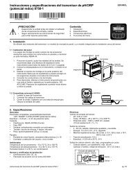
<strong>Pneumatic</strong> Automation<br />
Model SR / DA Actuators
Features and Benefits<br />
2<br />
1<br />
10<br />
9<br />
8<br />
3<br />
7<br />
4<br />
6<br />
5<br />
2<br />
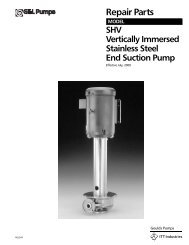
1. Steel Pinion<br />
Nickel plated for corrosion protection,<br />
to maximize wear resistance, and to<br />
reduce friction<br />
NAMUR slotted and threaded shaft<br />
allows for direct mounting of limit<br />
switches, positioners, and position<br />
monitors<br />
Bottom of pinion is ISO 5211<br />
2. Rotation Adjustment<br />
Adjustment ±5° in open and closed positions<br />
3. Die Cast Aluminum End Caps<br />
Standard polyester powder coated<br />
Nickel plating available<br />
4. High Tensile Steel Springs<br />
Zinc phosphate coated for corrosion resistance<br />
Spring sets easily changed to suit different air<br />
pressure/torque requirements<br />
5. Assembly Screw<br />
Stainless steel as standard<br />
6. Solenoid Valve Connection<br />
NAMUR pattern to permit direct<br />
mounting of solenoid valves<br />
7. Die Cast Aluminum Pistons<br />
Chemical nickel plating available<br />
8. Seals<br />
NBR-70 standard for temperatures<br />
ranging from -4°F to 185°F (-20°C<br />
to 85°C)<br />
Viton high temperature seals -4°F<br />
to 320°F (-20°C to 150°C)<br />
HNBR low temperature seals -40°F<br />
to 185°F (-40°C to 85°C)<br />
9. POM Piston Guides<br />
Large contact area<br />
Durable with low friction<br />
Self lubricating<br />
10. Extruded Aluminum Body<br />
UNI 6060 Aluminum<br />
Hard anodized finish to 45-50 micron<br />
for corrosion resistance and exceptional<br />
wear reduction<br />
Nickel plated or epoxy coated bodies<br />
available<br />
Top mounting pad drilled and tapped<br />
to NAMUR for direct mounting of<br />
accessories
Technical Data<br />
Type<br />
Model<br />
Cycle Time (seconds)<br />
32 52 63 75 85 100 115 125 160 200 270<br />
DA<br />
Counterclockwise<br />
Rotation<br />
0.03<br />
0.03<br />
0.06<br />
0.12<br />
0.20<br />
0.30<br />
0.53<br />
0.83<br />
1.15<br />
1.74<br />
4.50<br />
DA<br />
Clockwise Rotation<br />
0.03<br />
0.04<br />
0.08<br />
0.12<br />
0.19<br />
0.27<br />
0.47<br />
0.66<br />
1.10<br />
1.70<br />
4.50<br />
SR<br />
Counterclockwise<br />
Rotation<br />
-<br />
0.09<br />
0.14<br />
0.22<br />
0.31<br />
0.44<br />
0.83<br />
1.08<br />
1.75<br />
2.38<br />
4.50<br />
SR<br />
Clockwise Rotation<br />
-<br />
0.09<br />
0.14<br />
0.22<br />
0.33<br />
0.46<br />
0.78<br />
0.90<br />
1.34<br />
2.19<br />
6.20<br />
Approximate time per stroke (single direction) at 80 psi air supply without valve<br />
Weight (pounds)<br />
Model<br />
Type<br />
32 52 63 75 85 100 115 125 160 200 270<br />
DA 1.05<br />
2.30<br />
3.30<br />
5.60<br />
7.50<br />
11.15<br />
17.60<br />
22.05<br />
43.50<br />
72.30<br />
157.50<br />
SR<br />
-<br />
2.65<br />
3.95<br />
7.05<br />
9.50<br />
14.45<br />
22.35<br />
29.50<br />
53.80<br />
111.30<br />
194.00<br />
DA &<br />
SR<br />
DA<br />
SR<br />
Type<br />
Counterclockwise<br />
Rotation<br />
Clockwise Rotation<br />
Clockwise Rotation<br />
SR<br />
Model<br />
2.3<br />
CCW<br />
CW<br />
SR<br />
-<br />
CW 1.7<br />
Air Consumption (cubic inches)<br />
6.6<br />
9.3<br />
7.7<br />
Approximate standard cubic inches of air per stroke<br />
32 52 63 75 85 100 115 125 160 200 270<br />
12.1<br />
17.2<br />
14.2<br />
16.2<br />
20.5<br />
17.2<br />
30.2<br />
39.5<br />
32.4<br />
45.3<br />
66.8<br />
54.4<br />
61.0<br />
103.7<br />
85.4<br />
106.9<br />
148.5<br />
122.0<br />
220.1<br />
290.6<br />
215.1<br />
348.1<br />
599.7<br />
462.6<br />
915.4<br />
1086.2<br />
945.9<br />
Pressure<br />
Maximum Working<br />
Pressure:<br />
Temperature<br />
Standard Range:<br />
Option High Temp:<br />
Option Low Temp:<br />
116 psi (8 bar)<br />
-4°F to 185°F, NBR<br />
(-20°C to 85°C)<br />
-4°F to 320°F, Viton<br />
(-20°C to 150°C)<br />
-40°F to 185°F, HNBR<br />
(-40°C to 85°C)<br />
Mounting Options<br />
Closed<br />
Open<br />
Counterclockwise Rotation (Standard)<br />
Clockwise Rotation<br />
3
Parts and Materials<br />
Model 32<br />
Item Description Materials Treatment DA / Qty<br />
1<br />
Body<br />
Extruded Aluminum<br />
Hard Anodized<br />
1<br />
2<br />
3<br />
Anti-blowout Pinion Steel Nickel Plated<br />
1<br />
Lower Pinion O-Ring NBR 1<br />
4<br />
5<br />
Top Pinion O-Ring<br />
Spacer Ring<br />
NBR 1<br />
POM 1<br />
6<br />
7<br />
8<br />
9<br />
Pinion Snap Ring Steel Nickel Plated<br />
1<br />
Piston Die Cast Aluminum 2<br />
Piston O-Ring NBR 2<br />
Stop Bolt Stainless Steel 2<br />
10<br />
Stop Bolt O-Ring<br />
NBR<br />
2<br />
11<br />
12<br />
13<br />
14<br />
15<br />
16<br />
Washer Stainless Steel<br />
2<br />
Stop Bolt Retaining Nut Stainless Steel 2<br />
Left End Cap<br />
Die Cast Aluminum Painted<br />
1<br />
Right End Cap Die Cast Aluminum Painted<br />
1<br />
End Cap Seats<br />
NBR<br />
2<br />
End Cap Fixing Screw Stainless Steel<br />
8<br />
4
Parts and Materials<br />
Model 52 to 125<br />
Item Description Materials Treatment DA / Qty SR / Qty<br />
1<br />
Body<br />
Extruded Aluminum<br />
Hard Anodized<br />
1 1<br />
2<br />
Anti-blowout Pinion<br />
Steel<br />
Nickel Plated<br />
1 1<br />
3<br />
Lower Pinion O-Ring NBR 1 1<br />
4<br />
5<br />
Pinion Spacer Ring<br />
Top Pinion O-Ring<br />
POM 1 1<br />
NBR 1 1<br />
6<br />
7<br />
Cam Spacer Ring POM 1 1<br />
Cam Stainless Steel 1 1<br />
8<br />
9<br />
Position Indicator Nylon 2<br />
Pinion Washer Stainless Steel 1<br />
2<br />
1<br />
10<br />
Pinion Snap Ring<br />
Steel<br />
Nickel Plated<br />
1<br />
1<br />
11<br />
12<br />
13<br />
14<br />
15<br />
16<br />
17<br />
18<br />
19<br />
Piston Die Cast Aluminum<br />
2<br />
Piston O-Ring NBR 2<br />
Anti-friction Ring<br />
POM<br />
2<br />
Piston Thrust Block POM 2<br />
Stop Bolt Retaining Nut Stainless Steel<br />
2<br />
Stop Bolt<br />
Stainless Steel<br />
2<br />
External Spring<br />
Steel<br />
Zinc-Phosphate<br />
0<br />
Internal Spring<br />
Steel<br />
Zinc-Phosphate<br />
0<br />
Left End Cap<br />
Die Cast Aluminum Painted 1<br />
2<br />
2<br />
2<br />
2<br />
2<br />
2<br />
Based on<br />
Spring<br />
Setting<br />
1<br />
20<br />
Right End Cap<br />
Die Cast Aluminum<br />
Painted<br />
1<br />
1<br />
21<br />
End Cap Seats<br />
NBR<br />
2<br />
2<br />
22<br />
End Cap Fixing Screw<br />
Stainless Steel<br />
8<br />
8<br />
5
Parts and Materials<br />
Model 160 - 200 - 270<br />
Model 270 Only<br />
Closed position adjustment<br />
upon request<br />
Item Description Materials Treatment DA / Qty SR / Qty<br />
1<br />
2<br />
3<br />
4<br />
5<br />
6<br />
7<br />
8<br />
9<br />
10<br />
11<br />
12<br />
13<br />
14<br />
15<br />
16<br />
17<br />
18<br />
19<br />
20<br />
21<br />
22<br />
23<br />
24<br />
25<br />
Body<br />
Anti-blowout Pinion<br />
Extruded Aluminum<br />
Steel<br />
1 1<br />
1 1<br />
Lower Pinion O-Ring NBR 1 1<br />
Top Pinion O-Ring NBR 1 1<br />
Pinion Spacer Ring POM 1 1<br />
Pinion Snap Ring Steel Nickel Plated<br />
1 1<br />
Piston Die Cast Aluminum 2 2<br />
Piston O-Ring NBR 2<br />
Anti-friction Ring PTFE 15% Graphite 2<br />
Piston Thrust Block<br />
POM<br />
Stop Bolt O-Ring NBR<br />
2<br />
Washer Stainless Steel 2<br />
Stop Bolt Retaining Nut<br />
Stainless Steel<br />
Stop Bolt Stainless Steel 2<br />
External Spring<br />
Central Spring<br />
Internal Spring<br />
Left End Cap<br />
Right End Cap<br />
End Cap Fixing Screw<br />
End Cap O-Ring<br />
End Cap Fixing Screw<br />
Precompressed Spring<br />
Anti-friction Ring<br />
Pinion Washer<br />
Steel<br />
Steel<br />
Steel<br />
Die Cast Aluminum<br />
Die Cast Aluminum<br />
Stainless Steel<br />
NBR<br />
NBR<br />
Steel<br />
PTFE 15% Graphite<br />
Stainless Steel<br />
Hard Anodized<br />
Nickel Plated<br />
4 (6)*<br />
Zinc-Phosphate 0<br />
Zinc-Phosphate<br />
Zinc-Phosphate<br />
Painted<br />
Painted 1<br />
Zinc-Phosphate<br />
Closed Position Adjustment Upon Request<br />
2<br />
0<br />
0<br />
1<br />
8 (12)*<br />
2<br />
2<br />
0<br />
1<br />
1<br />
2<br />
2<br />
4 (6)*<br />
2<br />
2<br />
2<br />
2<br />
Based on<br />
Spring<br />
Setting<br />
1<br />
1<br />
8 (12)*<br />
2<br />
2<br />
Based on<br />
Spring Setting<br />
1<br />
1<br />
26<br />
Plate<br />
GGG40<br />
Painted<br />
1<br />
1<br />
27<br />
Coupling<br />
Steel<br />
Nickel Plated<br />
1<br />
1<br />
28<br />
Anti-friction Ring<br />
PTFE<br />
1<br />
1<br />
29<br />
Stop Screw<br />
Steel<br />
Zinc Plated<br />
1<br />
1<br />
30<br />
Stop Bolt Retaining Nut<br />
Stainless Steel<br />
1<br />
1<br />
6<br />
31 Fixing Screws<br />
Stainless Steel<br />
* (6) and (12) Valid for Model 270 Only<br />
4<br />
4
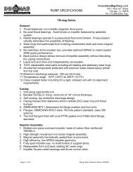
Sizing and Selection<br />
Double Acting Actuators<br />
Top View<br />
Air In<br />
Air pushes pistons outward,<br />
pinion turns counterclockwise<br />
Air In<br />
Air pushes pistons inward,<br />
pinion turns clockwise<br />
Sizing<br />
1. Determine the maximum torque of the valve to be actuated<br />
2. Add a reasonable safety factor to the valve torque to obtain the required actuator<br />
torque (safety factor = 20% to 50% based on working conditions)<br />
3. Refer to Double Acting torque chart below. Read down the Air Supply Pressure<br />
column to the first torque that exceeds the determined required torque, then left<br />
to find appropriate actuator size<br />
Example:<br />
Valve breakaway torque is 100 in.lbs. x 20% safety factor = 120 in.lbs.<br />
Available air supply is 70 psi. Reading down the 70 psi column, the<br />
first torque exceeding the requirement is 156 in.lbs. Selected actuator<br />
is DA52<br />
Torque Output - Double Acting<br />
MOD<br />
DA 32<br />
DA 52<br />
DA 63<br />
DA 75<br />
DA 85<br />
DA 100<br />
DA 115<br />
DA 125<br />
DA 160<br />
DA 200<br />
DA 270<br />
Air Supply Pressure (PSI)<br />
40 50 60 70 80 90 100 115<br />
Torque Output Double Acting Actuators (in.lbs.)<br />
34 43 55 64 71 82 87 101<br />
86 110 133 156 179 203 226 261<br />
154 196 238 280 321 363 405 468<br />
284 360 435 511 586 661 737 850<br />
408 518 629 740 851 962 1072 1238<br />
646<br />
1070<br />
1409<br />
2930<br />
818<br />
1355<br />
1783<br />
3662<br />
991<br />
1640<br />
2157<br />
4394<br />
1163<br />
1925<br />
2532<br />
5127<br />
1336<br />
2210<br />
2906<br />
5859<br />
1508<br />
2495<br />
3280<br />
6591<br />
1681<br />
2780<br />
3654<br />
7324<br />
1939<br />
3208<br />
4216<br />
8422<br />
5488 6866 8239 9612 10981 12359 13732 15792<br />
12734 15919 19097 22284 25469 28654 31832 36611<br />
7
Sizing and Selection<br />
Spring Return Actuators<br />
Top View<br />
Sizing<br />
Air In<br />
Air pushes pistons outward<br />
and compresses springs,<br />
pinion turns counterclockwise<br />
Air exhausted causes springs<br />
to push pistons inward,<br />
pinion turns clockwise<br />
1. Determine the maximum torque of the valve to be actuated<br />
2. Add a reasonable safety factor to the valve torque to obtain the required actuator<br />
torque (safety factor = 20% to 50% based on working conditions)<br />
3. Refer to the Spring Return torque chart. Read down the Spring Torque End<br />
column to the first value that equals or exceeds the determined required torque.<br />
Read right to the column that matches the available Air Supply Pressure, check<br />
that the Air Torque End also equals or exceeds the required torque. If so, read<br />
left to find appropriate actuator size and spring set<br />
Example:<br />
Valve breakaway torque is 120 in.lbs. x 20% safety factor = 144 in.lbs.<br />
Available air supply is 70 psi. Reading down the Spring Torque End column,<br />
the first value exceeding requirement is 162 in.lbs. Reading right to 70 psi<br />
Air Supply Pressure, the Air Torque End value is 158 in.lbs. exceeding<br />
requirement. The selected actuator is SR75-04<br />
Spring Setting Charts - Spring Return<br />
SR52 to SR125<br />
SR160 and SR200<br />
SR270<br />
Pretensioned Spring<br />
#<br />
03<br />
04<br />
05<br />
External Internal<br />
Spring Spring<br />
1 2<br />
2<br />
2<br />
1<br />
2<br />
#<br />
03<br />
04<br />
05<br />
06<br />
External<br />
Spring<br />
Central<br />
Spring<br />
1 2 -<br />
Internal<br />
Spring<br />
2 - 2<br />
2 2 -<br />
2 2 2<br />
#<br />
05<br />
06<br />
07<br />
08<br />
No. of Springs for<br />
Each Side<br />
4/5<br />
5/5<br />
5/6<br />
6/6<br />
8
Sizing and Selection<br />
Torque Output - Spring Return<br />
MOD<br />
SR52<br />
SR63<br />
SR75<br />
SR85<br />
SR100<br />
SR115<br />
SR125<br />
SR160<br />
SR200<br />
SR270<br />
SET<br />
03<br />
04<br />
05*<br />
03<br />
04<br />
05*<br />
03<br />
04<br />
05*<br />
03<br />
04<br />
05*<br />
03<br />
04<br />
05*<br />
03<br />
04<br />
05*<br />
03<br />
04<br />
05*<br />
04<br />
05*<br />
06<br />
03<br />
04<br />
05*<br />
06<br />
05<br />
06<br />
07<br />
08*<br />
Spring<br />
Torque<br />
(in.lbs)<br />
Start<br />
66<br />
82<br />
105<br />
128<br />
152<br />
196<br />
249<br />
303<br />
380<br />
361<br />
417<br />
536<br />
564<br />
691<br />
860<br />
* Standard Spring Set<br />
Spring Start<br />
Spring End<br />
Air Start<br />
Air End<br />
End<br />
46<br />
57<br />
72<br />
71<br />
85<br />
111<br />
133<br />
162<br />
205<br />
215<br />
248<br />
321<br />
318<br />
389<br />
489<br />
538<br />
625<br />
800<br />
Air Supply Pressure (PSI)<br />
60 70 80 90 100 115<br />
Torque Output Spring Return Actuators (in.lbs.)<br />
Start End Start<br />
End<br />
80 47 104 70 127 94 150 117<br />
70 31 93<br />
78<br />
55<br />
32<br />
116<br />
101<br />
78<br />
55<br />
140<br />
125<br />
101<br />
78<br />
149 79 191 121 233 162 275 204<br />
136 54 177 96 219 138 261 180<br />
151 53 193 95 235 136<br />
275 137<br />
247 83<br />
Start End Start End Start End Start End<br />
163<br />
148<br />
303<br />
276<br />
125<br />
102 183 137<br />
222<br />
178 339 241<br />
351 212 426 288 502 363<br />
322 158 398 234 473 309 549 385<br />
279 81 354 157 430 232 505 308 618 421<br />
387 211 498 322 609 432 720 543<br />
354 155 465 265 576 376 687 487 797 633<br />
392 146 503 257 614 368 725 478 891 645<br />
628 329 801 502 973 674 1146 847<br />
558 203 730 375 903 548 1075 720 1248 893<br />
630 206 802 378 975 551 1147 723 1406 982<br />
957 1044 541 1329 827 1615 1112 1900 1397<br />
1133 958 365 1243 650 1528 935 1813 1220 2098 1505<br />
1432<br />
1067 352 1352 637 1638 922 1923 1207 2350 1635<br />
1313 718 1351 640 1725 1015 2099 1389 2474 1763<br />
1477 808 1261 477 1636 851 2010 1226 2384 1600 2758 1974<br />
1913 1055<br />
1388 415 1762 789 2136 1164 2511 1538 3072 2099<br />
2841 1770 2447 1350 3162 2074 3886 2779<br />
3327 2230<br />
2737 1507 3452 2240 4175 2963<br />
4186 2655<br />
2983 1443 3715 2167 4421 2828 5475 3865<br />
3752 2637 5301 4035 6639 5400<br />
4699 3124 4788 3080 6126 4445 7486 5795<br />
5327 3726<br />
5453 3613 6822 5008 8182 6385<br />
6867 4664<br />
5893 3539 7288 4925 8591 6175 10562 8137<br />
12549 8044 11495 6884 1492110310 1822113619<br />
2153016920<br />
13947 8938 10539 5415 13965 8850 1727412150<br />
20574 15459<br />
15336 9832 9584 3955 13009 7381 1631910681<br />
19619 13990 2305317416<br />
1673510735 8637 2486 12063 5912 15363 9221 186721252122098 1594727115 20965<br />
- at the beginning of the spring cycle the springs are fully compressed; the stored energy<br />
and torque output of the spring is at the maximum<br />
- at the end of the spring cycle the springs are uncompressed and the torque output of the<br />
spring is at the minimum<br />
- at the beginning of the air cycle the springs are uncompressed and the air torque output<br />
is at the maximum<br />
- at the end of the air cycle the springs are fully compressed and the air torque output is at<br />
the minimum, due to increasing energy required to compress springs<br />
9
Dimensions<br />
UPON REQUEST<br />
Model 32, 160, 200, 270<br />
No 6 HOLES M5<br />
DEPTH X<br />
DETAIL<br />
*0.79 FOR MOD. 32<br />
SEE DETAIL<br />
VALID FOR MOD. 32<br />
VALID FOR MOD. 200 AND 270<br />
VALID FOR MOD. 160<br />
No 4 HOLES M5<br />
No 2 HOLES M5 x 0.23"<br />
HOLES 10/24 UNC 2B x 0.23"<br />
CCW ROTATION<br />
CW ROTATION<br />
Mod<br />
270<br />
A B C D E F G H I L M N O P Q R S T U V W Z Y X CH Drilling<br />
ISO 5211<br />
32 4.33 1.77 0.89 0.89 2.56 1.77 0.39 1.97 - 1.42<br />
10-24 UNC<br />
2Bx0.29"<br />
- - 0.47 0.46 - 1/8" - - - - 0.47 0.35 0.63 0.35 F03<br />
160 20.55 7.36 3.43 3.94 8.58 7.40 1.18 3.15 5.12 4.92<br />
1/2-13 UNC 3/8-16 UNC<br />
2Bx0.71" 2Bx0.59"<br />
4.72 1.26 1.38 3.21 1/4" 6.29 1.77 2.20 2.50 1.42 1.06 1.89 1.06 F10/F12<br />
200 22.64 8.58 4.29 4.29 10.59 9.41 1.42 3.15 5.12 5.51<br />
5/8-11 UNC<br />
2Bx0.98"<br />
- - 1.54 1.97 3.46 1/4" 7.48 2.03 2.52 3.11 1.90 1.41 1.52 1.42 F14<br />
26.46 11.42 5.71 5.71 14.21 13.03 1.42 3.15 5.12 6.50<br />
* only with square connection at 45°<br />
3/4-10 UNC<br />
2Bx1.18"<br />
-<br />
2.05 1.97 4.76 1/4" 9.05 2.68 3.11 4.37 2.37 1.81 3.23 1.81<br />
*<br />
Kit for Closed Position Adjustment Optional Model 160, 200, 270<br />
-<br />
NPT<br />
F16<br />
10
Dimensions Model 52 to 125<br />
UPON REQUEST<br />
DEPTH X<br />
DETAIL<br />
FOR MOD. 115 and 125<br />
SEE DETAIL<br />
No 4 HOLES M5<br />
*FOR MOD. 52 to 100<br />
No 4 HOLES 10/24 UNC 2B<br />
CCW ROTATION<br />
CW ROTATION<br />
Mod<br />
A<br />
B<br />
C<br />
D<br />
E<br />
F<br />
G<br />
H I L M N<br />
O P Q R S T<br />
52 5.49 2.80 1.18 1.61 2.74 0.79 3.52 0.47 1.73 3.15 1.18 0.47 1.04 1.42 1.97<br />
10-24 UNC 1/4-20 UNC<br />
2Bx0.29" 2Bx0.35"<br />
1/8" 0.32 1.49 0.55 0.43 0.47 0.43<br />
63 6.38 3.17 1.40 1.77 3.17 0.79 3.96 0.58 1.97 3.15 1.18 0.63 1.08 1.97 2.76<br />
1/4-20 UNC 5/16-18 UNC<br />
2Bx0.31" 2Bx0.47"<br />
1/8" 0.32 1.61 0.71 0.55 0.63 0.55<br />
75 8.15 3.72 1.65 2.07 3.82 0.79 4.61 0.71 2.48 3.15 1.18 0.75 1.38 1.97 2.76<br />
1/4-20 UNC 5/16-18 UNC<br />
2Bx0.31" 2Bx0.47"<br />
1/8" 0.35 1.97 0.87 0.67 0.75 0.67<br />
85 9.35 4.17 1.87 2.30 4.27 0.79 5.06 0.79 2.48 3.15 1.18 0.75 1.65 1.97 2.76<br />
1/4-20 UNC 5/16-18 UNC<br />
2Bx0.31" 2Bx0.47"<br />
1/8" 0.35 1.97 0.87 0.67 1.18 0.67<br />
100 10.69 4.84 2.17 2.68 4.78 0.79 5.57 0.79 2.48 3.15 1.18 0.81 1.97 2.76 4.02<br />
5/16-18 UNC 3/8-16 UNC<br />
2Bx0.31" 2Bx0.55"<br />
1/4" 0.35 1.97 0.87 0.67 1.18 0.67<br />
115 12.91 5.39 2.52 2.87 5.57 1.18 6.75 1.26 3.39 5.12 1.18 0.94 1.97 2.76 4.02<br />
5/16-18 UNC 3/8-16 UNC<br />
2Bx0.47" 2Bx0.59"<br />
1/4" 0.57 0.86 1.11 0.86 1.53 0.87<br />
125 14.41 5.83 2.68 3.15 6.04 1.18 7.22 1.26 3.39 5.12 1.18 0.94 2.40 2.76 4.02<br />
5/16-18 UNC 3/8-16 UNC<br />
2Bx0.47" 2Bx0.59"<br />
1/4" 0.57 0.86 1.11 0.86 1.53 0.87<br />
* F04 available upon request<br />
U<br />
V<br />
Z<br />
Y<br />
X<br />
CH<br />
Drilling<br />
ISO 5211<br />
F03/F05*<br />
F05/F07<br />
F05/F07<br />
F05/F07<br />
F07/F10<br />
F07/F10<br />
F07/F10<br />
11
Ordering Information<br />
AP SR 63 03<br />
FC<br />
V<br />
Series Model Size Spring Set Mode<br />
Option<br />
AP - Actuator <strong>Pneumatic</strong> SR -<br />
DA -<br />
Spring Return<br />
Double Acting<br />
32<br />
52<br />
63<br />
75<br />
85<br />
100<br />
115<br />
125<br />
160<br />
200<br />
270<br />
03<br />
04<br />
05<br />
06<br />
07<br />
08<br />
FC - Fail Close V -<br />
FO - Fail Open H -<br />
Viton Seals<br />
HNBR Seals<br />
Due to continuous product development, information may change without notice.<br />
Accessories<br />
Direct Mount NAMUR Solenoid<br />
NAMUR 4x & 7 available in<br />
various voltages<br />
Limit Switch<br />
NAMUR 4x & 7 mechanical<br />
SPDT and DPDT<br />
12<br />
Direct Mount Proximity Switch<br />
Excellent for wash down or<br />
corrosive environments<br />
Positioner<br />
4 - 20 MA or 3 - 15 PSI<br />
where control is critical
Direct Mount Valves<br />
334F<br />
304F<br />
204F<br />
337F<br />
Inline's Direct Mount Automation<br />
337T<br />
• Eliminates the need for costly mounting brackets<br />
and drive couplings<br />
514F<br />
• Creates a very low profile valve package<br />
• Utilizes a direct drive which improves actuator<br />
positioning and eliminates play, thereby preventing<br />
side-loading of the stem seal<br />
• Eliminates exposed moving parts<br />
• All Inline direct mount valves come standard with<br />
a high-cycle stem seal kit<br />
13
Need An Electric Actuator<br />
To meet the many needs of industry, Inline offers a family of electric actuators for<br />
applications when the required air supply is not available, inconsistent, weather<br />
prohibitive, or where electric actuators are preferred. Electric actuators provide<br />
consistent torques with slower cycle times in a low profile package. Ideal for many<br />
industrial applications, our electric actuators are cast from heavy-duty aluminum alloy<br />
steel and dry-powder coated for protection; and alloy steel gears are lubricated for a<br />
lifetime of service. Thermal protection prevents the motor from overheating, and a<br />
manual override engages when loss of power occurs. Available options include 25% or<br />
75% duty cycle motors, 180-degree operation, and Nema 4 enclosures, among others.<br />
14
Quality and Reliability Every Time<br />
Inline Industries is a manufacturer of high performance corrosion resistant ball valves. When<br />
paired with our sole source pneumatic or electric actuators and accessories, Inline delivers<br />
exceptional value in its automated systems.<br />
Inline offers a complete line<br />
of stainless and carbon-bystainless<br />
ball valves with<br />
threaded, socket weld, butt<br />
weld, or flanged end<br />
connections. Inline is highly<br />
regarded for its series of<br />
ISO 5211 direct mount,<br />
high-cycle valves, which<br />
eliminate the need for brackets<br />
and drive couplings. Utilizing<br />
a direct drive also improves<br />
actuator positioning, thereby<br />
preventing side-loading of the stem seal. Inline provides CAD drawings to aid in the engineering<br />
of actuation packages, and MTRs for complete traceability back to the foundry.<br />
Our pneumatic actuators are designed for high-cycle applications, providing a long life of troublefree<br />
service. They are available as Double Acting or Spring Return with bodies built of sturdy,<br />
hard anodized extruded aluminum, and steel internal components, nickel-plated for corrosion<br />
resistance. The twin rack and pinion design provides for a compact size, balanced internal force,<br />
and constant torque output. All pneumatic actuator mounting pads are drilled and tapped to<br />
NAMUR to allow direct mounting of Inline's solenoids, limit switches, and other accessories.<br />
Optional seals are available to accommodate temperature requirements.<br />
Inline also offers a compact, easy-to-set electric actuator with an ISO 5211 mounting pad. Built<br />
of sturdy, die cast aluminum, the housing and cover are weather proof and corrosion resistant.<br />
Heavy duty coated gears, thermal protectors, manual overrides, and other options or accessories<br />
are just some of the features Inline has to offer.<br />
Inline maintains an extensive and complete inventory of valves, actuators, and accessories in its<br />
California warehouse to support our network of distributors. Our knowledgeable sales staff<br />
provides real-time factory support to address technical questions, and assist in the selection and<br />
sizing of actuated systems.<br />
ISO 9001<br />
15
Distributed by:<br />
INLINE INDUSTRIES, INC.<br />
4701-A Littlejohn Street<br />
Baldwin Park, CA 91706<br />
Tel: (626) 813-6188<br />
Fax: (626) 813-6186<br />
www.ballvalve.com<br />
info@ballvalve.com<br />
© 2005 Inline Industries. All rights reserved.<br />
0501.1