Instructions - 2560 Electromagnetic Flow Sensor - Georg Fischer ...
Instructions - 2560 Electromagnetic Flow Sensor - Georg Fischer ...
Instructions - 2560 Electromagnetic Flow Sensor - Georg Fischer ...

Create successful ePaper yourself
Turn your PDF publications into a flip-book with our unique Google optimized e-Paper software.
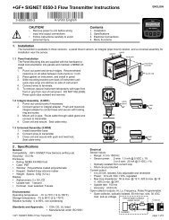
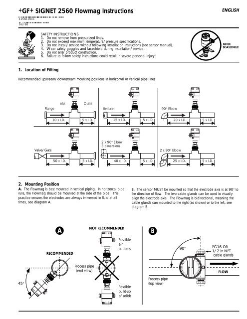
3. +GF+ SIGNET FittingsTypeDescriptionTypeDescriptionPlastic tees• 0.5 to 4 in. male & female versions• PVC or CPVC• Mounts via glue-on fittingsMetric plastic saddle• For pipes DN 65 to 100• Requires a 30 mm diam. hole in the pipe• Wedge and saddle arrows must matchMetric wafer fitting• For pipes DN 65 to 100• Follow the recommended installation guidelinesPVC glue-onsaddles(O-ring notrequired)• 2 to 4 in., cut 1-7/16 in. hole in pipe• Align wedge arrows with saddle arrows during assembly.• <strong>Flow</strong>mag not compatible with fittings over 4 inch.Metric union fitting• For pipes from DN 15 to 50• PP or PVDF• Follow the recommended installation guidelines4. Installation1. Lubricate the sensor O-rings with a silicone lubricant (e.g. GEsilicone compound #G632 or equivalent). DO NOT use anypetroleum based lubricant that will attack the O-rings.FLOW<strong>Flow</strong>directiondecal2. Grasp the metal sensor nut in hand and use an alternating/twistingmotion to insert the sensor body into the fitting. Caution! Becareful not to bump the sensor nosepiece. Excessive force on thesensor nosepiece will damage the sensor.3. Verify the flow direction arrow decal on the <strong>Flow</strong>mag casing ispointing in the direction of flow, turn casing to align.Yellow fitting capHand tighten only!FLOWMetal sensor nutLubricateO-ringsFitting4. The sensor electrode axis MUST be mounted at 90° to thedirection of flow. The two cable glands can be used to visuallyalign the electrode axis. The <strong>Flow</strong>mag is bidirectional, meaningthe cable glands can be mounted to the left (as shown in the sideview) or to the right (as shown in the top view).Pipeline (side view)FLOW5. After establishing electrode alignment (step 5), Hand tighten theyellow fitting cap until the sensor flange bottoms against thefitting flange.Pipeline (top view)90°CableglandsWARNING!Damage will result to the yellow fitting cap threads and/orfitting threads if hand tools of any kind are used.<strong>2560</strong> (top)SAFETY INSTRUCTIONS1. Do not remove from pressurized lines.2. Do not exceed maximum temperature/pressure specifications.3. Do not install/service without following installation instructions (see sensor manual).4. Wear safety goggles and faceshield during installation/service.5. Do not alter product construction.6. Failure to follow safety instructions could result in severe personal injury!NEVERDISASSEMBLE!
5. Mounting DetailsThe following steps must be observed to ensure optimum operation andIP66/NEMA 4X watertight protection:• Housing gaskets must be clean and undamaged.• The housing cover must be tightened firmly.• The cables used for connection must have an outer diameter of7 to 12 mm (0.275 to 0.475 in.).• Shielded cable should always be used for maximum noise immunity• The cable glands must be firmly tightened.• The cable must loop downward before entering the cable glandto prevent moisture from seeping into the casing.• An unused cable gland must be replaced with a blind plug(customer supplied). Cable ports are offered with PG16 or1/2 in. NPT threads.• The protective bush inside the cable gland should not be removed.Cable glandtightenedWith moisturedrip loopCable glandnot tightenedWithout moisturedrip loop6. WiringCAUTION!Never install, wire up or dismantle the instrumentwhen power is applied. Always observe both polarity andoperating voltage before applying power.1. To reduce the possibility of AC noise interference, separate ACpower and/or relay lines from the current output lines. Seediagram A for wiring details.2. Use only 7 to 12 mm (0.275 to 0.475) diameter cable in cableglands to ensure a watertight seal.3. The <strong>Flow</strong>mag's casing terminal MUST be connected to earthground to ensure complete electromagnetic compatibility andmaximum performance, see diagram B.A+-System power:20 to 30 VDC1 2 23 24 25 26 27Relay output:75 VDC @ 0.5 A max.60 VAC @ 0.4 A max.+-124 20<strong>Flow</strong>+GF+ SIGNETCurrent output:4 to 20 mALoad R L =750 Ω max.+GF+SIGNET50914. Observe the mounting details outlined in section 6 after makingconnections to ensure maximum watertight IP66/NEMA 4Xprotection.BEarth ground terminal4 mm 2 (11 AWG)Copper wirePipeline(end view)
7. Calibration1. Set miniature switch 1 (test mode) to the "normal" position (sec. 9.2).2. Set the miniature switches 2 to 4 as appropriate (sec. 8.2):• Time constant & relay latch time• Relay function• Min./max. fail-safe setting3. After switching on the power supply, the outputs are deactivated for 5s (relay de-energized and current output remains at 0 mA). Both LEDsflash during this procedure.4. Set the full-scale value. This can be done one of two ways (sec 8.2):Full-scale value with actual flow (local calibration)• Take into account general flow rates anticipated.• Turn the full-scale potentiometer until the green LED lights up.Setting the full-scale value without actual flow• Set the full-scale potentiometer at the mean anticipated flow rate.5. Use the limit switch to set the relay switch point in % of the preset full-scale setting described in step 4.8. Operation Details8.1 Operation and display surfacesLimit value setting as a percentageof the set full scale (sec. 8.2)Red LED for limit value or errorindicationTest mode (sw #1)Setupcheckboxes1 2 3 4 100limiterror ≤ 20mAlimits %235010145m/s1 2 3 4normal t=3s limit mintestt=10s limit max+ errortime switch fail safe75VDC/0,5A 4-20mA20...30VDC 670VAC/0,4A R L max.750Ω+ -L+ L-1 2 23 24 25 26 27Green LED for full-scalesettingFull-scale setting(sec. 8.2)Current output timeconstant and relaylatch time (sw #2)Relay function(sw #3)Min./max fail-safe (sw. #4)Note: Customer settings can be recorded in the checkboxes printed on the display panel for future reference.8.2 Operation functions and display elementsOperating and display element(factory settings)Description of function2t = 3st = 10sTime constant & relay latch timeThe times t = 3 s and t = 10 s correspond to the current output time constant and also to the relaylatch time. When t = 3 s is selected, the relay switches when the flow signal exceeds eithermaximum or minimum fail-safe setting and remains in this state for 3 seconds. When t = 10 s isselected, the relay switches after the flow signal exceeds either minimum or maximum fail-safesetting for 10 seconds, then remains in this state for an additional 10 seconds. While the relay isswitched "latched", changes in the flow rate are not taken into account.
Operation functions and display elements continued...Operating and display element(factory setting)Description of function3limitlimit+ errorRelay functionsThe relay is energized if all functions are operating correctly. The relay is de-energizedimmediately when an error or alarm occurs.• Limit: The relay de-energizes and the red LED lights up if the signal moves outside the upperor lower limit value (depending on the min./max. fail-safe setting).• Limit + error: The same function as for "limit", and additionally: The relay de-energizes if theflow rate is larger than 5 m/s (15 ft/s) or if an instrument error occurs. The red LED flashes."Error" has higher priority than "limit".4min.max.Min./max. fail-safe setting• Maximum fail-safe: The relay de-energizes if the signal rises above the limit value.• Minimum fail-safe: The relay de-energizes and the red LED lights if the signal falls below thelimit value setting.1234PotentiometerFull-scale settingThe full-scale potentiometer can be set to any value within the 1 to 5 m/s (3 to 15 ft/s) operationrange.m/s5• Turning the potentiometer: The transition from off to a lighted green LED shows agreementbetween the momentary flow velocity and the set full scale value, at which the current outputwill be set to 20 mA.Green LEDGreen LED• Lit:The flow rate is smaller than the set full-scale value (i.e. I =
9.2 Checking the electronicsThe <strong>Flow</strong>mag can be verified with an internal test mode as follows:1normaltestTest mode1. Set test mode switch number 1 to the "test" position.2. Turn the full-scale potentiometer counterclockwise until it comes to the mechanical stop.The measured current output must be exactly 20 mA at this time.1234Potentiometer3. If the current output (step 2) is not 20 mA, the electronics module must be replaced.m/s510. SpecificationsGeneralOperating range:Full scale range:Conductivity:Accuracy:Repeatability:Enclosure rating:Housing material:0.1 to 7 m/s (0.3 to 20 ft/s)1 to 5 m/s (3 to 15 ft/s) recommended≥20 µS/cm±2% of range with local calibration at flowvelocities >1 m/s (3 ft/s)±2% of rangeIP66/NEMA 4XAluminum, epoxy powder coatedElectricalPower supply:Power consumption:Current output:20 to 30 VDC (24 VDC nominal)
Dimensions:150 mm (5.9 in.) 99 mm (3.9 in.)86 mm(3.4 in.)16 mm (0.6 in.)PG16 OR1/2 in. NPTcable glandports (2)66 mm (2.6 in.)178 mm (7.0 in.)75 mm (3.0 in.)44 mm(1.7 in.)93 mm (3.7 in.)244 mm (9.6 in.)34 mm(1.3 in.)83 mm (3.3 in.)34 mm(1.3 in.)40 mm(1.6 in.)86 mm (3.4 in.)25 mm (1 in.)19 mm (0.7 in.)22 mm (0.9 in.)NOTES:
+GF+ SIGNETSales Offices:USA <strong>Georg</strong>e <strong>Fischer</strong>, Inc., 2882 Dow Avenue, Tustin, CA 92780/USA, Tel. (714) 731-8800, Fax (714) 731-6201Switzerland <strong>Georg</strong> <strong>Fischer</strong> Rohrleitungssysteme AG, P.O. Box 671, CH-8201 Schaffhausen/Switzerland, Tel. 052/631 1111, Fax 052/631 2830Singapore <strong>Georg</strong>e <strong>Fischer</strong> Pte. Ltd., 15 Kaki Bukit Road 2, KB Warehouse Complex, Singapore 1441, Tel. 65/747 0611, Fax 65/747 0577Japan Kubota <strong>Georg</strong>e <strong>Fischer</strong>, 2-47 Shikitsuhigashi, 1-Chome, Naniwa-Ku, Osaka, 556-91 Japan, Tel. 816/648 2545, Fax 816/648 2565China <strong>Georg</strong> <strong>Fischer</strong> Ltd., Rm 1503, Business Residence Bldg. of Asia Plaza, 2-3 Bldg. No. 5th Qu Anzhenxili, Chaoyang Qu, Beijing 100029,P.R. China, Tel. 86/10 6443 0577, Fax 86/10 6443 0578Australia <strong>Georg</strong>e <strong>Fischer</strong> Pty. Ltd., Suite 3, 41 Stamford Road, Oakleigh, Victoria 3166, Australia, Tel. 61/3 9568 0966, Fax 61/3 9568 0988Signet Scientific Company, 3401 Aerojet Avenue, El Monte, CA 91731-2882 U.S.A., Tel. (626) 571-2770, Fax (626) 573-2057GEORGE FISCHER +GF+ Piping SystemsPRINTED ON RECYCLED PAPER3-<strong>2560</strong>.090-1/(B-6/98), English © Signet Scientific Company 1997 Printed in U.S.A.