Keyence LS-7000 series Laser Micrometers - Cincinnati Automation
Keyence LS-7000 series Laser Micrometers - Cincinnati Automation
Keyence LS-7000 series Laser Micrometers - Cincinnati Automation

Create successful ePaper yourself
Turn your PDF publications into a flip-book with our unique Google optimized e-Paper software.
NEW<br />
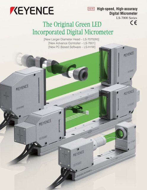
The Original Green LED<br />
Incorporated Digital Micrometer<br />
[New Larger Diameter Head – <strong>LS</strong>-7070(M)]<br />
[New Advance Controller – <strong>LS</strong>-7601]<br />
[New PC Based Software – <strong>LS</strong>-H1W]<br />
High-speed, High-accuracy<br />
Digital Micrometer<br />
<strong>LS</strong>-<strong>7000</strong> Series
Optical System Achieving High-speed, High-accuracy, and High-durability<br />
Speed, accuracy, and durability have been improved by advanced optical technology, using high-intensity Green LED, a telecentric lens,<br />
and the HL-CCD in the receiver.<br />
<strong>LS</strong>-<strong>7000</strong> Series<br />
CMOS monitor camera HL-CCD Telecentric optical system<br />
Extremely compact<br />
CMOS camera captures<br />
a realistic image of the<br />
measurement point.<br />
The specifically designed<br />
CCD achieves high speed<br />
and improved accuracy.<br />
The system allows only a parallel<br />
light to form an image, ensuring<br />
accurate measurement.<br />
The <strong>LS</strong>-<strong>7000</strong> Series features an<br />
optical system with a green LED a<br />
telecentric lens a HL-CCD.<br />
Helping achieve double speed<br />
and accuracy compared to<br />
conventional micrometers. The<br />
motor-less structure and<br />
longer-life light source ensure<br />
excellent durability that retains<br />
reliable operation for a long time.<br />
Collimator lens and<br />
special diffusion unit<br />
This optical unit distributes<br />
Green GaN LED light as a<br />
uniform beam.<br />
■ Principle diagram of the <strong>LS</strong>-<strong>7000</strong> Series<br />
CMOS monitor Telecentric optical<br />
camera system<br />
Receiver<br />
Beam splitter<br />
HL-CCD<br />
Target<br />
High-intensity GaN green LED<br />
Special diffusion unit<br />
Collimator lens<br />
High-intensity GaN Green LED<br />
The measuring head features a gallium<br />
nitride (GaN) green LED that provides a<br />
short wavelength and reliable operation.<br />
Transmitter<br />
The green LED<br />
light is distributed<br />
as a uniform,<br />
parallel light and<br />
is applied to a<br />
target. The edge<br />
between the bright<br />
and dark area on<br />
the CCD is<br />
detected as a<br />
measured value,<br />
such as an outer<br />
diameter.<br />
Conventional laser-scanning method<br />
Light-receiving element<br />
Polygon mirror<br />
Motor<br />
The laser beam is projected onto a<br />
rotating polygon mirror, the reflected<br />
light scans the measurement range,<br />
then reaches the receiving element.<br />
To improve speed and accuracy the<br />
motor would need to rotate at a<br />
faster rate at the cost of durability<br />
and reliability.<br />
■ Principle diagram of laser-scanning method<br />
Receiver lens Collimator lens (Fθ lens)<br />
Light-receiving<br />
element<br />
Reflective mirror<br />
Receiver<br />
Edge detection<br />
Target<br />
Motor<br />
Semiconductor<br />
laser<br />
Polygon mirror<br />
Light-receiving element Transmitter<br />
(for synchronization)<br />
A measured<br />
value such as an<br />
outer diameter is<br />
determined by<br />
measuring the<br />
difference in the<br />
timing between<br />
bright and dark<br />
areas created by<br />
the scanned<br />
laser beam.<br />
2
High performance achieved by Green LED<br />
The original Green LED technology achieves both quick and accurate<br />
measurement reliably and durably. Moreover, the built-in CMOS monitor<br />
camera enhances usability.<br />
Double the conventional ability<br />
High-speed & High-accuracy<br />
2400 samples/second, 0.002 Mil (±0.06<br />
μm) repeatability<br />
The continuous exposure<br />
measurement using HL-CCD<br />
enables high-speed sampling,<br />
which doubles the conventional<br />
speed and accuracy. Unlike the<br />
laser scanning method, there is no<br />
void in detection. This allows for<br />
wider applications that require<br />
more precision due to finer product<br />
designs, or faster line speed due<br />
to shorter manufacturing times.<br />
■ Measurement with continuous<br />
exposure by CCD<br />
Average<br />
D0<br />
value<br />
D1<br />
Exposure<br />
D2<br />
Fast-moving<br />
time<br />
Average<br />
value<br />
target<br />
Measured<br />
value<br />
D0 D1 D2<br />
The measurement uses the average value<br />
within the exposure time. Even an<br />
instantaneous change can be detected reliably.<br />
■ Measurement by laser-scanning<br />
method<br />
Scan line<br />
Void in detection<br />
D0<br />
Fast-moving<br />
target<br />
Measured<br />
value<br />
D0<br />
D2<br />
D2<br />
A change that occurs between the<br />
laser scan paths cannot be detected.<br />
Best in its class<br />
High-durability CCD without moving parts & Long-life LED<br />
The laser scan method was<br />
reviewed thoroughly. Resulting in<br />
the combination of Green LED and<br />
HL-CCD that solved the problem of<br />
motor durability, which had been<br />
the weak point of the<br />
laser-scanning method.<br />
Furthermore, the long-life LED<br />
achieved continued reliability over<br />
the long term.<br />
HL-CCD<br />
Green LED<br />
First in industry<br />
Visible measurement point Controller with Target Viewer<br />
The CMOS monitor camera built<br />
into the measuring head captures<br />
the image of a target, which is<br />
displayed on the LCD monitor.<br />
Since the measurement condition<br />
is visible, target positioning and<br />
measurement condition check<br />
become easier. The measurement<br />
area of the current measurement<br />
mode is indicated in real time.<br />
Outerdiameter<br />
measurement<br />
Measurement<br />
line<br />
Measurement point display<br />
function<br />
High-Accuracy CCD <strong>Micrometers</strong><br />
<strong>LS</strong>-<strong>7000</strong> Series<br />
NEW<br />
<strong>LS</strong>-7070M<br />
Large-diameter type<br />
<strong>LS</strong>-7030M<br />
Standard type<br />
<strong>LS</strong>-7010M<br />
Small-diameter type<br />
NEW<br />
<strong>LS</strong>-7601<br />
High-performance controller<br />
3
head line-up<br />
Different head variations selectable for a wide variety of applications<br />
Wide measuring range while maintaining high accuracy<br />
Large-diameter type<br />
Fully compatible<br />
<strong>LS</strong>-7070M (with monitor function)<br />
<strong>LS</strong>-7070 (without monitor function)<br />
Measuring range<br />
Smallest detectable object<br />
Measurement accuracy<br />
Repeatability<br />
0.02" to 2.56"<br />
0.5 to 65 mm<br />
0.02"<br />
0.5 mm<br />
±0.12 Mil<br />
±3 μm<br />
±0.008 Mil<br />
±0.2 μm<br />
NEW<br />
NEW<br />
2.56"<br />
65 mm<br />
Standard model achieving high speed and high accuracy<br />
Standard type<br />
Fully compatible<br />
<strong>LS</strong>-7030M (with monitor function)<br />
<strong>LS</strong>-7030 (without monitor function)<br />
Measuring range<br />
Smallest detectable object<br />
Measurement accuracy<br />
Repeatability<br />
0.01" to 1.18"<br />
0.3 to 30 mm<br />
0.01"<br />
0.3 mm<br />
±0.08 Mil<br />
±2 μm<br />
±0.006 Mil<br />
±0.15 μm<br />
1.18"<br />
30 mm<br />
More precise measurement for minute targets<br />
Small-diameter type<br />
Fully compatible<br />
<strong>LS</strong>-7010M (with monitor function)<br />
<strong>LS</strong>-7010 (without monitor function)<br />
0.24"<br />
6 mm<br />
Measuring range<br />
Smallest detectable object<br />
Measurement accuracy<br />
Repeatability<br />
0.002" to 0.24"<br />
0.04 to 6 mm<br />
0.002"<br />
0.04 mm<br />
±0.02 Mil<br />
±0.5 μm<br />
±0.002 Mil<br />
±0.06 μm<br />
Fully compatible<br />
The measuring head and<br />
controller can be connected<br />
even when they have a<br />
different measuring range<br />
or serial Nos. This allows<br />
easy maintenance and<br />
ensures reliability for an<br />
abrupt change in<br />
specifications.<br />
For harsh environments<br />
Air purge unit (Optional) & IP64 Rating<br />
Air duct<br />
Air purge<br />
unit<br />
Air purge unit (Optional)<br />
OP-79428 [for <strong>LS</strong>-7030(M)]<br />
OP-79429 [for <strong>LS</strong>-7070 (M)]<br />
NEW<br />
NEW<br />
Attaching the air purge unit in<br />
front of the measuring head and<br />
feeding an air flow prevents dirt<br />
or dust from accumulating on the<br />
head surface.<br />
The measuring head<br />
conforms to the<br />
IP64 environmental<br />
resistance standard.<br />
Water or dust<br />
intrusion into the<br />
measuring head can<br />
be reliably prevented.<br />
4
application<br />
Variety of measuring functions which support numerous inspections<br />
Dual-head mode<br />
Newly-developed<br />
[Measuring the outer diameter of a honeycomb filter]<br />
This simple, special mode measures large diameter targets or<br />
wide sheet materials. Complicated calculations or other<br />
settings are unnecessary.<br />
One-head simultaneous measurement<br />
[Measuring both the outer diameter and eccentricity of a copy roller simultaneously]<br />
One measuring head allows simultaneous measurement using<br />
two measurement modes, such as measuring the outer<br />
diameter and eccentricity.<br />
Measuring area designation<br />
[Measuring IC lead pitch]<br />
The measuring area can be designated according to the<br />
inspection purpose, such as measurement of the IC lead gap<br />
or pitch.<br />
Measuring<br />
range<br />
1.18"<br />
30 mm<br />
Lead outer dimension 1 Lead outer dimension 2<br />
Transparent object measurement<br />
[Checking the width or edge position of a glass plate]<br />
Even transparent objects that were difficult to detect with<br />
conventional micrometers can be measured. The edge detection<br />
level can be easily changed via the controller.<br />
Change in received light intensity<br />
caused by the edge of a glass<br />
object<br />
Threshold value<br />
Before threshold value adjustment<br />
Gap between leads<br />
Lead pitch<br />
Threshold value<br />
After threshold value adjustment<br />
Trend display<br />
[Measuring the outer diameter of a fiber]<br />
Data logging<br />
[Backtrack unacceptable values & history]<br />
The <strong>LS</strong>-<strong>7000</strong> Series measures the outer diameter of a fiber<br />
continuously and displays not only numeral values but also a<br />
trend graph that represents the measured values in a waveform.<br />
The history of unacceptable values, such as date/time,<br />
measured value, and comparison result, can be recorded in<br />
the internal memory of the controller.<br />
5
controller<br />
High-performance controller for ultimate usability<br />
NEW<br />
<strong>LS</strong>-7601<br />
High-performance controller<br />
LCD monitor makes viewing and aligning targets easy<br />
By offering advance functions the controller improves efficiency and<br />
meets demanding measurement needs.<br />
Easy adjustment with Target Viewer<br />
The measuring head incorporates a CMOS camera to capture an image of a<br />
target. By viewing the real-time image on the target viewer, the measurement<br />
position of a target with a complicated shape can be easily adjusted. It is<br />
also easy to check the measurement condition of a minute or transparent<br />
target.<br />
2-channel connection & Multiple I/O<br />
The compact controller measuring only one-quarter of conventional<br />
models allows connection of two sets of scanning heads. This<br />
enables simultaneous measurement and comparison. Various<br />
interfaces are also featured, including RS-232C input/output, 2<br />
channel BCD output, 2 channel I/O, and 2 channel analog output.<br />
Measurement point<br />
display function<br />
Measurement<br />
line<br />
Gap measurement<br />
Outerdiameter<br />
measurement<br />
* Screen sample for “Measuring IC lead<br />
pitch” on page 5.<br />
RS-232C<br />
I/O(ch2), BCD<br />
Analog 2-channel<br />
2 channels for<br />
measuring<br />
head connection<br />
I/O(ch1)<br />
■ Various functions<br />
Self-timing function<br />
The controller starts<br />
synchronization automatically<br />
and performs predefined<br />
measurement when a target<br />
enters the optical axis.<br />
Abnormal value ignore function<br />
This function ignores abnormal<br />
values exceeding a preset value<br />
to prevent malfunctions caused<br />
by dust or other irrelevant<br />
factors.<br />
24 types of computation functions<br />
The controller is complete with<br />
24 types of computation<br />
functions that make the most of<br />
the 2-head and 2-channel output.<br />
A controller with digital<br />
switch-like keys is also<br />
available.<br />
<strong>LS</strong>-7001<br />
Auto-zero/offset function<br />
The measured value can be<br />
reset to “0” by using a master<br />
target, or it can be set to a<br />
reference value for master<br />
adjustment.<br />
Calibration function<br />
This function makes it possible to<br />
calibrate measuring values using<br />
actual reference targets or to<br />
calibrate values theoretically.<br />
16 selectable programs<br />
Up to 16 programs including the<br />
measuring area and tolerance<br />
can be stored in the memory for<br />
each target.<br />
6
NEW<br />
Setting support software<br />
<strong>LS</strong>-Navigator<br />
<strong>LS</strong>-H1W<br />
PC<br />
Convenient operation and setup with a computer connection<br />
Using the RS-232C port a PC can be connected.<br />
You can control the <strong>LS</strong>-<strong>7000</strong> Series from configuration to data management.<br />
Easy setting/Setting data backup function<br />
The controller settings can be stored and backed up in the PC. The<br />
measurement condition setting can also be configured or changed<br />
on the PC and transferred to the controller. The setting is easy by<br />
just selecting menus with the aid of illustrations and explanation.<br />
Logging function<br />
The setting data can be transferred directly to Excel in real time.<br />
There is also a function to display the measured values on the PC<br />
screen, enabling traceability management or the preparation of<br />
quality data reports.<br />
Excel is a registered trademark<br />
of Microsoft Corporation<br />
in the U.S.A.<br />
■ Flexible installation styles according to applications<br />
Stand-alone<br />
The controller can be used as a stand-alone<br />
instrument. With the optional stand<br />
(sold separately).<br />
Panel-mounting<br />
The compact controller measures only<br />
one-quarter the size of conventional models,<br />
and can be mounted neatly in a control panel.<br />
AC power<br />
supply stand<br />
<strong>LS</strong>-S11<br />
7
Specifications<br />
■ Measuring head (Large-diameter type/Standard type)<br />
Type<br />
Category<br />
Model<br />
Measuring range<br />
Smallest detectable object<br />
Transmitter/receiver distance<br />
Light source<br />
CCD scanning range<br />
Measurement accuracy<br />
Repeatability<br />
No. of samples 7.<br />
Monitor camera<br />
Enclosure rating 8.<br />
Ambient temperature<br />
Relative humidity<br />
Weight<br />
Large-diameter<br />
with monitor camera<br />
without monitor camera<br />
<strong>LS</strong>-7070M<br />
0.02" to 2.56" 0.5 to 65 mm<br />
0.02" 0.5 mm<br />
9.84"±1.97" 250±50 mm<br />
GaN green LED<br />
Approx. 2.72" 69 mm<br />
±0.12 Mil ±3 μm 1.<br />
±0.008 Mil ±0.2 μm 2.<br />
2400 samples/sec.<br />
Provided<br />
Not provided<br />
IP64<br />
32 to 122°F (0 to +50°C)<br />
35 to 85% (No condensation)<br />
Transmitter: Approx. 540 g<br />
Transmitter: Approx. 540 g<br />
Receiver : Approx. 770 g<br />
Base : Approx. 660 g<br />
with monitor camera<br />
Standard<br />
0.01" to 1.18" 0.3 to 30 mm<br />
0.01" 0.3 mm<br />
6.30"±1.57" 160±40 mm<br />
GaN green LED<br />
Approx. 1.30" 33 mm<br />
±0.08 Mil ±2 μm 3.<br />
without monitor camera<br />
<strong>LS</strong>-7070 <strong>LS</strong>-7030M <strong>LS</strong>-7030<br />
Receiver : Approx. 730 g<br />
Base : Approx. 660 g<br />
±0.006 Mil ±0.15 μm 4.<br />
2400 samples/sec.<br />
Provided<br />
Not provided<br />
IP64<br />
32 to 122°F (0 to +50°C)<br />
35 to 85% (No condensation)<br />
Transmitter: Approx. 420 g<br />
Receiver : Approx. 570 g<br />
Base : Approx. 430 g<br />
Transmitter: Approx. 420 g<br />
Receiver : Approx. 470 g<br />
Base : Approx. 430 g<br />
■ Measuring head (Small-diameter type)<br />
Type<br />
Category<br />
Model<br />
Measuring range<br />
Smallest detectable object<br />
Transmitter/receiver distance<br />
Light source<br />
CCD scanning range<br />
Measurement accuracy<br />
Repeatability<br />
No. of samples 7.<br />
Monitor camera<br />
Enclosure rating 8.<br />
Ambient temperature<br />
Relative humidity<br />
Weight<br />
Small-diameter<br />
with monitor camera<br />
without monitor camera<br />
<strong>LS</strong>-7010M<br />
<strong>LS</strong>-7010<br />
0.002" to 0.24" 0.04 to 6 mm<br />
0.002" 0.04 mm<br />
2.36"±0.20" 60±5 mm<br />
GaN green LED<br />
Approx. 0.28" 7 mm<br />
±0.02 Mil ±0.5 μm 5.<br />
±0.002 Mil ±0.06 μm 6.<br />
2400 samples/sec.<br />
Provided<br />
Not provided<br />
IP64<br />
32 to 122°F (0 to +50°C)<br />
35 to 85% (No condensation)<br />
Transmitter: Approx. 140 g<br />
Receiver : Approx. 380 g<br />
Base : Approx. 220 g<br />
Transmitter: Approx. 140 g<br />
Receiver : Approx. 340 g<br />
Base : Approx. 220 g<br />
1. The error when a moving rod 0.79" (20 mm) in diameter is measured<br />
within the measuring area of 0.79" x 1.57" (20 x 40 mm).<br />
2. The value of ±2σ when the outer diameter of a rod 0.79" (20 mm) in<br />
diameter is measured at the center of the measuring area while the<br />
number of averaging measurements is set to 512.<br />
3. The error when a moving rod 0.39" (10 mm) in diameter is measured<br />
within the measuring area of 0.39" x 0.79" (10 x 20 mm).<br />
4. The value of ±2σ when the outer diameter of a rod 0.39" (10 mm) in<br />
diameter is measured at the center of the measuring area while the<br />
number of averaging measurements is set to 512.<br />
5. The error when a moving rod 0.04" (1 mm) in diameter is measured<br />
within the measuring area of 0.08" x 0.16" (2 x 4 mm).<br />
6. The value of ±2σ when the outer diameter of a rod 0.04" (1 mm) in<br />
diameter is measured at the center of the measuring area while the<br />
number of averaging measurements is set to 512.<br />
7. 1200 samples/sec. when the mutual interference prevention function is<br />
used.<br />
8. The connector section is excluded.<br />
Peripheral equipment<br />
Air purge unit<br />
OP-79428<br />
[For <strong>LS</strong>-7030(M)]<br />
Air purge unit<br />
OP-79429<br />
[For <strong>LS</strong>-7070(M)]<br />
AC power supply stand<br />
<strong>LS</strong>-S11<br />
Model<br />
Applicable controller<br />
Rating<br />
Environmental<br />
resistance<br />
Weight<br />
Power supply voltage<br />
Current consumption<br />
Ambient temperature<br />
Relative humidity<br />
<strong>LS</strong>-S11<br />
<strong>LS</strong>-<strong>7000</strong>/<strong>LS</strong>-7600<br />
100 to 240 VAC ±10% 50/60 Hz<br />
110 VA max.<br />
32 to 104°F (0 to +40°C)<br />
35 to 85% (No condensation)<br />
Approx. 1.7 kg<br />
Extension cables<br />
Cable between the controller and<br />
measuring head<br />
Model<br />
Cable length<br />
Weight<br />
<strong>LS</strong>-C3A<br />
9.8' 3 m<br />
Approx. 250 g<br />
<strong>LS</strong>-C10A<br />
32.8' 10 m<br />
Approx. 700 g<br />
<strong>LS</strong>-C30A<br />
98.4' 30 m<br />
Approx. 2,000 g<br />
* Up to two cables are connectable, provided that the total length is a<br />
maximum of 131.2' (40 m).<br />
Cable between the receiver and transmitter<br />
Model<br />
Cable length<br />
Weight<br />
OP-42182<br />
3.3' 1 m<br />
Approx. 50 g<br />
OP-42183<br />
9.8' 3 m<br />
Approx. 120 g<br />
* Up to two cables are connectable, provided that the<br />
total length is a maximum of 19.7' (6 m).<br />
Camera cable<br />
Model<br />
Cable length<br />
Weight<br />
<strong>LS</strong>-C3AM<br />
9.8' 3 m<br />
Approx. 150 g<br />
<strong>LS</strong>-C10AM<br />
32.8' 10 m<br />
Approx. 450 g<br />
<strong>LS</strong>-C30AM<br />
98.4' 30 m<br />
Approx. 1,250 g<br />
* Up to two cables are connectable, provided that the total length is a<br />
maximum of 131.2' (40 m).<br />
8
■ Controller<br />
Type<br />
Model<br />
No. of connectable measuring heads<br />
Minimum display unit<br />
Display range<br />
Measurement position monitor<br />
Tolerance check output display<br />
Alarm output<br />
5-level comparator output<br />
Comparator ready output<br />
Strobe output<br />
Synchronous input<br />
Reset input<br />
Auto-zero input<br />
Program selection input<br />
Statistical processing input<br />
Analog output<br />
5-level comparator output<br />
Comparator ready output<br />
SUB mode 1. Strobe output<br />
Statistical processing output<br />
Function output<br />
BCD output<br />
BCD mode 1.<br />
BCD selection output<br />
BCD selection input<br />
Synchronous input<br />
Reset input<br />
Auto-zero input<br />
Statistical processing input<br />
RS-232C interface<br />
Video output<br />
Display<br />
Terminal block<br />
Connector I/O<br />
Major functions<br />
Rating 2.<br />
Environmental<br />
resistance<br />
Weight<br />
Measurement display<br />
Power supply voltage<br />
Current consumption<br />
Enclosure rating<br />
Ambient temperature<br />
Relative humidity<br />
1. Either SUB mode or BCD mode can be selected.<br />
2. AC power supply can be used when the <strong>LS</strong>-S1 (AC power supply stand) is connected.<br />
High-performance<br />
<strong>LS</strong>-7601<br />
2 (fully compatible for all head types)<br />
TFT 5.5-inch LCD display,<br />
Backlight: CCFL (Average life: 40,000 hours)<br />
Standard<br />
<strong>LS</strong>-7001<br />
2 (fully compatible for all head types except monitor (M) models)<br />
Main display: 7-segment red LED (Character height: 0.80" 20.3 mm)<br />
Sub-display: 7-segment red LED (Character height: 0.39" 9.9 mm) x 3<br />
0.0004 to 3.9 Mil 0.01 to 100 μm (7-level selectable)<br />
±99.99999 to ±9999.9 mm (Linked to minimum display unit setting, mm/ μm selectable)<br />
Monitor image (When the measuring head with the monitor function is connected.)<br />
7-level display with a red LED<br />
5-level LCD indicator<br />
Green LED (GO), Red LED x 2 (HI, LO)<br />
NPN open-collector output (N.C.)<br />
Non-voltage input x 4 inputs<br />
Non-voltage input for OUT1 —<br />
±10 V x 2 outputs<br />
NPN open-collector output x 2 outputs<br />
Selectable from focus, area check, and differential, NPN open-collector output x 2 outputs<br />
Measurement data output (Sign + 7 digits), OUT1/OUT2 selectable, NPN open-collector output<br />
NPN open-collector output<br />
Non-voltage input<br />
Non-voltage input for OUT2<br />
—<br />
Measurement data output and control I/O, printer (Baud rate can be selected up to 115200 bps.)<br />
Conforming to the NTSC system (PIN connector)<br />
—<br />
Simultaneous measurement, Area designation, Calculation,<br />
Averaging, Calibration, 16-program memory, Measurement modes,<br />
Auto-zero, Print-out, Abnormal value elimination, Transparent object<br />
measurement, Measurement point display, Group comparison,<br />
Unacceptable value history, Trend display, Statistical processing,<br />
Mutual interference prevention, Application function, etc.<br />
1.2 A max.<br />
Approx. 1,010 g<br />
The rating of the NPN open-collector inside the terminal block is: 100 mA max. (40 V max.), residual voltage of 0.5 V max.<br />
The rating of the NPN open-collector inside the connector I/O is: 30 mA max. (30 V max.), residual voltage of 0.5 V max.<br />
The rating of non-voltage input is: ON voltage of 1 V max., OFF current of 0.6 mA max.<br />
NPN open-collector output for OUT1<br />
Non-voltage input for OUT1<br />
NPN open-collector output for OUT2<br />
Non-voltage input for OUT2<br />
24 VDC ±10%<br />
IP64 (Panel surface only)<br />
32 to 104°F (0 to +40°C)<br />
35 to 85%, (No condensation)<br />
—<br />
Simultaneous measurement, Area designation, Calculation,<br />
Averaging, Calibration, 16-program memory, Measurement modes,<br />
Auto-zero, Print-out, Abnormal value elimination, Transparent object<br />
measurement, Mutual interference prevention, etc.<br />
0.7 A max.<br />
Approx. 820 g<br />
■ System environment for using the <strong>LS</strong>-Navigator Setting Support Software<br />
Model<br />
CPU<br />
Applicable OS<br />
Memory capacity<br />
Display<br />
Free space in hard disk<br />
Interface<br />
Excel<br />
<strong>LS</strong>-H1W<br />
Pentium III 400 MHz or higher<br />
Windows XP Professional Edition /Home Edition<br />
Windows 2000 Professional<br />
64 MB or more<br />
VGA (800 x 600 pixels) or more, 256 colors or more<br />
10 MB or more<br />
RS-232C (serial port) or USB to RS-232C converter (OP-51643) interface required<br />
Excel 2003/2002/2000<br />
■ CE Marking<br />
The <strong>LS</strong>-<strong>7000</strong> Series complies with the following European standards:<br />
EMC Directive: EN61326-1<br />
Low-voltage directive: EN60825-1 (LED class 1)/EN61010-1<br />
(Installation category II, Pollution degree 2)<br />
Windows XP Professional Edition/Home Edition, Windows 2000 Professional, Excel 2003/2002/2000 are<br />
registered trademarks of Microsoft Corporation in the U.S.A.<br />
9
Dimensions<br />
Measuring head <strong>LS</strong>-7070 (<strong>LS</strong>-7070M)<br />
0.35" 9<br />
1.18"<br />
30<br />
4 x M2.5, Effective depth: 0.20" 5<br />
Unit : inch mm<br />
1.18" 0.35"<br />
30 9<br />
4 x M2.5, Effective depth: 0.20" 5<br />
2.76"<br />
70<br />
4 x ø0.22" ø5.5, through-hole<br />
ø0.37" ø9.5 spot facing, d=0.22" 5.5<br />
0.59"0.59"<br />
15 15<br />
4 x M4, Effective depth: 0.39" 10<br />
2.76"<br />
70<br />
0.83" 21<br />
Measuring<br />
head<br />
1.65"<br />
42<br />
1.10" 28<br />
0.83" 21<br />
Front surface of receiver 0.94"±0.01"<br />
24±0.3 Measurement position<br />
4.53"<br />
115<br />
1.02" 26<br />
2.56"<br />
65<br />
0.26" 6.5<br />
Front surface of transmitter<br />
3 x ø0.22" ø5.5 (mounting hole)<br />
5.12"<br />
130<br />
Measuring area<br />
4.49"<br />
114<br />
4.09"<br />
104<br />
3.64"<br />
92.5<br />
2.20"±0.01"<br />
56±0.3<br />
2.56"<br />
65<br />
3.64"<br />
92.5 4.09"<br />
104<br />
0.22" 5.5<br />
0.79" 20<br />
* [Cable length: 19.69" 500]<br />
Cable length: 19.69" 500<br />
Cable length: 10.63" 270<br />
0.71"<br />
18<br />
2.83"<br />
72<br />
1.22"<br />
31<br />
5.91"<br />
150<br />
9.84" 250<br />
12.28" 312<br />
1.22"<br />
31<br />
0.91"<br />
23<br />
2.20"<br />
56<br />
0.22"5.5<br />
3 x ø0.22" ø5.5 (mounting hole)<br />
Cable length: 10.24" 260<br />
4 x M5, Effective depth: 0.39" 10<br />
0.22" 0.22"<br />
5.5 Base 1.61" 41<br />
5.5<br />
1.18" 30<br />
30 1.18"<br />
2 x M4, Effective depth: 0.20" 5<br />
7.87"<br />
200<br />
10.24"<br />
260<br />
17.87"<br />
454<br />
5.91"<br />
150<br />
7.64"<br />
194<br />
2 x M4, Effective depth: 0.20" 5<br />
0.83" 21<br />
0.83" 21<br />
2.36"<br />
7.36"<br />
60 187<br />
5.39" 1.73"<br />
137 44<br />
* Figures in brackets are the values for the <strong>LS</strong>-7070M.<br />
Measuring head <strong>LS</strong>-7030 (<strong>LS</strong>-7030M)<br />
0.39"10<br />
0.94" 24<br />
4 x M2.5, Effective depth: 0.12" 3<br />
4 x ø0.18" ø4.5, through-hole<br />
ø0.31" ø8 spot facing, d=0.18" 4.5<br />
0.59" ø0.59"<br />
15 15<br />
4 x M4, Effective depth: 0.39" 10<br />
0.94" 24<br />
0.39" 10<br />
4 x M2.5, Effective depth: 0.12" 3<br />
1.77" 45<br />
1.77" 45<br />
1.50" 38<br />
1.02" 26<br />
0.53"<br />
13.5<br />
Front surface<br />
of receiver<br />
0.87"±0.008" 22±0.2<br />
Measurement position<br />
4.29"<br />
(1.34") *(34)<br />
109<br />
2.17" 55<br />
Measuring area<br />
2.17" 55<br />
4.98"<br />
126.5<br />
0.24"<br />
6<br />
Front surface<br />
of transmitter<br />
0.53"<br />
13.5<br />
2.81" 2.36"<br />
71.5 60<br />
1.40"±0.008"<br />
35.5±0.2<br />
1.18" 30<br />
2.36" 2.81"<br />
60 71.5<br />
0.22"<br />
5.5<br />
3 x ø0.22" ø5.5 (mounting hole)<br />
* [Cable length: 19.69" 500]<br />
Cable length: 19.69" 500<br />
Cable length: 7.87" 200<br />
19.69"<br />
50<br />
1.06"<br />
27<br />
3.15"<br />
80<br />
6.30"<br />
160<br />
8.43"<br />
214<br />
1.06"<br />
27<br />
19.69"<br />
50<br />
0.22" 5.5<br />
0.77"19.5<br />
3 x ø0.22" ø5.5 (mounting hole)<br />
Cable length: 7.87" 200<br />
0.24" 6<br />
4 x M4 through-hole 0.24" 6<br />
1.02" 26<br />
1.02"<br />
26<br />
(1.89")(48)<br />
5.31" 135<br />
5.31" 135<br />
6.89" 175<br />
6.50" 165<br />
13.39" 340<br />
1.63" 41.5<br />
2 x M4, Effective depth: 0.20" 5 2 x M4, Effective depth: 0.20" 5<br />
0.87" 22<br />
0.87" 22<br />
1.50" 38<br />
4.45"<br />
113<br />
4.45"<br />
113<br />
1.50" 38<br />
* Figures in brackets are the values for the <strong>LS</strong>-7030M.<br />
10
Measuring head<br />
<strong>LS</strong>-7010 (<strong>LS</strong>-7010M)<br />
4 x ø0.18" ø4.5, through-hole<br />
ø0.31" ø8 spot facing, d=0.18" 4.5<br />
0.59"0.59"<br />
4 x M4 through-hole<br />
15 15<br />
Unit : inch mm<br />
Measuring head 1.42" 36<br />
0.94"24 1.02"26<br />
0.63"±0.008"<br />
0.98" 0.98"<br />
Measurement position 25 25<br />
16±0.2<br />
(8.94") (227)<br />
3 x ø0.16" ø4 (mounting hole) 2.99"<br />
Measuring<br />
76<br />
2.01" area 0.31"<br />
51 0.16" 8<br />
4<br />
2.20" 1.81"<br />
56 46<br />
0.16"4<br />
* [Cable length: 19.69" 500]<br />
Cable length: 19.69" 500<br />
Cable length: 5.51" 140<br />
0.24"<br />
6<br />
2 x M4 through-hole<br />
40 1.57"<br />
±0.2 ±0.008"<br />
0.24"<br />
6<br />
1.26"<br />
32<br />
0.24"<br />
6<br />
2 x ø0.16" ø4 (mounting hole)<br />
1.81"<br />
46 56<br />
2.20"<br />
0.16" 0.71" 18<br />
(1.18")<br />
4<br />
(30)<br />
(2.36")<br />
Cable length: 5.51" 140<br />
0.14"<br />
(60)<br />
0.14"<br />
3.5 3.19" 81<br />
1.50"<br />
38<br />
3.5<br />
1.89" 4.96" 126 0.98"<br />
48<br />
25<br />
0.18"<br />
Base1.38" 35 4.5<br />
26 1.02"<br />
4.53" 1.77"<br />
115<br />
45<br />
5.59" 142<br />
2.76"<br />
70<br />
8.35" 212<br />
2 x M4 through-hole<br />
2 x M4, Effective depth: 0.20" 5 2 x M4, Effective depth: 0.20" 5<br />
0.63" 16<br />
0.63" 16<br />
1.57"<br />
40<br />
3.62"<br />
92<br />
1.85"<br />
47 0.71"<br />
18<br />
* Figures in brackets are the values for the <strong>LS</strong>-7010M.<br />
High-performance controller <strong>LS</strong>-7601<br />
Standard controller <strong>LS</strong>-7001<br />
0.88" 22.3<br />
(7.52")<br />
(191)<br />
0.88"<br />
22.3<br />
(Outer dimension of<br />
mounting bracket)<br />
6.89" 175<br />
(Effective display<br />
area)<br />
0.98" 25<br />
0.20"5<br />
2.36"<br />
(7.52") (Outer dimension of<br />
2.36"<br />
60<br />
(191) mounting bracket)<br />
0.20" 5 60<br />
Panel thickness: 0.05 to 0.16"<br />
6.89"<br />
Panel thickness: 0.05 to 0.16"<br />
1.2 to 4.0 175<br />
1.2 to 4.0<br />
Mounting screw<br />
0.98"25<br />
Mounting screw<br />
3.27" 83<br />
(Effective<br />
display area)<br />
2.36"<br />
60 5.12"<br />
130<br />
Mounting bracket<br />
2.36"<br />
60 5.12"<br />
130<br />
Mounting bracket<br />
(2.56")<br />
(65)<br />
(2.56")<br />
(65)<br />
AC power supply stand <strong>LS</strong>-S11<br />
6.73" 171<br />
Panel cutout<br />
8.15"<br />
207<br />
6.65"<br />
169<br />
+0.04<br />
0<br />
+1<br />
0<br />
7.72"<br />
196<br />
2.36"<br />
60<br />
4.88"<br />
+0.04<br />
0<br />
124<br />
+1<br />
0<br />
7.87"<br />
200<br />
(1.38")(35)<br />
0.55"<br />
7.01" 178<br />
14<br />
1.71"<br />
43.5 5.83" 148<br />
8.50" 216<br />
7.91" 201<br />
(3.94")<br />
(100)<br />
Extension cables<br />
Cable between the controller and measuring head<br />
<strong>LS</strong>-C A<br />
0.58" 14.7<br />
1.69"<br />
43<br />
ø0.25"<br />
ø6.3<br />
1.69"<br />
43<br />
0.55"14<br />
Camera cable<br />
<strong>LS</strong>-C AM<br />
0.45"11.5<br />
1.38"<br />
35<br />
Cable between the receiver and transmitter<br />
ø0.19" 1.39"<br />
1.38"<br />
ø0.19"<br />
ø4.8 35.3<br />
35<br />
ø4.8<br />
1.39"<br />
35.3<br />
0.43" 11 0.45" 11.5<br />
0.43" 11<br />
Model Cable length Model Cable length Model Cable length<br />
<strong>LS</strong>-C3A 9.8' 3 m<br />
<strong>LS</strong>-C3AM 9.8' 3 m * Up to two cables are OP-42182 3.3' 1 m<br />
<strong>LS</strong>-C10A 32.8' 10 m * Up to two cables are connectable, <strong>LS</strong>-C10AM 32.8' 10 m connectable, provided OP-42183 9.8' 3 m<br />
provided that the total length is a<br />
that the total length is a<br />
<strong>LS</strong>-C30A 98.4' 30 m<br />
maximum of 132' (40 m).<br />
<strong>LS</strong>-C30AM 98.4' 30 m<br />
maximum of 132' (40 m).<br />
* Up to two cables are connectable,<br />
provided that the total length is a<br />
maximum of 19.80' (6 m).<br />
CAD data download service: www.keyence.com/usa.php<br />
11
Related products<br />
High-speed, High-accuracy CCD <strong>Laser</strong> Displacement Sensor<br />
LK-G Series<br />
Ultra-high speed<br />
50 kHz<br />
High accuracy<br />
±0.02%<br />
Wide measuring range<br />
0.35" to 39.37" 9 to 1000 mm<br />
Various types of measuring heads<br />
6 types<br />
■ Applications<br />
Measuring the thickness of a silicon wafer Measuring the thickness of a glass plate Measuring the runout of a disk rotor Measuring the height of a jet solder bath<br />
CALL<br />
TOLL<br />
FREE<br />
TO CONTACT YOUR LOCAL OFFICE<br />
1 - 8 8 8 - 5 3 9 - 3 6 2 3<br />
KEYENCE CORPORATION OF AMERICA<br />
Corporate Office 50 Tice Blvd., Woodcliff Lake, NJ 07677 Phone:201-930-0100 Fax:201-930-0099 E-mail:keyence@keyence.com<br />
■ Regional offices<br />
AL<br />
CA<br />
CA<br />
Birmingham<br />
N.California<br />
Los Angeles<br />
CO<br />
FL<br />
GA<br />
IL<br />
Denver<br />
Tampa<br />
Atlanta<br />
Chicago<br />
IN<br />
KS<br />
KY<br />
MA<br />
Indianapolis<br />
Kansas City<br />
Louisville<br />
Boston<br />
MI<br />
MI<br />
MN<br />
MO<br />
Detroit<br />
Grand Rapids<br />
Minneapolis<br />
St. Louis<br />
NJ<br />
NY<br />
NC<br />
NC<br />
Woodcliff Lake<br />
Rochester<br />
Charlotte<br />
Raleigh<br />
OH<br />
OH<br />
OR<br />
PA<br />
<strong>Cincinnati</strong><br />
Cleveland<br />
Portland<br />
Philadelphia<br />
Specifications are subject to change without notice.<br />
www.keyence.com<br />
Fax : 201-930-0099<br />
SC<br />
TN<br />
TN<br />
TX<br />
Greenville<br />
Nashville<br />
Knoxville<br />
Dallas<br />
VA<br />
WA<br />
Richmond<br />
Seattle<br />
KEYENCE CANADA INC.<br />
Head Office Phone:905-696-9970 Fax:905-696-8340<br />
Montreal Phone:514-694-4740 Fax:514-694-3206<br />
E-mail:keyence@keyence.com<br />
KEYENCE MEXICO S.A. DE C.V.<br />
Phone:+52-81-8220-7900 Fax:+52-81-8220-9097<br />
Email:keyencemexico@keyence.com<br />
KA1-0038<br />
© KEYENCE CORPORATION, 2008 <strong>LS</strong>76-KA-C-E 0058-3 000677 Printed in Japan