Keyence LT-9000 series high accuracy surface scanning laser
Keyence LT-9000 series high accuracy surface scanning laser
Keyence LT-9000 series high accuracy surface scanning laser

Create successful ePaper yourself
Turn your PDF publications into a flip-book with our unique Google optimized e-Paper software.
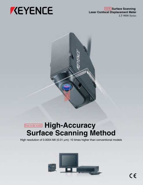
NEW Surface ScanningLaser Confocal Displacement Meter<strong>LT</strong>-<strong>9000</strong> SeriesHigh-AccuracySurface Scanning MethodFirst in the worldHigh resolution of 0.0004 Mil (0.01 µm); 10 times <strong>high</strong>er than conventional models
The <strong>high</strong>-<strong>accuracy</strong>, <strong>surface</strong> <strong>scanning</strong>method allows measurementsof all types of targetsA tuning fork unit and oscillating unit are combinedto create a <strong>surface</strong> <strong>scanning</strong> <strong>laser</strong>. This results inadvanced displacement and profile measurementsthat are unaffected by target color or angle.OUT1:A1+75.00GORUN PRG0PROFILEUP LIMIT+40.00LO LIMIT-40.00POSITIONSurface Scanning LaserConfocal Displacement Meter<strong>LT</strong>-<strong>9000</strong> SeriesA1:DIFFA2:AVEBGA profile measurementSemiconductor <strong>laser</strong>PinholeLight-receiving elementLighting LEDCCD cameraVerticalZ-axis <strong>scanning</strong>A tuning fork is combined with theconfocal principle to obtain <strong>high</strong><strong>accuracy</strong>measurement.Collimating lensObjective lensTuning fork/oscillating unitHorizontalX-axis <strong>scanning</strong>An oscillating unit creates a wide scanarea. This allows increasedmeasurement stability.2
10 times <strong>high</strong>er thanconventional modelsExcellent resolution of 0.0004 Mil(0.01 µm) for <strong>high</strong>-<strong>accuracy</strong>applicationsVerticalZ-axis <strong>scanning</strong>High-<strong>accuracy</strong> measurement method uses theconfocal principle and tuning forkThe <strong>laser</strong> beam is focused on the target <strong>surface</strong> through anobjective lens that vibrates up and down at <strong>high</strong> speed bymeans of a tuning fork. The beam reflected off the target <strong>surface</strong>is converged on a pinhole and then enters the light-receivingelement. By measuring the exact position of the objective lenswhen the light enters the light-receiving element, the targetheight can be determined. The sensor measures the distance tothe target <strong>surface</strong> accurately without being affected by thematerial, color, or angle of the target.When focus is not obtained onthe target <strong>surface</strong>When focus is obtained onthe target <strong>surface</strong>The coaxial optical system improvesmeasurement performanceHigh angular characteristicsMeasurement offilm thicknessSemiconductor<strong>laser</strong>Light-receivingelementPinholeThe receivedTuning fork light intensityis low.Semiconductor<strong>laser</strong>Light-receivingelementPinholeThe receivedTuning fork light intensityis <strong>high</strong>.SensorSensorA small amount of receivedlight passes through thepinhole.All of the received lightpasses through the pinhole.First in the worldNew wide <strong>scanning</strong> feature increasesmeasurement stability and versatilityX-axis <strong>scanning</strong>High-<strong>accuracy</strong> <strong>scanning</strong> using the oscillating unitThe 0.08 Mil (2-µm) <strong>laser</strong> beam spotcan be scanned horizontally for upto 44 Mil (1100 µm) by using the<strong>high</strong>-<strong>accuracy</strong> oscillatingmechanism. This new <strong>scanning</strong>method enables measurements ofprofile, angle, and area.HorizontalWide <strong>scanning</strong> enables various measurementsProfile measurementAngular measurementAdjustable <strong>scanning</strong> width according to the applicationThe <strong>scanning</strong> width of the <strong>laser</strong>beam can be changed freelyaccording to the application and the<strong>surface</strong> condition of the target. Inaddition, <strong>high</strong>ly stable displacementmeasurements are ensured bycalculating the <strong>scanning</strong> data.Adjusted for<strong>high</strong>-speed response0.08 Mil2 µm0.08 Mil2 µmAdjusted forstabilityMAX. 44 MilMAX. 1100 µm3
Surface Scanning Laser ConfocalDisplacement Meter<strong>LT</strong>-<strong>9000</strong>Multiple measurement modes for a wide range of applicationsSeriesProfile measurementThe <strong>surface</strong> profile can be traced accurately using the oscillating unit.NEWThe <strong>surface</strong> profile can be tracedusing the double-<strong>scanning</strong> method.The height difference between thetwo points can be measured.Measuring the profile of solder paste on a PWBOUT1:A1+75.00GOThe profile of lead-free solder can be measured for detecting abnormalities such as cracks,bridges, and insufficient soldering.RUN PRG0PROFILEUP LIMIT+40.00LO LIMIT-40.00POSITIONA1:DIFFA2:AVETransparent object thickness measurementThe <strong>surface</strong> condition, film thickness,and thickness of transparent objectscan be measured. In addition, theslant correction function enablesmore reliable measurements.Measuring the thickness of an optical discThe intermediate layer of an optical disc can bemeasured.The <strong>surface</strong> condition, film thickness, and thickness oftransparent objects can be measured stably byutilizing the confocal principle.The first<strong>surface</strong>The second<strong>surface</strong>The third<strong>surface</strong>OUT1:OUT2: +100.00+40.00[+1PMulti-<strong>surface</strong> measurementfunction NEWThe peak value of light intensity ofup to four points can be detectedwith one measurement unit. Theselected measurement <strong>surface</strong>can be measured with <strong>high</strong><strong>accuracy</strong>.RUN PRG0DISTANCE+2P]OUT1NE THICKARPKx :100PKx :105PROG : 80The first <strong>surface</strong>The second <strong>surface</strong>The third <strong>surface</strong>The fourth <strong>surface</strong>Angle measurementNEWMeasurement of a cross-sectional areaMeasuring the parallelism of aCCD and cover glassNEWMeasuring the cross-sectional areaof liquid sealing materialAn angle can be measured inincrements of 0.01 degreesbased on the measurementvalues of two or more pointsobtained by <strong>scanning</strong> the<strong>laser</strong> beam spot.The inclination of a CCD <strong>surface</strong>against the rear <strong>surface</strong> of the glasscan be measured accurately using thenewly developed relative anglemeasurement.The cross-sectional areacan be determinedbased on the crosssectional profile obtainedby <strong>scanning</strong> the <strong>laser</strong>beam spot.The profile and cross-sectional area ofsealing material applied for bondingglass substrates.5
Quick and easy setup functionsMicroscope functionEmploying a <strong>high</strong>-speed auto-focus lens for clear imagesAn ultra-compact CCD camera is incorporated in thesensor head. The target image can be enlargedapproximately 85 times* on the monitor screen. Thespecial optical design provides sharp images, allowingeasy positioning of microscopic targets.(* When using special monitor CA-MN80)IC chipImage of phoenix on a 10-yen coinMonitor for measured value and waveform displayFor real-time display of measured valuesand waveformObservations of displacement and profile data can beperformed with ease.OUT1:+20.00 GORUN PRG0PROFILEUP LIMIT+70.00OUT1:+30.00 GORUN PRG0PROFILEUP LIMIT+100.00LO LIMIT-70.00LO LIMIT-100.00POSITIONPOSITIONA1:DIFFA2:AVEA1:DIFFA2:AVESoldered area of leadsEngraved markSimplified setup menuSimple operation using special remote consoleThe special remote console and user-friendly setupmenu greatly simplify the setup process. Measurementcan begin just minutes after unpacking the box.SCAN WIDTHSCAN CENTERFINE MODE1100/2+0OFFRUN PRG0PROFILEBASICAREASCANDARKMASKSMOOTHMODEMultiple I/O options come standardNEWFor enhanced operational flexibilityAll of the necessary interfaces including 2 channels ofanalog outputs, RS-232C output, 2 channels of decisionoutputs, and binary outputs are incorporated as standardinto the compact housing.(Only half the size of conventional models.)2-channel decision output and binary outputAnalog outputRS-232C outputBinary outputLimits outputRS-232C2-channel analog output6
■ System configurationController <strong>LT</strong>-9501Remote controlconsole(Included with the <strong>LT</strong>-9501)6.56' (2-m) extension cable<strong>LT</strong>-C232.81' (10-m) extension cable<strong>LT</strong>-C10Measuring unit <strong>LT</strong>-9010MMeasuring unit <strong>LT</strong>-9030MI/O cable (9.84' (3 m))OP-42341Measuring unit mounting standOP-51543* The X-Y stageis not included.LCD color monitor CA-MN80Stand OP-42278RS-232 cableOP-96368RS-232C conversion adapterFor 25-pin OP-96369For 9-pin OP-26401■ DimensionsUnit: mm InchController<strong>LT</strong>-9501/9001, <strong>LT</strong>-9501SO(5652)/9001SO(5653)Measuring unit<strong>LT</strong>-9010M/90102.56"652.36" 60 672.64"ø6.3 Cable length: 500ø0.25 1.69"2.20"560.17"4.51776.97"2208.66"Remote controlconsole0.44"17.1 11.20.67"112.74.44"47 2.11.85" 0.08"1.13"28.80.67"17.15.50.22"ø0.79ø203.07781.93" 5.39"49 1378.27" 3.94"210(100)Cable between themeasuring unit andthe controller<strong>LT</strong>-C2/<strong>LT</strong>-C101.69"1.69"43 43150.59"331.30"1.58" 14.7 140.55"ø0.18"3 x ø4.5mountingholeø0.25 6.56', 32.81'ø6.3 Cable length: 2 m, 10 m220.87"1.81"46ø15 ø0.592.07"52.53.70"94371.46"6 ±0.5 (Reference distance)0.24 ±0.020.16" 4 ø4.5 ø0.18Cable length: 3 m9.84'LCD monitorCA-MN80(Dimensionsof 5.05"128.2mounting180 (Effectivebracket)display191.2 area)7.53"ø0.43ø119.50"241.2(Dimensions of mounting bracket)9.56"2301515.94"6.14"1566.73"170.9(Effective display area)1064.17"6340.24" 1.34"Panel thickness:1.0 to 4.0 mm0.04" 0.16"Mounting bracketMounting screw169.5 +10+0.046.67" 0Panel cutout219.5 +1 0+0.048.64" 025510.04"<strong>LT</strong>-9030M/90302058.07"ø6.3 Cable length: 500ø0.25"19.69"150.59"331.30"ø0.18"3 x ø4.5mountinghole2.56"652.20"560.18"4.51.81"46ø26.4ø1.04"220.87"2.07"52.55.32"135783.07"30 ±1 (Reference distance)1.18" ±0.04"7
NEWNew features of the <strong>LT</strong>-<strong>9000</strong> SeriesInterchangeable sensor headand controllerA CPU is built into the sensor head sothat the sensor head and controllerbecome interchangeable. Thecalibration data and other informationof the sensor head is digitallytransferred to the controller.Complicated adjustments are no longerrequired upon replacement.Calibration functionThe measured values can becalibrated by using a reference target.Since logical calibration can beperformed using numerical values,optimal adjustment can be madeaccording to the details of the actualtarget measurements.Up to 65.6' (20-m) cableextensionWiring can be extended up to 65.6' (20m) by adopting the digital method forcommunications between the controllerand sensor head. This greatlyenhances the installation flexibility.Various measurement modesThe <strong>LT</strong>-<strong>9000</strong> Series features 9 types of measurement holdmodes, including Peak hold, Bottom hold, and Peak-topeakhold mode. The mode can be set up as desiredaccording to the application without using an analogcontroller or PLC.2-channel simultaneous measurementThe measurement of two different points can be performedsimultaneously. The <strong>surface</strong> position and thickness of glasscan be measured and displayed at the same time.Measuring thewarpage of a PWBMeasuring the <strong>surface</strong>position and thickness of asheet of glass1 ch: Surface position of the glass2 ch: Thickness of the glassPeak value (Maximum value)Peak-to-peak value (Fluctuation)Surface of the glassOUT1:OUT2: +500.00+150.00RUN PRG0[M1 M2 ] DISTANCEOUT1NDISTANCEEARONTiming inputOFFMeasurement rangeBottom value (Minimum value)Rear face of the glassPKx :190PKx :190PROG :130Thickness of the glassApplications by industry■ Automotive industry ■ LCD industry ■ Print industry ■ Plastic industryMeasuring the <strong>surface</strong> profileof a brake discMeasuring the cross-sectionalarea of liquid sealing materialon LCD glassMeasuring the cell depthof a print rollMeasuring the thickness of acontact lens8
■ SpecificationsControllerModelControllerMeasuring unitMeasuring unit compatibilityDisplayTerminalblockControl I/ORS-232C interfaceVideo outputMinimum display unitDisplay rangeMicroscope functionDisplay cycle 1.Analog outputTiming input/Reset input/Auto-zero inputMonitor dedicated power supply 2.Limits mode 3. 3-step limits outputBinary outputBinary mode 3. Strobe outputBinary selection outputBinary selection inputStability outputLaser remote inputProgram change inputDistance mode 4.<strong>LT</strong>-9501/<strong>LT</strong>-9001<strong>LT</strong>-9501SO(5652)/<strong>LT</strong>-9001SO(5653)<strong>LT</strong>-9010M/<strong>LT</strong>-9010<strong>LT</strong>-9030M/<strong>LT</strong>-9030Measuring units are interchangeable without factory recalibration.0.01 µm, 1 µm 2 , 0.01° 0.01 µm±9999.99 µm, ±999999 µm 2 , ±9999.99° ±9999.99 µmAvailable (<strong>LT</strong>-9501 only)Available (<strong>LT</strong>-9501SO(5652) only)10 times/sec.±10 V x 2 outputs, output impedance: 100 ΩNon-voltage input24 VDC, 1 AFor OUT1 and OUT2, and NPN open collector outputMeasured data output (21 bits), OUT1/OUT2/PROFILE selectableNPN open collector outputNPN open collector outputNPN open collector outputNon-voltage inputNPN open collector outputNon-voltage inputNon-voltage input x 3 inputsMeasured data output and control I/O (Selectable up to baud rate 115200 bits/s.)NTSC compliant (PIN connector)Distance measurement, Transparent objectthickness measurement, Angle measurement,Relative angle measurement, Surfaceselection, Dark-out, Mask, Trend graphdisplay, and Scan width/interval changeDistance measurement,Transparent object thicknessmeasurement, Surface selection, Dark-out,Mask, Trend graph display,and Scan width/interval changeMainfunctionPower supply voltageCurrent consumptionRatingOvervoltage categoryPollution degreeAmbient temperatureRelative humidityWeight1. Varies depending on the setting2. Dedicated power supply for the monitor specified by KEYENCE.3. Select either the Limits mode or the Binary mode.4. Select either the Distance mode or the Profile mode. (Distance mode is only available with the <strong>LT</strong>-9501SO(5652)and <strong>LT</strong>-9001SO(5653).)The rating of the NPN open-collector output is 30 mA (30 V or lower) maximum, and residual voltage is 0.5 V.The rating of the Non-voltage input is ON voltage 1 V or lower, and OFF current 0.6 mA or lower.Measuring UnitTypeProfile mode 4.CommonModelMeasurement rangeReference distanceLight sourceScan width/intervalResolution 1.Linearity 1.Sampling cycle 3.WavelengthMaximum OutputClassSpot diameterTemperature characteristics(+20 to +30°C(+68 to +86°F))MicroscopefunctionAmbient lightAmbient temperatureRelative humidityWeightArea selection (Average, Maximum,Minimum, Maximum-to-minimum, Area)Area calculation, Scan width/intervalchange, Dark-out, Smoothing, Averaging,and Profile data outputLight intensity accumulation, Microscope (<strong>LT</strong>-9501, <strong>LT</strong>-9501SO(5652) only), Tolerancejudgment, 8-program registration, Calibration, Averaging, Hold modes, Auto-zero, andinterface language selectionHigh-<strong>accuracy</strong>100 to 240 VAC ±10% 50/60 Hz110 VA or lowerII20 to 35°C (32 to 95°F), No condensation35 to 85%, No condensationApprox. 2.4 kgCable between the sensor headand controller (Extension cable)ModelCable length<strong>LT</strong>-C26.56' 2 m<strong>LT</strong>-C1032.81' 10 mWeight Approx. 200g Approx. 700g* Up to 3 cables can be connected with a totalmaximum length of 65.6' (20 m).Long-range<strong>LT</strong>-9010M <strong>LT</strong>-9010 <strong>LT</strong>-9030M <strong>LT</strong>-90300.01" ±0.3 mm 0.04" ±1.0 mm0.20" 6 mm 1.18" 30 mmVisible red semiconductor <strong>laser</strong>670 nm170 µW (IEC)/3.0 µW (FDA)Class 1 (IEC)/Class IIa (FDA)Approx. 0.08 Mil ø2 µm Approx. 0.27 Mil ø7 µm0 to 42.9 Mil 0 to 1100 µm (6 steps)/0.04 to 0.39 Mil 1 to 10 µm (4 steps)0 to 21.8 Mil 0 to 560 µm (6 steps)/0.04 to 0.03 Mil 1 to 8 µm (4 steps)0.0004 Mil 0.01 µm 0.004 Mil 0.1 µm±0.5% of F.S. ±0.3% of F.S.640 µs to 356 ms (14 steps) 640 µs to 187 ms (14 steps)±0.5% of F.S. ±0.25% of F.S.Available Unavailable Available Unavailable0.05" x 0.04"0.10" x 0.08"Field of view ––1.3 mm x 1.05 mm2.5 mm x 2.0 mmIllumination light sourceInfrared LED(wavelength: 870 nm)Approx. 400gInfrared LED–(wavelength: 870 nm)Incandescent lamp/fluorescent lamp: 10000 lux max.0 to 35°C (32 to 95°F), No condensation35 to 85%, No condensationApprox. 500g1. The value when the measurement target is an mirrored <strong>surface</strong> object that is measured in displacement mode, scan width/interval 4.8 Mil (120 µm)/0.08 Mil (2 µm), and 8-times average2. The value when the FINE mode is set to OFF.3. Sampling cycle differs according to the manufacturing variation of individual measuring units.––9
■ Long-range type<strong>LT</strong>-9030MLong range type for more flexible installation■ Long range of up to 1.18" (30 mm)■ Measuring range of -0.04" to +0.04" (-1 to +1 mm)■ Smallest beam spot of 0.28 Mil (7 µm)■ Resolution of 0.004 Mil (0.1 µm)Long-rangetype<strong>LT</strong>-9030M1.18"±0.04"30 mm±1 mmHigh-<strong>accuracy</strong>type<strong>LT</strong>-9010M0.24" 6 mm±0.01" ±0.3 mmReferenceddistanceVisit us at: http://www.keyence.comGet the Latest InformationFREEE-mail NewsletterNews on New Products,Applications, Hints & Tips,Technical Guide & CD...Product IndexSensors, Machine Vision,Laser, Measurement,Safety Light Curtains,Bar CodesDownloadCatalogs, Manuals,CAD data, Programs,Examples, etc...General Catalog/GuidebookGet the product catalog,technical guidebook,CD-ROMs...Service & SupportSensor Experts answer yourrequests: Price information,Ask the Experts, and more...Specifications are subject to change without notice.To contact your local office >> call toll free: 1-888-KEYENCE1 - 8 8 8 - 5 3 9 - 3 6 2 3KEYENCE CORPORATION OF AMERICACorporate Office50 Tice Blvd., Woodcliff Lake, NJ 07677Phone:201-930-0100 Fax:201-930-0099E-mail:keyence@keyence.comArizona Phoenix: 602-225-2425California N.California: 925-225-1440Los Angeles: 562-552-9981Colorado Denver: 303-756-8301Florida Tampa: 813-998-9887Georgia Atlanta: 770-951-1958Illinois Chicago: 847-969-0453Fax numbers of regional officesIndiana Indianapolis: 317-843-2647Massachusetts Boston: 781-453-2255Michigan Michigan: 734-591-1722Minnesota Minneapolis: 952-249-9143Missouri St. Louis: 314-275-9175New Jersey New Jersey: 201-474-1481North Carolina Charlotte: 704-423-0066Ohio Cincinnati: 513-554-1229Cleveland: 216-464-7540Oregon Portland: 503-699-8400Pennsylvania Pennsylvania: 610-382-1320Tennessee Nashville: 615-986-0114Texas Texas: 972-733-6791Virginia Virginia: 804-327-9180© KEYENCE CORPORATION, 2004 <strong>LT</strong>91-KA-C-E-0050 0024-1 Printed in Japan