Keyence GT series LVDT touch probes - Cincinnati Automation
Keyence GT series LVDT touch probes - Cincinnati Automation
Keyence GT series LVDT touch probes - Cincinnati Automation
Create successful ePaper yourself
Turn your PDF publications into a flip-book with our unique Google optimized e-Paper software.
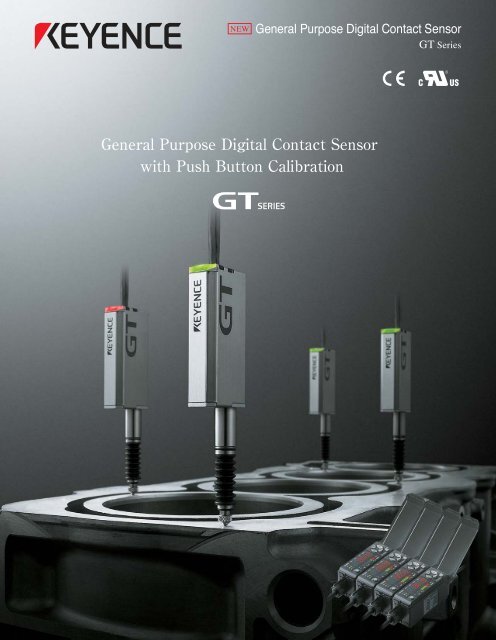
NEW<br />
General Purpose Digital Contact Sensor<br />
<strong>GT</strong> Series
sensor heads<br />
Easy set-up<br />
Compact sensor head<br />
Resolution<br />
<br />
μ<br />
Shortest in<br />
its class<br />
<br />
<br />
<br />
10 mm range<br />
<strong>GT</strong>-H10<br />
Environment resistance<br />
<br />
*Excluding low-stress types<br />
<br />
<br />
<br />
Measuring range<br />
22 mm range<br />
<strong>GT</strong>-H22<br />
amplifiers<br />
Compact amplifier<br />
<br />
<br />
DIN rail mounting<br />
amplifier unit<br />
<strong>GT</strong>-71A<br />
Panel mounting<br />
amplifier unit<br />
<strong>GT</strong>-75A
Conventional sensor head mounting is prone to short service life due to the excessive tightening force applied by<br />
a clamping fixture. Insufficient tightening in fear of damaging the head is also a problem.<br />
<br />
<br />
<br />
<br />
<br />
Tightening torque: 10 Nm<br />
Since the force is concentrated at two points,<br />
excessive tightening often damages<br />
the sensor.<br />
With the Locking collet of the <strong>GT</strong> Series<br />
the force is applied from four directions<br />
which prevents damage and product life reduction.<br />
<br />
<br />
Contact sensors are destined to break due to friction over a long period of use. The <strong>GT</strong> Series uses linear ball<br />
bearings in the spindle to achieve a longer service life.<br />
<br />
<br />
There are two types of contact sensors:<br />
those with and those without ball<br />
bearings. The use of ball bearings<br />
greatly increases the service life.<br />
<br />
<br />
The <strong>GT</strong> Series is water-resistant. This renders the structure effective for long-term use in harsh environments.
Many contact sensors typically use pulse counting methods which can miss data when targets travel at high speeds.<br />
However, <strong>Keyence</strong>'s use of the co-transformer method to keep track of the contact's absolute position eliminates<br />
skipped (missing) data.<br />
<br />
<br />
<br />
<br />
<br />
<br />
<br />
<br />
<br />
The signal level changes according to the position of the spindle inside the coil.<br />
The double-coil structure allows comparison of two signals to eliminate errors.<br />
<br />
3.54"<br />
90mm<br />
<br />
<br />
Total length<br />
3.54" (90mm)<br />
The 10-mm range<br />
head is the shortest<br />
in its class at only<br />
90 mm (3.54").<br />
secondary<br />
coil<br />
<br />
<br />
The primary coil and<br />
the secondary coil are<br />
arranged in <strong>series</strong>.<br />
Primary coil<br />
Core<br />
<br />
<br />
The detection coil<br />
and the adjustment<br />
coil sorround each<br />
other.<br />
Adjustment coil<br />
Detection coil<br />
<br />
The co-transformer method does not require troublesome adjustments.<br />
<br />
The co-transformer method and high-performance magnetic shield structure prevent mutual interference from units<br />
that are close together.
Featuring 3 digital comparator outputs (HI, LO and GO), the <strong>GT</strong> <strong>series</strong> can be lower case in minutes, not hours.<br />
Pushbutton calibration will leave you asking yourself why you hadn't switched to the <strong>GT</strong> sooner.<br />
<br />
<br />
<br />
<br />
<br />
Forget about the tedious PLC programming that you're used to with your existing <strong>LVDT</strong>'s. The <strong>GT</strong> does the work for you.<br />
In addition, you can save money by eliminating the analog I/O card from your budget.<br />
<br />
<br />
<br />
Display Analog card PLC programming<br />
<br />
<br />
<br />
<br />
<br />
Using channel select inputs on the <strong>GT</strong>-70A, users can easily toggle between up to 4 different sets of HI/LO limits. You<br />
can even use your existing HMI, while clearing out the cobwebs of PLC programming running behind the scenes.
Unlike conventional amplifiers, this amplifier does not require a large mounting space. The LED display is brighter,<br />
and easier-to-read than conventional LCD indicators.<br />
<br />
Panel mounting type<br />
amplifier<br />
<strong>GT</strong>-75A<br />
<br />
<br />
<br />
This amplifier can easily be mounted in the desired position by using a DIN-rail or the optional bracket.<br />
DIN-rail mounting type<br />
amplifier<br />
<strong>GT</strong>-71A<br />
<br />
<br />
Since the numerical display updates slower<br />
than the internal detection, you can check<br />
the status of fast moving parts easily by<br />
monitoring the bar indicator.<br />
See the status of non-defective products<br />
from bar indicator.<br />
Maintenance<br />
Maintenance<br />
Normal<br />
required<br />
required<br />
HI borderline Stable detection LO borderline<br />
<br />
<br />
<br />
Installation of expansion units enables communication<br />
between sensor heads for various calculations.<br />
<br />
Expansion units can be powered by the main unit. As a<br />
result, fewer wires need to be connected during setup,<br />
making for a quicker, neater installation.<br />
The DIN rail mounting amplifier units can<br />
be joined together by simply using the<br />
connector on the side of the unit.<br />
The panel mounting<br />
amplifier units require a flat<br />
cable for communication.<br />
<br />
<br />
Panel mounting amplifier units can be<br />
vertically mounted closely together.
The sensor head has a bright, two-color indicator. The light illuminates in red when the result is NG, which ensures<br />
easy recognition of problematic points.<br />
<br />
<br />
Operators can visually determine the state in which the products are nearing the NG limits. For example, when the<br />
height of the target is nearing the NG line, the green segments in the bar indicator decrease. Although it is difficult to<br />
recognize this state by reading numerical values, the bar indicator shows it clearly. Corrective measures can be<br />
taken before defective products are produced.<br />
<br />
<br />
<br />
<br />
<br />
The peak value of each detection can be held for an easy visual check. Since the indicator unit is separate from the<br />
detection unit, it can be mounted in any easy-to-see location.
An locking collet specifically designed for the <strong>GT</strong> Series is available, eliminating the need to prepare a clamping<br />
fixture. The sensor can be easily mounted simply by drilling a 10mm diameter hole.<br />
OP-76874<br />
Head mounting bracket A<br />
(Optional)<br />
OP-76875<br />
Head mounting bracket B<br />
(Optional)<br />
Side-mountable<br />
<br />
<br />
<br />
<br />
The amplifier is designed for simple and easy operation with the RIGHT/LEFT buttons for menu selection and the<br />
UP/DOWN buttons for value specification.<br />
<br />
<br />
<br />
<br />
Select a menu<br />
with the buttons.<br />
Specify values<br />
with the buttons.<br />
<br />
<br />
The indicator for the sensor head currently<br />
being set will blink, letting you know at a glance<br />
which of several heads is being set. (Patent<br />
pending)<br />
<br />
<br />
<br />
<br />
<br />
<br />
<br />
Unlike conventional calculations, which were done with a PLC using recorded data, calculations such as thickness<br />
and degree of flatness are automatically done by the sensor head. Simply select the proper application mode.<br />
Maximum Minimum Degree of Average Reference Twist Warpage Thickness<br />
flatness<br />
difference
Since the co-transformer method keeps track of the absolute position,<br />
the zero point position is retained even after the power is turned off. Once the zero point is adjusted,<br />
it is not necessary to adjust it again.<br />
<br />
<br />
<br />
<br />
BCD output unit<br />
DL-RB1<br />
RS-232C communication unit<br />
DL-RS1<br />
<br />
<br />
<br />
<br />
The DL-RB1 allows a PLC or other external device to read<br />
detection data for the specified amplifier.<br />
The DL-RS1 allows a PLC, PC, or other external device to<br />
read the detection or setting data for an amplifier or the<br />
calculation result of the data for several amplifiers, as well<br />
as to write setting data into an amplifier.
In the event of core<br />
damage, or contamination,<br />
the core may stick, or<br />
remain compressed. This<br />
function outputs an alarm if<br />
the core does not return to a<br />
home position. This<br />
preventive maintenance<br />
alarm helps to eliminate<br />
downtime and to minimize<br />
scrap and rework.<br />
Head does<br />
not return!<br />
Alarm<br />
output<br />
Outputs an alarm when<br />
the head cable is<br />
broken.<br />
Break!<br />
Alarm<br />
output<br />
<br />
Simply press the SET button to calibrate the unit.<br />
<br />
Setting the tolerance is as easy as pressing the SET button<br />
on a master workpiece and setting the width ( mm).<br />
<br />
Pressing the SET button once each on an OK<br />
and NG workpiece sets the detection value.<br />
HI set value<br />
LO set value<br />
HI set value<br />
LO set value<br />
SET<br />
HI set<br />
value<br />
SET<br />
SET<br />
LO set<br />
value<br />
SET<br />
SET<br />
Master<br />
workpiece<br />
NG<br />
workpiece<br />
OK<br />
workpiece<br />
OK<br />
workpiece<br />
NG<br />
workpiece<br />
<br />
<br />
When the preset timing level is exceeded, the selftiming<br />
function prepares for comparison.<br />
<br />
After the self-timing level is exceeded, the static hold<br />
function automatically detects when head oscillation<br />
has stopped and issues a comparator output.<br />
Compared with conventional sensors, this function<br />
can greatly increase tact time.(* Optional delay time can<br />
also be set as desired.)<br />
Displayed<br />
value<br />
Self-timing<br />
level<br />
<strong>GT</strong><br />
Series<br />
Conventional<br />
models<br />
0<br />
Contact with a workpiece<br />
Comparator output<br />
Time until oscillation stops<br />
Conventional delay time<br />
Time
10-mm range,<br />
Air push model<br />
sensor head<br />
<strong>GT</strong>-A10<br />
22-mm range,<br />
Air push model<br />
sensor head<br />
<strong>GT</strong>-A22<br />
<br />
<br />
Target<br />
<br />
<br />
<br />
<br />
<br />
<br />
<br />
<br />
<br />
To maintain the IP67 rating, it is<br />
necessary to attach an air tube to<br />
prevent the entry of water through the<br />
air outlet port.<br />
<br />
<br />
<br />
The speed controller (optional)<br />
allows the spindle movement<br />
speed to be adjusted.<br />
Speed controller<br />
OP-82133
The spring reduces the force<br />
applied by contact, reducing the<br />
damage potential to the target.<br />
(A fluorine plastic contact is also<br />
available.)<br />
10 mm range,<br />
low-stress sensor head<br />
<strong>GT</strong>-H10L<br />
22 mm range,<br />
low-stress sensor head<br />
<strong>GT</strong>-H22L<br />
<br />
<br />
<br />
<br />
<br />
<br />
<br />
The low-stress sensor head<br />
with a fluorine plastic<br />
contact prevents scratches<br />
on the PC board.<br />
The low-stress sensor head<br />
prevents deformation of a<br />
lightweight target.<br />
<br />
<br />
<br />
Select a contact to suit your application.<br />
Easier wiring is possible as a relay amplifier is not needed.<br />
Standard<br />
Flat plate<br />
Roller<br />
<br />
Needle Super-tough Ceramic<br />
<br />
Fluorine plastic Offset Spacer<br />
* The standard contact is factory-attached to the sensor head.
Single head<br />
Multiple heads/when additional amplifier units are installed (Application modes)<br />
STD<br />
P-H B-H P-P Maximum Minimum Degree of Average Reference Twist Warpage Thickness<br />
flatness<br />
difference<br />
Standard Peak hold Bottom hold Peak to peak<br />
<br />
Rivet height<br />
differentiation<br />
Outputs HI, GO,<br />
and LO according<br />
to rivet height.<br />
<br />
Insertion depth<br />
The self-timing<br />
function enables<br />
you to detect<br />
insertion depth<br />
without a timing<br />
input.<br />
<br />
Packing insertion<br />
check<br />
Confirms that<br />
targets are properly<br />
seated.<br />
<br />
Shaft inclination<br />
detection<br />
Ensures proper<br />
alignment.<br />
Warpage<br />
Board warpage<br />
detection<br />
Degree of<br />
flatness<br />
Confirms if<br />
workpiece warpage<br />
falls within<br />
acceptable limits.<br />
Workpiece flatness<br />
Confirms if workpiece<br />
flatness falls within<br />
acceptable limits.
Reference<br />
difference<br />
Determining pin<br />
height<br />
Checks If pin<br />
height is within the<br />
specified range of<br />
a reference<br />
surface.<br />
Twist<br />
Detecting twist<br />
Judges if<br />
workpiece twisting<br />
falls within<br />
acceptable limits.<br />
Thickness<br />
Shaft diameter<br />
measurement<br />
Reference<br />
difference<br />
Gasket number<br />
check<br />
Differentiates if the<br />
difference from the<br />
reference head is<br />
within a specified<br />
range.<br />
Input /Output Circuits<br />
I/O circuit <strong>GT</strong>-71/ 72 / 75/76<br />
External Input circuit<br />
Main circuit<br />
Main circuit<br />
Overcurrent<br />
protection circuit<br />
I/O circuit<br />
I/O circuit <strong>GT</strong>-71P/72P/75P/76P<br />
Overcurrent<br />
protection circuit<br />
Input circuit<br />
Brown*1<br />
Black (HI output)<br />
Load<br />
White (LO output)<br />
Load<br />
Gray (GOoutput)<br />
Load<br />
Blue*1<br />
Pink, purple ,Pink/purple*3<br />
Brown*1<br />
Black (HI output)<br />
White (LO output) Load<br />
Gray (GO output)<br />
Load<br />
Load<br />
Blue*1<br />
Pink, purple ,Pink/purple*3<br />
12 to 24 VDC*2<br />
5 to 40 VDC<br />
5 to 40 VDC<br />
5 to 40 VDC<br />
0 V<br />
External Input<br />
12 to 24 VDC*2<br />
0V<br />
External Input<br />
Main circuit Main circuit<br />
Pink: Preset input<br />
Purple: Bank A input<br />
Pink/purple: Bank B input/timing input switching<br />
Blue*1<br />
(Short-circuit current: 1 mA or less)<br />
External Input circuit<br />
Brown*1<br />
12 to 24 VDC<br />
Pink: Preset input<br />
Purple: Bank A input<br />
Pink/purple: Bank B input/timing input switching<br />
(Short-circuit current: 2 mA or less)<br />
*1 Brown and blue are applicable only to main units (<strong>GT</strong>-71/71P/75/75P), not to expansion units (<strong>GT</strong>-72/72P/76/76P).<br />
*2 At expansion, 12 VDC changes to 24 VDC.<br />
*3 For details on external input, see the External Input Circuit Diagram.
Product lineup<br />
■ Sensor heads<br />
■ Amplifier units<br />
Type<br />
Standard Air push models Low-stress<br />
Model<br />
<strong>GT</strong>-H10<br />
<strong>GT</strong>-H22<br />
<strong>GT</strong>-A10<br />
<strong>GT</strong>-A22<br />
<strong>GT</strong>-H10L<br />
<strong>GT</strong>-H22L<br />
Shape Measuring range<br />
Model<br />
Shape Type Output type<br />
0.39"<br />
10 mm<br />
0.87"<br />
22 mm<br />
0.39"<br />
10 mm<br />
0.87"<br />
22 mm<br />
0.39"<br />
10 mm<br />
0.87"<br />
22 mm<br />
<strong>GT</strong>-71A<br />
<strong>GT</strong>-72A<br />
<strong>GT</strong>-71AP<br />
<strong>GT</strong>-72AP<br />
<strong>GT</strong>-75A<br />
<strong>GT</strong>-76A<br />
<strong>GT</strong>-75AP<br />
<strong>GT</strong>-76AP<br />
BCD output unit/RS-232C communication unit<br />
DIN rail<br />
mounting<br />
Panel<br />
mounting<br />
Main unit<br />
Expansion unit<br />
Main unit<br />
Expansion unit<br />
Main unit<br />
Expansion unit<br />
Main unit<br />
Expansion unit<br />
Model Shape Type<br />
DL-RB1<br />
DL-RS1<br />
BCD<br />
RS-232C<br />
NPN<br />
PNP<br />
NPN<br />
PNP<br />
■ Contacts<br />
■ Optional<br />
Standard<br />
(Iducled with all heads)*<br />
OP-77678<br />
Flat plate<br />
(Optional)<br />
OP-77679<br />
Roller<br />
(Optional)<br />
OP-77680<br />
Head mounting bracket A<br />
(Optional)<br />
OP-76874<br />
Head mounting bracket B<br />
(Optional)<br />
OP-76875<br />
Panel mounting bracket<br />
(Included with panelmountable<br />
amplifier units)<br />
OP-76876<br />
Needle<br />
(Optional)<br />
OP-77681<br />
Fluorine plastic<br />
(Optional)<br />
OP-80228<br />
Super-tough<br />
(Optional)<br />
OP-77682<br />
Offset<br />
(Optional)<br />
OP-77683<br />
* The standard contact is factory-attached to the sensor head.<br />
Ceramic<br />
(Optional)<br />
OP-81970<br />
Spacer<br />
(Optional)<br />
OP-77684<br />
Fixture for fastening the<br />
DIN amplifier<br />
(Optional)<br />
OP-76877<br />
Dust boot<br />
(attached to sensor head)*<br />
OP-78041<br />
(for <strong>GT</strong>-H10/A10)<br />
End unit (2 per pack)<br />
(Optional)<br />
OP-26751<br />
* Dust boot is not included with the <strong>GT</strong>-H10L/H22L<br />
Dust boot<br />
(attached to sensor head)*<br />
OP-78042<br />
(for <strong>GT</strong>-H22/A22)<br />
Speed controller<br />
(for spindle movement adjustment)<br />
(Optional)<br />
OP-82133<br />
Specifications<br />
■ Sensor head<br />
Model<br />
Measuring range<br />
Mechanical response frequency<br />
Repeatability 1.<br />
Measuring force 2.<br />
Environmental<br />
resistance<br />
Enclosure rating<br />
Materials<br />
Weight (with 2-m cable)<br />
Ambient temperature<br />
Relative humidity<br />
<strong>GT</strong>-H10<br />
10 Hz<br />
(at ambient temperature of 73°F (23°C))<br />
When installed facing down: 1.0 N<br />
When installed sideways: 0.9 N<br />
When installed facing up: 0.8 N<br />
IP67<br />
0.39" 10 mm<br />
0.12 Mil 3 μm<br />
(at ambient temperature of 73°F (23°C))<br />
<strong>GT</strong>-H10L<br />
7 Hz<br />
(at ambient temperature of 73°F (23°C))<br />
When installed facing down: 0.3 N<br />
When installed sideways: 0.25 N<br />
When installed facing up: 0.2 N<br />
<strong>GT</strong>-H22<br />
8 Hz<br />
(at ambient temperature of 73°F (23°C))<br />
When installed facing down: 1.5 N<br />
When installed sideways: 1.4 N<br />
When installed facing up: 1.3 N<br />
0.87" 22 mm<br />
0.31 Mil 8 μm<br />
(at ambient temperature of 73°F (23°C))<br />
14 to 131°F (-10 to +55°C)<br />
35 to 85%<br />
-<br />
IP67<br />
Housing: TYPE430 Stainless steel, Indicator: Polyarylate, Dust boot 3.: NBR, Contact: TYPE304 stainless steel, Cable: PVC<br />
Approx.115 g<br />
Approx.135 g<br />
<strong>GT</strong>-H22L<br />
5 Hz<br />
(at ambient temperature of 73°F (23°C))<br />
When installed facing down: 0.35 N<br />
When installed sideways: 0.3 N<br />
When installed facing up: 0.25 N<br />
-<br />
1. Value read at the center of the measuring range with the response time set to 100 ms.<br />
2. Value read near the center of the measuring range<br />
3. Dust boot is not included with the <strong>GT</strong>-H10L/H22L<br />
Sensor head (Air push models)<br />
Model<br />
Measuring range<br />
Repeatability 1.<br />
<strong>GT</strong>-A10<br />
0.39" 10 mm<br />
0.12 Mil 3 μm<br />
(at ambient temperature of 73°F (23°C))<br />
<strong>GT</strong>-A22<br />
0.87" 22 mm<br />
0.31 Mil 8 μm<br />
(at ambient temperature of 73°F (23°C))<br />
Measuring force 2.<br />
Environmental<br />
resistance<br />
Ambient temperature<br />
Relative humidity<br />
Enclosure rating<br />
Operating pressure range<br />
Withstanding pressure<br />
Material<br />
Weight (with 2-m cable)<br />
When installed facing down: 1.0 N<br />
When installed sideways: 0.9 N<br />
When installed facing up: 0.8 N<br />
When installed facing down: 1.5 N<br />
When installed sideways: 1.4 N<br />
When installed facing up: 1.3 N<br />
32 to 131°F (0°C to +55°C)<br />
35 to 85%<br />
IP67 3.<br />
0.35 to 0.5 MPa<br />
1.0MPa<br />
Housing: TYPE430 stainless steel, Cylinder: Aluminum alloy, Plastic section of air joint: Polyacetal, Metal section of air joint: Nickel-plated brass,<br />
Indicator: Polyarylate, Dust boot: NBR, Contact: TYPE304 stainless steel, Cable: PVC<br />
Approx.150 g<br />
Approx.180 g<br />
1. Value read at the center of the measuring range at ambient temperature of 73°F(23°C) with the response time set to 100 ms.<br />
2. Value read near the center of the measuring range when the sensor head is installed downward.<br />
3. To ensure you achieve the rating, connect the air tube to the air outlet joint and prevent foreign matter from entering it through the joint.
■ Amplifier<br />
NPN<br />
Model<br />
PNP<br />
Mounting method<br />
Main unit/ Expansion unit 2.<br />
Power supply voltage 3.<br />
<strong>GT</strong>-71A<br />
<strong>GT</strong>-71AP<br />
Main unit<br />
DIN rail mount 1.<br />
<strong>GT</strong>-72A<br />
<strong>GT</strong>-72AP<br />
<strong>GT</strong>-75A<br />
<strong>GT</strong>-75AP<br />
Expansion unit<br />
Main unit<br />
12 to 24 VDC, ripple (P-P) 10% or less<br />
Panel mount<br />
<strong>GT</strong>-76A<br />
<strong>GT</strong>-76AP<br />
Expansion unit<br />
Power consumption<br />
Normal<br />
Power saving (eco)<br />
At 12 V<br />
1140 mW (95 mA) or less<br />
600 mW (50 mA) or less<br />
At 24 V<br />
1200 mW (50 mA) or less<br />
840 mW (35 mA) or less<br />
Display method<br />
Display range<br />
Display resolution<br />
Sampling rate<br />
Main functions<br />
Timing input<br />
Control input Preset input<br />
Bank input<br />
HIGH, GO, LOW output<br />
Response time<br />
Environmental<br />
resistance<br />
Materials<br />
Weight<br />
Accessories<br />
Measured value display<br />
Other displays<br />
Ambient temperature<br />
Relative humidity<br />
Vibration<br />
6-digit 7-segment LED (red)<br />
2-color 13-level bar LED display (red, green), indicators (red, green)<br />
-99.999 to 999.999<br />
0.039Mil 1 μm<br />
2000 times/second<br />
Preset, Hold, Variable hysteresis, Variable response time, Multiplier setting, Bank function (4 banks),<br />
Self-timing, Power save (eco) mode, Application mode, Calibration function, Core alarm<br />
Non-voltage input (relay contact, solid state), input time: 2 ms or more<br />
Non-voltage input (relay contact, solid state), input time: 20 ms or more<br />
NPN (PNP) open collector, 50 mA max. (NPN: 40 V or less, PNP: 30 V or less), residual voltage: 1 V or less, N.O./N.C. switchable<br />
hsp (1.5 ms) , 5 ms, 10 ms, 100 ms, 500 ms, 1 s, 5 s<br />
14 to 131°F (-10 to +55°C)<br />
35 to 85% (No condensation)<br />
10 to 55 Hz, double amplitude: 1.5 mm, 2 hours in each of X, Y, and Z directions<br />
Main body case: Polycarbonate, Key top: Polyacetal, Front sheet: Polycarbonate, Cable: PVC<br />
<strong>GT</strong>-71A(P), <strong>GT</strong>-72A(P): Approx. 110 g (including the power cable)<br />
<strong>GT</strong>-75A(P), <strong>GT</strong>-76A(P): Approx 110 g (including panel mounting bracket, protective front cover, power cable)<br />
<strong>GT</strong>-71A(P), <strong>GT</strong>-72A(P): instruction manual<br />
<strong>GT</strong>-75A(P): Panel mounting bracket, protective front cover, power cable, instruction manual<br />
<strong>GT</strong>-76A(P): Panel mounting bracket, protective front cover, power cable, flat cable for expansion, instruction manual<br />
1. Be sure to mount the DIN rail mounting amplifier on a DIN rail (i.e. the unit should be mounted on the metal DIN plate itself).<br />
For additional amplifier unit installation, be sure to use the end unit (OP-26751).<br />
2. One main unit and nine expansion units (ten in total) can be additionally installed.<br />
For additional amplifier unit installation, each output current must be 20 mA or less.<br />
3. If additional amplifier units are installed, the power supply voltage is 24 VDC.<br />
Communication unit (common specifications)<br />
Model<br />
DL-RB1<br />
DL-RS1<br />
Type<br />
BCD<br />
RS-232C<br />
Power supply voltage<br />
24 VDC Ripple (P-P) 10% max. (supplied from the connected amplifier)<br />
Current consumption<br />
20 mA max.<br />
18 mA max.<br />
No. of connectable amplifiers<br />
10 units max. (including the main unit)<br />
Indicator<br />
Environmental<br />
resistance<br />
Material<br />
Weight<br />
Accessory<br />
Ambient temperature<br />
Relative humidity<br />
Vibration<br />
Alarm indicator (Red),<br />
Power indicator (Green)<br />
Communication status indicator (Green x 2),<br />
Alarm indicator (Red),<br />
Power indicator (Green)<br />
14 to 131°F (-10 to +55°C)<br />
35 to 85%<br />
10 to 55 Hz, double amplitude: 1.5 mm, 2 hours each in the X, Y and Z axis<br />
Housing: Polycarbonate<br />
Approx. 46 g<br />
Approx. 53 g<br />
Instruction manual, End unit (2 pcs.),<br />
Switch protection sticker, Expansion connector cover<br />
Communication unit (Communication specifications of DL-RS1)<br />
Model<br />
Communication method<br />
Synchronization<br />
Transmission code<br />
Baud rate<br />
Data length<br />
Parity check<br />
Stop bit length<br />
Delimiter<br />
DL-RS1<br />
Full duplex<br />
Start-stop<br />
ASCII<br />
Selectable from 2400, 4800, 9600, 19200, 38400 bps<br />
(Factory setting: 9600 bps)<br />
Selectable from 7 bits or 8 bits<br />
(Factory setting: 8 bits)<br />
Selectable from none, even, odd<br />
(Factory setting: None)<br />
1 bit<br />
Receive: CR or CR+LF (Automatically recognized)<br />
Send: CR+LF (Fixed)<br />
*Only amplifiers with a model name suffixed with an A can be connected.<br />
Pin assignment of DL-RB1 (BCD output)<br />
I/O circuit diagram
Dimensions<br />
Unit : inch mm<br />
Sensor head<br />
0.39" 10 mm range <strong>GT</strong>-H10<br />
Air push models sensor head<br />
0.39" 10 mm range <strong>GT</strong>-A10<br />
Low-stress sensor head<br />
0.39" 10 mm range <strong>GT</strong>-H10L<br />
2x¿0.10" ¿2.5<br />
2-core shielded<br />
Cable length(6.6' 2m)<br />
0.88"<br />
22.4<br />
0.47"<br />
12<br />
2x¿0.10" ¿2.5<br />
2-core shielded<br />
Cable length(6.6' 2m)<br />
0.88"<br />
22.4<br />
Quick-connect joint for air inlet<br />
(for air tube with 0.16" 4-mm outer diameter)<br />
Quick-connect joint for air outlet<br />
(for air tube with 0.10" 2.5-mm inner diameter)<br />
2x¿0.10" ¿2.5<br />
2-core shielded<br />
Cable length(6.6' 2m)<br />
0.88"<br />
22.4<br />
0.47"<br />
12<br />
1.89"<br />
48<br />
1.89"<br />
48<br />
0.55"<br />
*1 *1<br />
14<br />
30.2 1.19" 26.4 1.04"<br />
to to<br />
41.7 1.64" 37.9 1.49"<br />
0.15"<br />
3.8<br />
0.24"<br />
6<br />
(0.65")<br />
(16.4)<br />
¿0.31" ¿8<br />
+0<br />
h5 (-0.0002")<br />
+0<br />
-0.006<br />
( )<br />
¿0.16"<br />
¿4<br />
*1 *1<br />
30.6 1.21" 26.8 1.01"<br />
to to<br />
41.7 1.64" 37.9 1.49"<br />
1.89"<br />
48<br />
0.55"14<br />
0.47"<br />
12<br />
(4.28")<br />
(108.7)<br />
0.48" 0.06" 1.4<br />
12.1<br />
0.71" 18.15<br />
1.71"<br />
43.4<br />
*1 *1<br />
30.2 1.19"<br />
to<br />
41.7 1.64"<br />
26.4 1.04"<br />
to<br />
37.9 1.49"<br />
0.15"<br />
3.8<br />
0.55"<br />
14<br />
0.24"<br />
6<br />
(0.65")<br />
(16.4)<br />
¿0.31" ¿8<br />
+0<br />
-0.0002"<br />
+0<br />
-0.006<br />
h5 ( )<br />
( )<br />
¿0.16"<br />
¿4<br />
0.24"<br />
0.15" 6<br />
3.8<br />
(0.65")<br />
(16.4)<br />
¿0.31" ¿8<br />
+0<br />
-0.0002"<br />
+0<br />
-0.006<br />
h5 ( )<br />
( )<br />
¿0.16" ¿4<br />
0.24" 6<br />
0.47" 12<br />
0.87" 22 mm range <strong>GT</strong>-H22<br />
0.87" 22 mm range <strong>GT</strong>-A22<br />
0.87" 22 mm range <strong>GT</strong>-H22L<br />
2x¿0.10" ¿2.5<br />
2-core shielded<br />
Cable length(6.6' 2m)<br />
0.88"<br />
22.4<br />
0.47"<br />
12<br />
2x¿0.10" ¿2.5<br />
2-core shielded<br />
Cable length(6.6' 2m)<br />
0.88"<br />
22.4<br />
Quick-connect joint for air inlet<br />
(for air tube with 0.16" 4-mm outer diameter)<br />
Quick-connect joint for air outlet<br />
(for air tube with 0.10" 2.5-mm inner diameter)<br />
2x¿0.10" ¿2.5<br />
2-core shielded<br />
Cable length(6.6' 2m)<br />
0.88"<br />
22.4<br />
0.47"<br />
12<br />
2.83"<br />
72<br />
0.47"<br />
12<br />
2.83"<br />
72<br />
0.75"<br />
19<br />
*1 *1<br />
40.3 1.59" 36.5 1.44"<br />
to to<br />
64.8 2.55" 61 2.40"<br />
0.15"<br />
3.8<br />
0.24"<br />
6<br />
(0.65")<br />
(16.4)<br />
¿0.31" ¿8<br />
+0<br />
h5 (-0.0002")<br />
+0<br />
h5 (-0.006<br />
)<br />
*1 These values indicate the movable range.<br />
The sensor head cable cannot be cut or extended.<br />
¿0.16"<br />
¿4<br />
*1 *1<br />
41.1 1.62" 37.3 1.47"<br />
to<br />
to<br />
64.8 2.55" 61 2.40"<br />
0.15"<br />
3.8<br />
2.83"<br />
72<br />
0.75" 19<br />
0.24"<br />
6<br />
(0.65")<br />
(16.4)<br />
¿0.31" ¿8<br />
+0<br />
-0.0002"<br />
+0<br />
-0.006<br />
h5 ( )<br />
( )<br />
0.48"<br />
12.1<br />
0.24" 6<br />
0.06" 1.4<br />
0.71" 18.15<br />
¿0.16" ¿4<br />
(5.37")<br />
(136.5)<br />
2.19"<br />
55.7<br />
0.47" 12<br />
*1 *1<br />
40.3 1.59"<br />
to<br />
64.8 2.55"<br />
36.5 1.44"<br />
to<br />
61 2.40"<br />
0.15"<br />
3.8<br />
0.75"<br />
19<br />
0.24"<br />
6<br />
(0.65")<br />
(16.4)<br />
¿0.31" ¿8<br />
+0<br />
-0.0002"<br />
+0<br />
-0.006<br />
h5 ( )<br />
( )<br />
¿0.16"<br />
¿4<br />
*1 These values indicate the movable range.<br />
The sensor head cable cannot be cut or extended.<br />
*1 These values indicate the movable range.<br />
The sensor head cable cannot be cut or extended.<br />
Head mounting bracket A OP-76874 (Optional)<br />
¿0.39" ¿10<br />
+0.0002"<br />
G6( +0.0006" )<br />
+0.005<br />
G6( +0.014 )<br />
C0.06"<br />
C1.5<br />
0.47" 0.47"<br />
12 12 R0.26"<br />
R6.5<br />
¿0.31" ¿8<br />
+0.001"<br />
G6( +0.0002" )<br />
+0.027<br />
+0.005<br />
0.14"<br />
3.5<br />
( ) +0.001"<br />
+0.0002"<br />
+0.027<br />
( )<br />
6 0.24" 0.64"<br />
7.8 0.31" 16.3<br />
Mounting hole<br />
C0.02" to C0.04"<br />
C0.5 to C1.0<br />
¿0.39" ¿10<br />
G8( )<br />
+0.005<br />
0.22" to 0.44"<br />
5.5 to 11.3<br />
0.64"<br />
16.3<br />
Head mounting bracket B<br />
OP-76875 (Optional)<br />
0.41"<br />
10.5<br />
(0.008")<br />
(0.2)<br />
0.43"<br />
11<br />
0.25"<br />
6.3<br />
R0.15"<br />
R3.8<br />
1.26"32<br />
12.1<br />
0.59"<br />
15<br />
R0.31"<br />
R8<br />
0.26"<br />
6.5 C0.08"<br />
4xC2<br />
¿0.17"<br />
¿4.2<br />
0.14"<br />
3.5<br />
Dust boot<br />
(Included)<br />
OP-78041<br />
(for <strong>GT</strong>-H10/A22)<br />
0.86"<br />
21.8<br />
¿0.30"<br />
¿7.6<br />
Material:NBR,<br />
TYPE304 stainless steel<br />
Dust boot<br />
(Included)<br />
OP-78042<br />
(for <strong>GT</strong>-H22/A22)<br />
1.57"<br />
40<br />
¿0.30"<br />
¿7.6<br />
0.26"<br />
6.5<br />
Speed controller<br />
(Optional)<br />
OP-82133<br />
0.80"<br />
20.4<br />
0.55"<br />
14<br />
¿0.13"<br />
2-¿3.2<br />
0.59"<br />
14.9 ¿0.41"<br />
0.80" ¿10.5<br />
20.4<br />
¿0.16"<br />
2-¿4<br />
0.43"<br />
11<br />
0.76" 1.13"<br />
19.4 28.6<br />
0.26"<br />
6.5<br />
Material:TYPE304 stainless steel<br />
¿0.31" ¿8<br />
+0.0006"<br />
+0.0002"<br />
+0.014<br />
G6( )( +0.005 )<br />
Material:NBR,<br />
TYPE304 stainless steel<br />
Material:NBR,<br />
stainless steel,POM,Brass,PBT,Aluminum<br />
Material:TYPE304 stainless steel, Zinc
Contact<br />
Standard<br />
(Included with all<br />
heads)* 3<br />
OP-77678<br />
0.15" 3.8<br />
0.20" 5<br />
¿0.20" ¿5<br />
SR 0.06" 1.5<br />
M 2.5 x 0.02" 0.45<br />
Material:TYPE304 stainless steel,TYPE440C stainless steel<br />
*3 The standard-type contact is attached to a head<br />
when shipped.<br />
Flat plate<br />
(Optional)<br />
OP-77679<br />
0.18"<br />
4.5<br />
0.20" 5<br />
¿0.28"<br />
¿7<br />
¿0.24"<br />
¿6<br />
Material:TYPE304 stainless steel<br />
Super-tough tungsten alloy<br />
0.35"<br />
0.17" 0.16" 9<br />
4.4 4<br />
Roller<br />
(Optional)<br />
OP-77680<br />
0.18" 4.5<br />
¿0.35"<br />
¿9<br />
0.30" 7.5<br />
0.14"<br />
0.37" 9.5 3.5<br />
¿0.30"<br />
¿7.5<br />
¿0.35"<br />
¿9<br />
Material:TYPE304 stainless steel<br />
TYPE440C stainless steel<br />
M 2.5 x 0.02" 0.45<br />
Needle<br />
(Optional)<br />
OP-77681<br />
0.83"<br />
21<br />
0.24"<br />
6.2<br />
¿0.16"¿4<br />
¿0.05" ¿1.2<br />
C0.008"<br />
C 0.2<br />
M 2.5 x 0.02" 0.45<br />
0.20" 5<br />
Material:TYPE304 stainless steel<br />
Super-tough tungsten alloy<br />
Super-tough<br />
(Optional)<br />
OP-77682<br />
0.15" 3.8<br />
0.20" 5<br />
¿0.20" ¿5<br />
SR0.06" 1.5<br />
M 2.5 x 0.02" 0.45<br />
Material:TYPE304 stainless steel<br />
Super-tough tungsten alloy<br />
Ceramic<br />
(Optional)<br />
<br />
0.15"<br />
3.8<br />
¿0.20" ¿5<br />
SR 0.06" 1.5<br />
Fluorine plastic contact<br />
(Optional)<br />
<br />
¿0.20" ¿5<br />
0.35"<br />
9<br />
SR 0.06" 1.5<br />
Offset<br />
(Optional)<br />
OP-77683<br />
¿0.06"<br />
¿1.6<br />
SR0.03" 0.8<br />
0.79"<br />
20<br />
5 0.20"<br />
0.39"<br />
10<br />
0.14"<br />
3.5<br />
Spacer<br />
(Optional)<br />
OP-77684<br />
0.14"<br />
3.6<br />
12.2 0.48"<br />
0.08"2<br />
¿0.16" ¿4<br />
M2.5 x 0.02" 0.45<br />
Effective screw depth:0.26" 6.5<br />
0.20"<br />
5<br />
M 2.5 x 0.02" 0.45<br />
Material:SUS304,Ceramic<br />
0.20"<br />
5<br />
M 2.5 x 0.02" 0.45<br />
Material: Fluorine plastic (PTFE)<br />
8 0.31"<br />
¿0.24"<br />
M 2.5 x 0.02" 0.45<br />
¿6 ¿0.30"¿7.5<br />
Material:TYPE304 stainless steel,Super-tough tungsten alloy<br />
0.22"<br />
5.5<br />
Material:TYPE304 stainless steel<br />
M 2.5 x 0.02" 0.45<br />
Amplifier unit (DIN rail mount)<br />
<strong>GT</strong>-71A/ 71AP<br />
24 0.94"<br />
15 0.59"<br />
max.135¡<br />
1.46"<br />
1.65"<br />
37<br />
42<br />
18 0.71"<br />
min. 0.49"<br />
0.59" 12.4<br />
15<br />
0.12"<br />
3<br />
0.83"<br />
21.1<br />
Amplifier unit (Panel mount)<br />
<strong>GT</strong>-75A/ 75AP/ 76A/76AP<br />
1.76"<br />
44.7 0.64"<br />
16.3<br />
*4 0.49" 12.5<br />
1.39"<br />
35.4<br />
2.76" 70<br />
2.04"<br />
51.8<br />
0.27"<br />
6.8<br />
0.46"<br />
11.6<br />
<strong>GT</strong>-72A/ 72AP<br />
0.94"<br />
24<br />
0.59"15<br />
0.12"<br />
3<br />
X<br />
11.6 0.46"<br />
1.77"45<br />
0.20"<br />
5<br />
X=0.94" x (A-0.04")+0.83"<br />
X=24 x (A-1)+21<br />
When A amplifier units<br />
are closely mounted<br />
2.48" 63 min.<br />
0.59" 2x¿0.13" ¿3.4<br />
15<br />
(0.17" x 0.13")<br />
2x(4.4 x 3.4)<br />
(Maximum when<br />
the cover is<br />
opened)<br />
*4 3.11" 79 1.65" 1.46"<br />
0.94" 0.87"<br />
42<br />
37<br />
*4 24 22<br />
0.69" 17.6<br />
0.71" 18<br />
0.69" 17.6<br />
0.59"<br />
15<br />
min. 0.49" 0.83" 1.39"<br />
1.13"<br />
12.4 21.1 35.4<br />
28.6<br />
min.<br />
0.59"<br />
min.<br />
2.76" 70<br />
1.38"<br />
0.59"<br />
15<br />
0.59"<br />
35<br />
15<br />
15<br />
Material:TYPE304 stainless steel<br />
*4 Cable specifications<br />
(common to all amplifier units)<br />
¿0.17" ¿4.2, 8-core x<br />
Brown/Blue/Black/Gray/Pink/<br />
Pink purple/Purple/White<br />
:0.26 mm 2 Cable length:6.6' 2m<br />
(for <strong>GT</strong>-71A/ 71AP/ 75A/ 75AP)<br />
¿0.17" ¿4.2, 6-core x<br />
Black/Gray/Pink/<br />
Pink purple/Purple/White<br />
:0.26 mm 2 Cable length:6.6' 2m<br />
(for <strong>GT</strong>-72A/ 72AP/ 76A/ 76AP)<br />
Panel mounting bracket (Accessory)<br />
OP-76876<br />
1.93"49<br />
1.53"<br />
38.8<br />
0.94"<br />
24<br />
Panel cutout<br />
Fixture for fastening the<br />
DIN amplifier<br />
(Optional)<br />
OP-76877<br />
(2.87") (73)<br />
0.24" 6<br />
(0.89")<br />
(22.6)<br />
DIN-rail mounting<br />
0.82"<br />
20.8<br />
Panel mounting bracket<br />
End unit (Optional)(2 per pack)<br />
OP-26751<br />
0.36"<br />
9.2<br />
0.44"<br />
11.1<br />
1.39"<br />
35.4<br />
2.12"<br />
53.8<br />
Material: Polycarbonate, stainless steel<br />
Panel thickness:<br />
0.04" to 0.24"<br />
1to6<br />
0.06"<br />
1.6<br />
2.36"<br />
60<br />
0.09"<br />
2.3<br />
Communication unit<br />
BCD output type DL-RB1<br />
0.94"<br />
24<br />
When mounted to a DIN-rail<br />
0.89" 22.5<br />
0.26"<br />
6.6<br />
0.49"<br />
12.4<br />
min.<br />
0.59"<br />
15<br />
0.83" 21<br />
0.53"13.4<br />
0.14"<br />
3.5<br />
Protective front cover<br />
When a mounting bracket is used<br />
OP-60412 (Optional)<br />
2.44"62<br />
0.94"<br />
23.8<br />
0.42"<br />
10.7<br />
+0.02"<br />
0.83" -0<br />
+0.4<br />
21 -0<br />
Material: (Mounting bracket), polyacetal<br />
(Protective front cover) polycarbonate<br />
0.89" 22.5<br />
1.77"45<br />
As for the expansion of the panel mounting type amplifier, connecting the main<br />
and expansion units is possible only in the vertical-mounting position.<br />
When connecting the units in the horizontal-mounting position, use the main units only.<br />
RS-232C communication type <br />
When mounted to a DIN-rail<br />
When a mounting bracket is used<br />
OP-60412 (Optional)<br />
(2.28")<br />
(57.8)<br />
2.10"<br />
53.4<br />
1.46"<br />
37.1<br />
2.40"<br />
60.9<br />
2.10"<br />
53.4<br />
1.46"<br />
37.1<br />
(1.90") 1.47"<br />
(48.2) 37.2<br />
1.72"<br />
43.8<br />
2.02" 1.47"<br />
51.3 37.2<br />
1.72"<br />
43.8<br />
0.83"<br />
21.1<br />
1.39"<br />
35.4<br />
2.76" 70<br />
1.24" 0.59"<br />
31.4 15<br />
2.76" 70<br />
¿0.13"<br />
2-¿3.4<br />
0.83"<br />
21.1<br />
1.39"<br />
35.4<br />
2.76" 70<br />
1.24" 0.59"<br />
31.4 15<br />
2.76" 70<br />
¿0.13"<br />
2-¿3.4<br />
0.89" 22.5<br />
(0.17" x 0.13")<br />
2-(4.4 x 3.4)<br />
0.89"<br />
22.5<br />
(0.17" x 0.13")<br />
2-(4.4 x 3.4)<br />
0.57"<br />
15<br />
1.12"<br />
28.5<br />
1.40"<br />
35.5<br />
Material:<br />
Stainless steel<br />
0.59"<br />
15<br />
1.12"<br />
28.5<br />
1.40"<br />
35.5<br />
Material:<br />
Stainless steel
Related products<br />
High-speed, High-accuracy CCD Laser Displacement Sensor<br />
LK-G Series<br />
Ultra-high speed<br />
50 kHz<br />
High accuracy<br />
±0.02%<br />
Wide measuring range<br />
0.35" to 39.37" 9 to 1000 mm<br />
Various types of measuring heads<br />
6 types<br />
■ Applications<br />
Measuring the thickness of a silicon wafer Measuring the thickness of a glass plate Measuring the runout of a disk rotor Measuring the height of a jet solder bath<br />
Specifications are subject to change without notice.<br />
CALL<br />
TOLL<br />
FREE<br />
TO CONTACT YOUR LOCAL OFFICE<br />
1 - 8 8 8 - 5 3 9 - 3 6 2 3<br />
Fax : 201-930-0099<br />
KEYENCE CORPORATION OF AMERICA<br />
Corporate Office 50 Tice Blvd., Woodcliff Lake, NJ 07677 Phone:201-930-0100 Fax:201-930-0099 E-mail:keyence@keyence.com<br />
■ Regional offices California N.California Illinois Chicago Michigan Detroit New Jersey New Jersey Ohio Cleveland<br />
Los Angeles Indiana Indianapolis<br />
Grand Rapids North Carolina Charlotte Oregon Portland<br />
Florida Tampa Kentucky Louisville Minnesota Minneapolis<br />
Raleigh Pennsylvania Philadelphia<br />
Georgia Atlanta<br />
Massachusetts Boston Missouri St. Louis Ohio <strong>Cincinnati</strong> Tennessee Nashville<br />
Tennessee<br />
Texas<br />
Virginia<br />
Washington<br />
Knoxville<br />
Dallas<br />
Richmond<br />
Seattle<br />
KEYENCE CANADA INC.<br />
1450 Meyerside Drive, #301, Mississauga, Ontario L5T 2N5 CANADA Phone:905-696-9970 Fax:905-696-8340 E-mail:keyence@keyence.com<br />
KA1-0066<br />
© KEYENCE CORPORATION, 2006 <strong>GT</strong>-KA-C-E 0116-1 000693 Printed in Japan


