Multimax
Multimax
Multimax

Create successful ePaper yourself
Turn your PDF publications into a flip-book with our unique Google optimized e-Paper software.
The ilit alit inim voluptatet dit deliquat dunt<br />
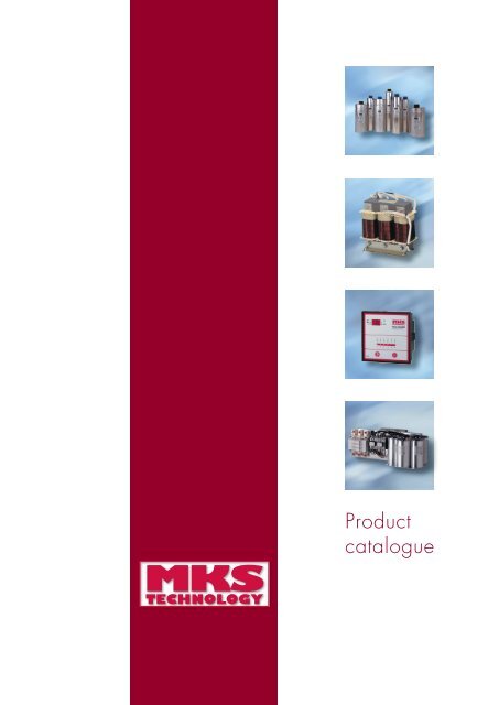
Product<br />
catalogue
MKS Technology GmbH offer reliable<br />
and innovative products and solutions<br />
in the fields of Reactive Power<br />
Compensation, Power Quality and<br />
Energy Management to customers<br />
worldwide.<br />
The founders and key personnel have<br />
over 25 years of consolidated<br />
international experience in design,<br />
development and manufacturing of<br />
Power Capacitors, reactors, Power<br />
Factor Correction Equipment,<br />
Harmonic Filters, Measuring devices<br />
and Energy Management Systems.<br />
Our innovative products are designed<br />
and built on sound engineering<br />
principles with total quality and<br />
customer satisfaction as a guiding<br />
rule.<br />
We are committed to delivering a<br />
positive value to each and every<br />
client, backed by our dedication to<br />
the highest standards of client<br />
satisfaction, reliability and integrity.<br />
After all, anything else is simply not<br />
good enough!<br />
Klaus A. Schroeder<br />
Managing Director<br />
Welcome to<br />
MKS Technology<br />
GmbH!<br />
MKS Technology GmbH<br />
manufacturing plants are<br />
strategically located in<br />
Germany, India and<br />
Singapore. Therefore we are<br />
well positioned to service<br />
our clients fast, punctually<br />
and with efficient logistics.<br />
All our products are manufactured<br />
to the highest prevailing<br />
international standards<br />
and the manufacturing<br />
locations are certified<br />
according to ISO 9001-<br />
2000.
MKS<br />
TECHNOLOGY<br />
Table of contents<br />
page<br />
Power Factor Correction Capacitors – type UHPC 02 - 6<br />
Power Factor Correction Capacitors – type HPC 07 - 11<br />
Measuring Devices – overview 12 - 13<br />
Measuring Devices – description 14 - 15<br />
Reactive Power Control Relais – description 16<br />
Reactive Power Control Relais – overview 17<br />
Reactors 18<br />
Accessories 19<br />
Measuring Devices – Network Analyser 20<br />
Maximum Demand Controller 21<br />
Power Factor Correction Equipment – Modules 22 - 23<br />
Power Factor Correction Equipment – Automatic Systems 24 - 25<br />
Software 26<br />
Notes 27 - 28<br />
1
High Performance<br />
Capacitors<br />
The HPC type Power Capacitor represents a<br />
reliable and optimized solution for Power<br />
Factor Correction.<br />
The output of these capacitors ranges from<br />
2.5 kVAr to 30 kVAr.<br />
The HPC series is a 3 Phase integrated<br />
capacitor design particularly made for Power<br />
Factor Correction in Commercial & Industrial<br />
applications.<br />
These Capacitors feature the use of a unique<br />
Metallised Polypropylene film as the dielectric<br />
to ensure a long working life with low losses.<br />
The HPC series are Self healing Capacitors,<br />
where the Electrode layer which is a special<br />
metal alloy is vacuum deposited on to the<br />
Polypropylene film dielectric.<br />
The 3 Phase Capacitor is internally composed<br />
of 3 Single Phase Capacitor windings<br />
assembled in an optimized geometric design.<br />
The electrode of the capacitor i.e.,<br />
the special Metal alloy layer is<br />
connected in parallel using a special<br />
purpose Metal Spraying technology.<br />
This special process combined with<br />
the design of the electrode enables<br />
the capacitor to have high peak<br />
current withstand levels.<br />
The Capacitor elements are<br />
processed under high vacuum to<br />
eliminate all moisture as well as to<br />
impart the correct level of thermal<br />
stability. This is an extremely critical<br />
process by which oxidation and<br />
partial discharges can be avoided<br />
during the working life of the<br />
capacitor and thus ensure better<br />
capacitance stability.<br />
The Capacitor elements are<br />
encapsulated in a special purpose<br />
synthetic material which ensures<br />
better dimensional stability and<br />
thermal conduction of heat from the<br />
insides of the capacitor.<br />
The entire capacitor assembly is<br />
housed in a extruded cylindrical<br />
aluminum case and sealed with a<br />
special double seaming technology.<br />
2
MKS<br />
TECHNOLOGY<br />
The HPC Capacitor technology features a<br />
triple safety system i.e.,<br />
• Self healing – this is a process by which<br />
the Capacitor restores itself in the event of<br />
a fault in the dielectric which can happen<br />
during high overloads, voltage transients<br />
etc.,<br />
• Pressure sensitive disconnector – this is<br />
provided in each phase of the capacitor<br />
and enables safe disconnection and<br />
electrical isolation at the end of the life of<br />
the capacitor.<br />
• Dry technology - this eliminates the risks of<br />
oil leakages which is particularly undesirable<br />
when the capacitors are used inside cabinets<br />
for Power Factor Correction.<br />
The HPC Capacitor features the use of a highly<br />
reliable two way termination design involving<br />
the use of copper and brass terminal clamps.<br />
In addition the clamping screws that are used<br />
are of large size to ensure proper torque<br />
application on the connecting cable. This<br />
terminal design has therefore a very long and<br />
reliable performance capability in comparison<br />
to conventional termination technologies.<br />
Discharge resistor modules are available in a<br />
completely integrated design which can be<br />
easily fitted on to the capacitor. The terminal<br />
of the capacitor also enables multiple capacitor<br />
units to be banked within its permissible current<br />
carrying capacity.<br />
The HPC series is therefore an optimal<br />
combination of high technology and ergonomic<br />
design which offers to the customer<br />
• Long life expectancy<br />
• Good overload capabilities<br />
• Total safety<br />
• Economic benefits due to its compact size<br />
3
3-phase, Delta Connected Capacitors<br />
Type HPC<br />
Fre- Operating Current Rated Case MKS<br />
quency Voltage at max. Capaci- Dimenisons Part Number<br />
230V 250V 280V 400V 415V 440V 480V 525V 600V 660V 690V Voltage tance in mm<br />
Hz kVar kVar kVar kVar kVar kVar kVar kVar kVar kVar kVar A µF d x h<br />
50 5.0 5.9 7.4 - - - - - - - - 15.3 3 x 100.3 75 x 285 HPC-7.4-280-3P<br />
60 6.0 7.1 8.9 - - - - - - - - 20.5<br />
50 10.0 11.8 14.8 - - - - - - - - 30.6 3 x 200.6 85 x 360 HPC-14.8-280-3P<br />
60 12.0 14.2 17.8 - - - - - - - - 41.4<br />
50 - - - 2.5 2.7 3.0 - - - - - 4.0 3 x 16.6 65 x 210 HPC-3.0-440-3P<br />
60 - - - 3.0 3.2 3.6 - - - - - 4.8<br />
50 - - - 5.0 5.4 6.1 - - - - - 7.9 3 x 33.2 65 x 210 HPC-6.1-440-3P<br />
60 - - - 6.0 6.5 7.3 - - - - - 9.5<br />
50 - - - 7.5 8.1 9.1 - - - - - 11.9 3 x 49.7 75 x 210 HPC-9.1-440-3P<br />
60 - - - 9.0 9.7 10.9 - - - - - 14.3<br />
50 - - - 12.5 13.5 15.1 - - - - - 19.8 3 x 82.9 75 x 285 HPC-15.1-440-P3<br />
60 - - - 15.0 16.1 18.2 - - - - - 23.8<br />
50 - - - 15.0 16.1 18.2 - - - - - 23.8 3 x 99.5 85 x 285 HPC-18.2-440-P3<br />
60 - - - 18.0 19.4 21.8 - - - - - 28.6<br />
50 - - - 16.7 18.0 20.2 - - - - - 26.5 3 x 110.7 85 x 285 HPC-20.2-440-P3<br />
60 - - - 20.0 21.6 24.2 - - - - - 31.8<br />
50 - - - 20.0 21.5 24.2 - - - - - 31.8 3 x 132.6 85 x 360 HPC-24.2-440-P3<br />
60 - - - 24.0 25.8 29.0 - - - - - 38.1<br />
50 - - - 23.2 25.0 28.1 - - - - - 36.8 3 x 153.9 85 x 360 HPC-28.1-440-P3<br />
60 - - - 27.8 30.0 33.7 - - - - - 44.2<br />
50 - - - 25.0 26.9 30.3 - - - - - 39.7 3 x 165.8 95 x 360 HPC-30.3-440-P3<br />
60 - - - 30.0 32.3 36.3 - - - - - 47.6<br />
50 - - - 2.5 2.7 3.0 3.6 - - - - 4.3 3 x 16.4 65 x 210 HPC-3.6-480-3P<br />
60 - - - 3.0 3.2 3.6 4.3 - - - - 5.2<br />
50 - - - 4.1 4.4 5.0 6.0 - - - - 7.2 3 x 27.4 65 x 210 HPC-6.0-480-3P<br />
60 - - - 5.0 5.3 6.0 7.1 - - - - 8.6<br />
50 - - - 5.0 5.3 6.0 7.1 - - - - 8.6 3 x 32.9 75 x 210 HPC-7.1-480-3P<br />
60 - - - 6.0 6.4 7.2 8.6 - - - - 10.3<br />
50 - - - 7.4 8.0 9.0 10.7 - - - - 12.9 3 x 49.3 75 x 285 HPC-10.7-480-P3<br />
60 - - - 8.3 8.9 10.0 11.9 - - - - 14.3<br />
50 - - - 8.3 8.9 10.0 11.9 - - - - 14.3 3 x 54.8 75 x 285 HPC-11.9-480-3P<br />
60 - - - 9.9 10.7 12.0 14.3 - - - - 17.2<br />
50 - - - 9.9 10.7 12.0 14.3 - - - - 17.2 3 x 65.8 75 x 285 HPC-14.3-480-3P<br />
60 - - - 11.9 12.8 14.4 17.1 - - - - 20.6<br />
50 - - - 12.4 13.3 15.0 17.9 - - - - 21.5 3 x 82.2 85 x 285 HPC-17.9-480-3P<br />
60 - - - 14.9 16.0 18.0 21.4 - - - - 25.8<br />
50 - - - 14.9 16.0 18.0 21.4 - - - - 25.8 3 x 98.7 85 x 285 HPC-21.4-480-3P<br />
60 - - - 17.9 19.2 21.6 25.7 - - - - 30.9<br />
50 - - - 16.5 17.8 20.0 23.8 - - - - 28.6 3 x 109.6 85 x 360 HPC-23.8-480-3P<br />
60 - - - 19.8 21.4 24.0 28.6 - - - - 34.4<br />
50 - - - 17.4 18.7 21.0 25.0 - - - - 30.1 3 x 115.1 85 x 360 HPC-25.0-480-3P<br />
60 - - - 20.8 22.4 25.2 30.0 - - - - 36.1<br />
4
MKS<br />
TECHNOLOGY<br />
Fre- Operating Current Rated Case MKS<br />
quency Voltage at max. Capaci- Dimenisons Part Number<br />
230V 250V 280V 400V 415V 440V 480V 525V 600V 660V 690V Voltage tance in mm<br />
Hz kVar kVar kVar kVar kVar kVar kVar kVar kVar kVar kVar A µF d x h<br />
50 - - - 19.8 21.4 24.0 28.6 - - - - 34.4 3 x 131.5 85 x 360 HPC-28.6-480-3P<br />
60 - - - 23.8 25.6 28.8 34.4 - - - - 41.2<br />
50 - - - 20.7 22.2 25.0 29.8 - - - - 35.8 3 x 137.0 85 x 360 HPC-29.8-480-3P<br />
60 - - - 24.8 26.7 30.0 35.7 - - - - 42.9<br />
50 - - - 22.3 24.0 27.0 32.1 - - - - 38.6 3 x 148.0 95 x 360 HPC-32.1-480-3P<br />
60 - - - 26.8 28.8 32.4 38.6 - - - - 46.4<br />
50 - - - 23.2 25.0 28.1 33.4 - - - - 40.2 3 x 154.0 95 x 360 HPC-33.4-480-3P<br />
60 - - - 27.9 30.0 33.7 40.1 - - - - 48.3<br />
50 - - - 24.8 26.7 30.0 35.7 - - - - 42.9 3 x 164.4 95 x 360 HPC-35.7-480-3P<br />
60 - - - 29.8 32.0 36.0 42.8 - - - - 51.5<br />
50 - - - 2.3 2.5 2.8 3.3 4.0 - - - 4.4 3 x 15.4 65 x 210 HPC-4.0-525-3P<br />
60 - - - 2.8 3.0 3.4 4.0 4.8 - - - 5.3<br />
50 - - - 2.9 3.1 3.5 4.2 5.0 - - - 5.5 3 x 19.2 65 x 210 HPC-5.0-525-3P<br />
60 - - - 3.5 3.7 4.2 5.0 6.0 - - - 6.6<br />
50 - - - 4.6 5.0 5.6 6.7 8.0 - - - 8.8 3 x 30.8 75 x 210 HPC-8.0-525-3P<br />
60 - - - 5.6 6.0 6.7 8.0 9.6 - - - 10.6<br />
50 - - - 5.8 6.2 7.0 8.4 10.0 - - - 11.0 3 x 38.5 75 x 285 HPC-10.0-525-3P<br />
60 - - - 7.0 7.5 8.4 10.0 12.0 - - - 13.2<br />
50 - - - 7.5 8.1 9.1 10.9 13.0 - - - 14.3 3 x 50.0 75 x 285 HPC-13.0-525-3P<br />
60 - - - 9.1 9.7 11.0 13.0 15.6 - - - 17.2<br />
50 - - - 8.7 9.4 10.5 12.5 15.0 - - - 16.5 3 x 57.7 85 x 285 HPC-15.0-525-3P<br />
60 - - - 10.4 11.2 12.6 15.0 18.0 - - - 19.8<br />
50 - - - 9.9 10.6 11.9 14.2 17.0 - - - 18.7 3 x 65.4 85 x 285 HPC-17.0-525-3P<br />
60 - - - 11.8 12.7 14.3 17.1 20.4 - - - 22.4<br />
50 - - - 11.6 12.5 14.0 16.7 20.0 - - - 22.0 3 x 77.0 85 x 285 HPC-20.0-525-3P<br />
60 - - - 13.9 15.0 16.9 20.1 24.0 - - - 26.4<br />
50 - - - 12.2 13.1 14.8 17.6 21.0 - - - 23.1 3 x 80.8 85 x 360 HPC-21.0-525-3P<br />
60 - - - 14.6 15.7 17.7 21.1 23.1 - - - 27.7<br />
50 - - - 14.5 15.6 17.6 20.9 25.0 - - - 27.5 3 x 96.2 85 x 360 HPC-25.0-525-3P<br />
60 - - - 17.4 18.7 21.1 25.1 30.0 - - - 33.0<br />
50 - - - 17.4 18.7 21.1 25.1 30.0 - - - 33.0 3 x 115.5 95 x 360 HPC-30.0-525-3P<br />
60 - - - 20.9 22.5 25.3 30.1 36.0 - - - 39.6<br />
50 - - - - - - - - 3.8 4.6 5.0 4.2 3 x 11.1 75 x 210 HPC-5.0-690-3P<br />
60 - - - - - - - - 4.5 5.5 6.0 6.6<br />
50 - - - - - - - - 7.6 9.1 10.0 8.4 3 x 22.3 75 x 285 HPC-10.0-690-3P<br />
60 - - - - - - - - 9.1 11.0 12.0 13.2<br />
50 - - - - - - - - 9.5 11.4 12.5 10.5 3 x 27.9 85 x 285 HPC-12.5-690-3P<br />
60 - - - - - - - - 11.3 13.7 15.0 16.5<br />
50 - - - - - - - - 15.1 18.3 20.0 16.7 3 x 44.6 85 x 360 HPC-20.0-690-3P<br />
60 - - - - - - - - 18.1 22.0 24.0 26.4<br />
50 - - - - - - - - 18.9 22.9 25.0 20.9 3 x 55.7 95 x 360 HPC-25.0-690-3P<br />
60 - - - - - - - - 22.7 27.4 30.0 33.0<br />
other rating / voltages are available on request<br />
5
Technical Data<br />
LV Power Capacitors - Type HPC<br />
Standards<br />
Overvoltage<br />
Overcurrent<br />
Rated Frequency<br />
Tolerance on Capacitance<br />
Test Voltage (Terminal-Terminal)<br />
Test Voltage (Terminal-Casing)<br />
Peak Inrush Current<br />
Operating Losses<br />
Life Expectancy<br />
Degree of Protection<br />
Ambient Temperature Category<br />
Casing Temperature<br />
Cooling<br />
Permissible Relative Humidity<br />
Maximum Allowed Altitude<br />
Installation<br />
Mounting & Earthing<br />
Safety Features<br />
Casing<br />
Dielectric<br />
Terminals<br />
Discharge Resistors / Time<br />
IEC 60831-1 + 2, EN 60831-1 + 2, VDE 0560-46+47<br />
+10% (8h/24h), +15% (30m/24h), +20% (5m x 200<br />
times), +30% ( 1m x 200 times)<br />
1.5 x I n<br />
50/60Hz<br />
-5 / +10% as per standards; ± 5% as per MKS standard<br />
2.15 x U n (AC), 2 sec<br />
≤ 660V, 3000V (AC), 10 sec; > 660V, 6000V (AC), 10 sec<br />
200 x I n<br />
≤ 0.35 W/kVAr, excluding discharge resistor loss<br />
100,000 operating hours<br />
IP20, other options on request<br />
-25/D (maximum 55°C), other categories on request<br />
maximum 65°C measured on top of casing (other values on<br />
request)<br />
Naturally air cooled (or forced cooled)<br />
95%<br />
4000m above sea level<br />
Indoor, Any position<br />
Threaded M12 stud at bottom of casing<br />
Dry Technology<br />
Pressure Sensitive Disconnector for every phase<br />
Self Healing<br />
Extruded Aluminum Type<br />
Polypropylene Film<br />
Protected, Bi-directional, Three phase terminals with heavy<br />
duty clamps suitable for direct termination of 2.5 - 16 mm 2<br />
and 4 - 35mm 2 cables<br />
Resistor Module suitable for External mounting<br />
Standard discharge time range 60 -180 seconds (maximum).<br />
Other discharge times on request<br />
NOTE:<br />
1. The use of Capacitors in Electrical networks with Harmonic presence can result in overloads on the capacitor which are<br />
beyond the permissible levels. In addition there could also be the risk of resonance type effects which can cause amplification<br />
of electrical parameters. Consequently, care must be taken during the process of selecting and using capacitors in such networks<br />
as it may be necessary to install Reactor protected capacitor lines or Harmonic filters.<br />
2. The use of capacitors in Automatic Power Factor Correction cabinets involves the switching of capacitors in parallel. This<br />
can result in high peak inrush currents which are beyond the permissible levels for the capacitors. Care must be taken to ensure<br />
that the correct type of switching devices must be used to ensure that peak inrush currents are within the permissible levels.<br />
6
ULTRA High Performance<br />
Capacitors<br />
MKS<br />
TECHNOLOGY<br />
The UHPC type Power Capacitor<br />
represents a high end solution to<br />
the problem of Power Factor<br />
Correction.<br />
The output of these capacitors ranges<br />
from 2.5 kVAr to 50 kVAr.<br />
The UHPC series is a 3 phase<br />
integrated capacitor design<br />
particularly made for Power Factor<br />
Correction and Harmonic filter<br />
applications in Medium and heavy<br />
duty Industrial applications.<br />
These Capacitors feature the use of<br />
a specially designed Metallised<br />
polypropylene film as the dielectric<br />
to ensure a high working life with<br />
very low losses.<br />
The UHPC Series are Self healing<br />
Capacitors, where the Electrode<br />
layer which is a special metal alloy<br />
is vacuum deposited on to the<br />
Polypropylene film dielectric as well<br />
as given a special profile which<br />
enables superior performance in<br />
terms of withstanding overloads and<br />
very high peak currents.<br />
The 3 Phase Capacitor is internally composed<br />
of 3 Single Phase Capacitor windings<br />
assembled in an optimized geometric design.<br />
The Capacitor elements are processed under<br />
a special high vacuum process which involves<br />
the removal of moisture and any other gases<br />
followed by vacuum impregnation of the<br />
capacitor by a special gas which is non PCB<br />
and non SF6 type.<br />
This vacuum impregnation process is critical<br />
for<br />
• ensuring high capacitance stability<br />
• elimination of partial discharges<br />
• consistent chemical stability of the electrode<br />
and the dielectric<br />
The Capacitor elements are coated with a<br />
special purpose synthetic substance which<br />
ensures that the effects of impregnation are<br />
retained throughout the working life of the<br />
capacitor.<br />
The entire capacitor assembly is housed in a<br />
extruded cylindrical aluminum case and sealed<br />
with a special double seaming technology.<br />
The dimensioning of the capacitor allows for<br />
superior heat conduction particularly from the<br />
top part of the capacitor. This is a critical<br />
aspect to ensure lower temperature rise and<br />
thereby, improve the working life of the<br />
capacitor.<br />
7
The UHPC Capacitor technology features a<br />
triple safety system i.e.,<br />
• Self healing – this is a process by which<br />
the Capacitor restores itself in the event of<br />
a fault in the dielectric which can happen<br />
during high overloads, voltage transients<br />
etc.,<br />
• Pressure sensitive disconnector – this is<br />
provided in each phase of the capacitor<br />
and enables safe disconnection and<br />
electrical isolation at the end of the life of<br />
the capacitor.<br />
• Dry technology - this eliminates the risks of<br />
oil leakages which is particularly undesirable<br />
when the capacitors are used inside cabinets<br />
for Power Factor Correction.<br />
The UHPC Capacitor features the use of a<br />
highly reliable two way termination design<br />
involving the use of copper and brass terminal<br />
clamps. This terminal is available in a design<br />
suitable for the cable size upto 35 sq mm.<br />
This aspect is important in the context of high<br />
overload capability of the capacitor which<br />
would require a higher cable size termination<br />
requirement.<br />
In addition the clamping screws that are used<br />
are of large size to ensure proper torque<br />
application on the connecting cable. This<br />
terminal design has therefore a very long and<br />
reliable performance capability in comparison<br />
to conventional termination technologies.<br />
Discharge resistor modules are available in a<br />
completely integrated design which can be<br />
easily fitted on to the capacitor. The terminal<br />
of the capacitor also enables multiple capacitor<br />
units to be banked within its permissible current<br />
carrying capacity.<br />
The HPC series is therefore an optimal<br />
combination of high technology and ergonomic<br />
design which offers to the customer<br />
• Long life expectancy<br />
• Good overload capabilities<br />
• Total safety<br />
• Economic benefits due to its compact size<br />
8
Technical Data<br />
LV Power Capacitors<br />
Type UHPC<br />
MKS<br />
TECHNOLOGY<br />
Standards<br />
Overvoltage<br />
Overcurrent<br />
Rated Frequency<br />
Tolerance on Capacitance<br />
Test Voltage (Terminal-Terminal)<br />
Test Voltage (Terminal-Casing)<br />
Peak Inrush Current<br />
Operating Losses<br />
Life Expectancy<br />
Degree of Protection<br />
Ambient Temperature Category<br />
Casing Temperature<br />
Cooling<br />
Permissible Relative Humidity<br />
Maximum Allowed Altitude<br />
Installation<br />
Mounting & Earthing<br />
Safety Features<br />
Casing<br />
Dielectric<br />
Impregnant<br />
Terminals<br />
Discharge Resistors / Time<br />
IEC 60831-1 + 2, EN 60831-1 + 2, VDE 0560-46+47<br />
+10% (8h/24h), +15% (30m/24h), +20% (5m x 200<br />
times), +30% ( 1m x 200 times)<br />
2.0 x I n<br />
50/60Hz<br />
± 5%<br />
2.15 x U n (AC), 2 sec<br />
≤ 660V, 3000V (AC), 10 sec; > 660V, 6000V (AC), 10 sec<br />
250 x I n<br />
≤ 0.25 W/kVAr, excluding discharge resistor loss<br />
130,000 operating hours<br />
IP20, other options on request<br />
-25/D (maximum 55°C), other categories on request<br />
maximum 65°C measured on top of casing (other values on<br />
request)<br />
Naturally air cooled (or forced cooled)<br />
95%<br />
4000m above sea level<br />
Indoor, Any position<br />
Threaded M12 stud at bottom of casing<br />
Dry Technology<br />
Pressure Sensitive Disconnector for every phase<br />
Self Healing<br />
Extruded Aluminum Type<br />
Polypropylene Film<br />
High Purity Gas (Non-SF6 and Non-PCB)<br />
Protected, Bi-directional, Three phase terminals with heavy<br />
duty clamps suitable for direct termination of 2.5 - 16 mm 2<br />
and 4 - 35mm 2 cables<br />
Resistor Module suitable for External mounting<br />
Standard discharge time range 60 -180 seconds (maximum).<br />
Other discharge times on request<br />
NOTE:<br />
1. The use of Capacitors in Electrical networks with Harmonic presence can result in overloads on the capacitor which are<br />
beyond the permissible levels. In addition there could also be the risk of resonance type effects which can cause amplification<br />
of electrical parameters. Consequently, care must be taken during the process of selecting and using capacitors in such networks<br />
as it may be necessary to install Reactor protected capacitor lines or Harmonic filters.<br />
2. The use of capacitors in Automatic Power Factor Correction cabinets involves the switching of capacitors in parallel. This<br />
can result in high peak inrush currents which are beyond the permissible levels for the capacitors. Care must be taken to ensure<br />
that the correct type of switching devices must be used to ensure that peak inrush currents are within the permissible levels.<br />
9
3-phase, Delta Connected Capacitors<br />
Type UHPC<br />
Fre- Operating Current Rated Case MKS<br />
quency Voltage at max. Capaci- Dimenisons Part Number<br />
230V 250V 280V 400V 415V 440V 480V 525V 600V 660V 690V Voltage tance in mm<br />
Hz kVar kVar kVar kVar kVar kVar kVar kVar kVar kVar kVar A µF d x h<br />
50 5.0 5.9 7.4 - - - - - - - - 15.3 3 x 100.3 85 x 210 UHPC-7.4-280-3P<br />
60 6.0 7.1 8.9 - - - - - - - - 20.5<br />
50 10.0 11.8 14.8 - - - - - - - - 30.6 3 x 200.6 116 x 210 UHPC-14.8-280-3P<br />
60 12.0 14.2 17.8 - - - - - - - - 41.4<br />
50 - - - 2.5 2.7 3.0 - - - - - 4.0 3 x 16.6 65 x 210 UHPC-3.0-440-3P<br />
60 - - - 3.0 3.2 3.6 - - - - - 4.8<br />
50 - - - 5.0 5.4 6.1 - - - - - 7.9 3 x 33.2 65 x 210 UHPC-6.1-440-3P<br />
60 - - - 6.0 6.5 7.3 - - - - - 9.5<br />
50 - - - 7.5 8.1 9.1 - - - - - 11.9 3 x 49.7 75 x 210 UHPC-9.1-440-3P<br />
60 - - - 9.0 9.7 10.9 - - - - - 14.3<br />
50 - - - 12.5 13.5 15.1 - - - - - 19.8 3 x 82.9 95 x 210 UHPC-15.1-440-3P<br />
60 - - - 15.0 16.1 18.2 - - - - - 23.8<br />
50 - - - 15.0 16.1 18.2 - - - - - 23.8 3 x 99.5 116 x 210 UHPC-18.2-440-3P<br />
60 - - - 18.0 19.4 21.8 - - - - - 28.6<br />
50 - - - 20.0 21.5 24.2 - - - - - 31.8 3 x 132.6 116 x 210 UHPC-24.2-440-3P<br />
60 - - - 24.0 25.8 29.0 - - - - - 38.1<br />
50 - - - 23.2 25.0 28.1 - - - - - 36.8 3 x 153.9 136 x 210 UHPC-28.1-440-3P<br />
60 - - - 27.8 30.0 33.7 - - - - - 44.2<br />
50 - - - 25.0 26.9 30.3 - - - - - 39.7 3 x 165.8 136 x 210 UHPC-30.3-440-3P<br />
60 - - - 30.0 32.3 36.3 - - - - - 47.6<br />
50 - - - 30.0 32.3 36.3 - - - - - 47.6 3 x 198.9 136 x 210 UHPC-36.3-440-3P<br />
60 - - - 36.0 38.8 43.6 - - - - - 57.2<br />
50 - - - 35.0 37.7 42.4 - - - - - 55.6 3 x 232.1 116 x 285 UHPC-42.4-440-3P<br />
60 - - - 42.0 45.2 50.8 - - - - - 66.7<br />
50 - - - 40.0 43.1 48.4 - - - - - 63.5 3 x 265.3 136 x 285 UHPC-48.4-440-3P<br />
60 - - - 48.0 51.7 58.1 - - - - - 76.2<br />
50 - - - 50.0 53.8 60.5 - - - - - 79.4 3 x 331.6 136 x 285 UHPC-60.5-440-3P<br />
60 - - - 60.0 64.6 72.6 - - - - - 95.3<br />
50 - - - 2.5 2.7 3.0 3.6 - - - - 4.3 3 x 16.4 65 x 210 UHPC-3.6-480-3P<br />
60 - - - 3.0 3.2 3.6 4.3 - - - - 5.2<br />
50 - - - 4.1 4.4 5.0 6.0 - - - - 7.2 3 x 27.4 65 x 210 UHPC-6.0-480-3P<br />
60 - - - 5.0 5.3 6.0 7.1 - - - - 8.6<br />
50 - - - 5.0 5.3 6.0 7.1 - - - - 8.6 3 x 32.9 75 x 210 UHPC-7.1-480-3P<br />
60 - - - 6.0 6.4 7.2 8.6 - - - - 10.3<br />
50 - - - 8.3 8.9 10.0 11.9 - - - - 14.3 3 x 54.8 75 x 285 UHPC-11.9-480-3P<br />
60 - - - 9.9 10.7 12.0 14.3 - - - - 17.2<br />
50 - - - 9.9 10.7 12.0 14.3 - - - - 17.2 3 x 65.8 75 x 285 UHPC-14.3-480-3P<br />
60 - - - 11.9 12.8 14.4 17.1 - - - - 20.6<br />
50 - - - 12.4 13.3 15.0 17.9 - - - - 21.5 3 x 82.2 95 x 210 UHPC-17.9-480-3P<br />
60 - - - 14.9 16.0 18.0 21.4 - - - - 25.8<br />
50 - - - 16.5 17.8 20.0 23.8 - - - - 28.6 3 x 109.6 116 x 210 UHPC-23.8-480-3P<br />
60 - - - 19.8 21.4 24.0 28.6 - - - - 34.4<br />
50 - - - 17.4 18.7 21.0 25.0 - - - - 30.1 3 x 115.1 116 x 210 UHPC-25.0-480-3P<br />
60 - - - 20.8 22.4 25.2 30.0 - - - - 36.1<br />
50 - - - 20.7 22.2 25.0 29.8 - - - - 35.8 3 x 137.0 136 x 210 UHPC-29.8-480-3P<br />
60 - - - 24.8 26.7 30.0 35.7 - - - - 42.9<br />
50 - - - 23.2 25.0 28.1 33.4 - - - - 40.2 3 x 154.0 136 x 210 UHPC-33.4-480-3P<br />
60 - - - 27.9 30.0 33.7 40.1 - - - - 48.3<br />
10
MKS<br />
TECHNOLOGY<br />
Fre- Operating Current Rated Case MKS<br />
quency Voltage at max. Capaci- Dimenisons Part Number<br />
230V 250V 280V 400V 415V 440V 480V 525V 600V 660V 690V Voltage tance in mm<br />
Hz kVar kVar kVar kVar kVar kVar kVar kVar kVar kVar kVar A µF d x h<br />
50 - - - 24.8 26.7 30.0 35.7 - - - - 42.9 3 x 164.4 136 x 210 UHPC-35.7-480-3P<br />
60 - - - 29.8 32.0 36.0 42.8 - - - - 51.5<br />
50 - - - 28.9 31.1 35.0 41.7 - - - - 50.1 3 x 191.8 116 x 285 UHPC-41.7-480-3P<br />
60 - - - 34.7 37.4 42.0 50.0 - - - - 60.1<br />
50 - - - 33.1 35.6 40.0 47.6 - - - - 57.3 3 x 219.2 136 x 285 UHPC-47.6-480-3P<br />
60 - - - 39.7 42.7 48.0 57.1 - - - - 68.7<br />
50 - - - 41.3 44.5 50.0 59.5 - - - - 71.6 3 x 274.0 136 x 285 UHPC-59.5-480-3P<br />
60 - - - 49.6 53.4 60.0 71.4 - - - - 85.9<br />
50 - - - 2.3 2.5 2.8 3.3 4.0 - - - 4.4 3 x 15.4 65 x 210 UHPC-4.0-525-3P<br />
60 - - - 2.8 3.0 3.4 4.0 4.8 - - - 5.3<br />
50 - - - 2.9 3.1 3.5 4.2 5.0 - - - 5.5 3 x 19.2 65 x 210 UHPC-5.0-525-3P<br />
60 - - - 3.5 3.7 4.2 5.0 6.0 - - - 6.6<br />
50 - - - 4.6 5.0 5.6 6.7 8.0 - - - 8.8 3 x 30.8 75 x 210 UHPC-8.0-525-3P<br />
60 - - - 5.6 6.0 6.7 8.0 9.6 - - - 10.6<br />
50 - - - 5.8 6.2 7.0 8.4 10.0 - - - 11.0 3 x 38.5 75 x 285 UHPC-10.0-525-3P<br />
60 - - - 7.0 7.5 8.4 10.0 12.0 - - - 13.2<br />
50 - - - 7.5 8.1 9.1 10.9 13.0 - - - 14.3 3 x 50.0 75 x 285 UHPC-13.0-525-3P<br />
60 - - - 9.1 9.7 11.0 13.0 15.6 - - - 17.2<br />
50 - - - 8.7 9.4 10.5 12.5 15.0 - - - 16.5 3 x 57.7 95 x 210 UHPC-15.0-525-3P<br />
60 - - - 10.4 11.2 12.6 15.0 18.0 - - - 19.8<br />
50 - - - 9.9 10.6 11.9 14.2 17.0 - - - 18.7 3 x 65.4 116 x 210 UHPC-17.0-525-3P<br />
60 - - - 11.8 12.7 14.3 17.1 20.4 - - - 22.4<br />
50 - - - 11.6 12.5 14.0 16.7 20.0 - - - 22.0 3 x 77.0 116 x 210 UHPC-20.0-525-3P<br />
60 - - - 13.9 15.0 16.9 20.1 24.0 - - - 26.4<br />
50 - - - 12.2 13.1 14.8 17.6 21.0 - - - 23.1 3 x 80.8 116 x 210 UHPC-21.0-525-3P<br />
60 - - - 14.6 15.7 17.7 21.1 23.1 - - - 27.7<br />
50 - - - 14.5 15.6 17.6 20.9 25.0 - - - 27.5 3 x 96.2 116 x 210 UHPC-25.0-525-3P<br />
60 - - - 17.4 18.7 21.1 25.1 30.0 - - - 33.0<br />
50 - - - 17.4 18.7 21.1 25.1 30.0 - - - 33.0 3 x 115.5 136 x 210 UHPC-30.0-525-3P<br />
60 - - - 20.9 22.5 25.3 30.1 36.0 - - - 39.6<br />
50 - - - 20.3 21.9 24.6 29.3 35.0 - - - 38.5 3 x 134.7 116 x 285 UHPC-35.0-525-3P<br />
60 - - - 24.4 26.2 29.5 35.1 42.0 - - - 46.2<br />
50 - - - 23.2 25.0 28.1 33.4 40.0 - - - 44.0 3 x 154.0 136 x 285 UHPC-40.0-525-3P<br />
60 - - - 27.9 30.0 33.7 40.1 48.0 - - - 52.8<br />
50 - - - 29.0 31.2 35.1 41.8 50.0 - - - 55.0 3 x 192.5 136 x 285 UHPC-50.0-525-3P<br />
60 - - - 34.8 37.5 42.1 50.2 60.0 - - - 66.0<br />
50 - - - - - - - - 3.8 4.6 5.0 4.2 3 x 11.1 75 x 210 UHPC-5.0-690-3P<br />
60 - - - - - - - - 4.5 5.5 6.0 6.6<br />
50 - - - - - - - - 7.6 9.1 10.0 8.4 3 x 22.3 95 x 210 UHPC-10.0-690-3P<br />
60 - - - - - - - - 9.1 11.0 12.0 13.2<br />
50 - - - - - - - - 9.5 11.4 12.5 10.5 3 x 27.9 116 x 210 UHPC-12.5-690-3P<br />
60 - - - - - - - - 11.3 13.7 15.0 16.5<br />
50 - - - - - - - - 11.3 13.7 15.0 12.6 3 x 33.4 116 x 210 UHPC-15.0-690-3P<br />
60 - - - - - - - - 13.6 16.5 18.0 19.8<br />
50 - - - - - - - - 15.1 18.3 20.0 16.7 3 x 44.6 136 x 210 UHPC-20.0-690-3P<br />
60 - - - - - - - - 18.1 22.0 24.0 26.4<br />
50 - - - - - - - - 18.9 22.9 25.0 20.9 3 x 55.7 136 x 210 UHPC-25.0-690-3P<br />
60 - - - - - - - - 22.7 27.4 30.0 33.0<br />
Other ratings / voltages available on request<br />
11
PRODUCT LIST MEASURING DEVICES<br />
MKS<br />
TECHNOLOGY<br />
Measured values Voltage U PH–N (L1-L3) / U PH–PH (L1-L3)<br />
(RMS) Current I PH(L1-L3) / I PH(L1-L3) average (10min. o. assign parameters)<br />
Apparent power S PH (L1-L3) / S total<br />
Active power P PH(L1-L3) / P total<br />
Option:<br />
➾<br />
Light Basic<br />
Frequency f mains - L1<br />
MULTIMESS 96 MULTIMESS PROFIMESS<br />
TYPE Light Basic Eco Light Basic Comfort Basic<br />
Additional<br />
Ripple factor U, Distortion<br />
measured quantities amperage Id / THD<br />
KF-U PH (L1-L3) / I d PH (L1-L3)<br />
–– ● / –– ● / –– ● / ● ● / ● ● / ●<br />
Harmonics Voltage (L1-L3) / Current (L1-L3) –– 3. - 19. Harm. U / –– 3. – 19. Harm. U / –– 3.-19. Harm. U / 3.-19. Harm. I 3.-19. Harm. U / 3.-19. Harm. I 3.-19. Harm. U / 3.-19. Harm. I<br />
Rotating field control Rotating field display in degrees Rotating field display in degrees Rotating field display in degrees –– ––<br />
Neutral current I N / I N-average ● / ● (10min.) ● / ● (10min.) ● / ● (flex. Interval) ● / ● (10min.) ● / ● (10min.)<br />
Power Factor of the fundamental osscilation / Total Power Factor cosϕ L1-3 / λ total cosϕ L1-3 / λ L1-3 only via bus / λ total cosϕ L1-3 / λ total cosϕ L1-3 / λ L1-3 / λ total cosϕ L1-3 / cosϕ average cosϕ L1-3 / cosϕ average<br />
Q 1 = Fundamental oscillation reactive power / Q 1(L1-3) / Q 1total Q 1(L1-3) / Q 1ges Q 1(L1-3) / Q 1total Q 1(L1-3) / Q 1total<br />
Q = Fundamental and harmonic reactive power (Q1 + Q D ) Q (L1-3) / Q total only via bus Q (L1-3) / Q total only via bus<br />
Q1(L1-3) / Q 1total Q 1(L1-3) / Q 1total<br />
Active work / Reactive work –– / ––<br />
–– continuous display at device<br />
––<br />
–– / –– (HT/LT) –– –– –– –– (HT/LT) –– –– –– –– (HT/LT)<br />
Continuous display at device –– read out only via bus! continuous display at device flex. daily work display at device flex. daily work display at device<br />
Displays Type of display LED LED LED LED LED<br />
Measuring accuracy U, I / P, Q, S / cosϕ, λ 1% / 2% / 2% 1% / 2% / 2% 0,5% / 1% / 1% 0,5% / 1% / 1% 0,5% / 1% / 1%<br />
Update speed ≈ 500 ms ≈ 500 ms ≈ 330 ms ≈ 360 ms ≈ 360 ms<br />
Energy consumption<br />
Consumption & Re-generation Consumption & Re-generation<br />
Memory Load profile memory P tot /Q tot (accum.) –– –– –– –– –– P cum / –– –– P cum /<br />
–– P kum / –– Q kum –– –– Qcum –– –– Qcum<br />
Memory capacity of load profiles at 15 minute measuring period –– –– –– Toroidal-core memory for 40 days Toroidal-core memory for 35 days Toroidal-core memory for 35 days<br />
Daily active and reactive work –– –– –– 1 year for energy consumption; 1 year for energy consumption 1 year for energy consumption<br />
read out via bus and re-generation and re-generation<br />
for all displayed Measuring values For all displayed measuring values<br />
Extreme value memory (Min./Max.); slave pointer function For all displayed measuring values + For all displayed measuring values; For all displayed measuring values + max. active power- and reactive + max. active- and reactive power + max. active and reactive power<br />
max. active power average P 15max ; none volatile volatile! power-periods average value P MPmax and Q MPmax with Date & time periods-average value P MPmax and periods-average P MPmax and<br />
(MP=Measuring period) Q MPmax with Date & time Q MPmax with Date & time<br />
(MP=Measuring period)<br />
(MP=Measuring period)<br />
4096 Events with date, time &<br />
duration e.g.: exceeding or falling<br />
Event memory –– –– –– short of set limit; power failures and<br />
Voltage drops ≥20ms at 100%<br />
Measuring voltage drop<br />
200 limit violations<br />
100 power failures 200 limit violations mains failure<br />
100 measuring voltage drops recognition (Bit signal)<br />
with Date, time & duration<br />
Inputs Voltage path U L1-L2 ; U L2-L3 ; U L3-L1 3 x 5V...100V...120V AC & 3 x 5V...100V...120V AC & 3 x 5V...100V...120V AC & 3 x 20V…500V…600V AC 3 x 20V...500V...600V AC<br />
3 x 20V...500V...600V AC 3 x 20V...500V...600V AC 3 x 20V...500V...600V AC ❍ 3 x 5V…100V…120V AC ❍ 3 x 5V...100V...120V AC<br />
Current path I L1 ; I L2 ; I L3 3 x 0,01A…1A…1,2A AC & 3 x 0,01A...1A...1,2A AC & 3 x 0,01A...1A...1,2A AC & 3 x 0,05A…5A…6A AC 3 x 0,05A...5A...6A AC<br />
3 x 0,05A…5A…6A AC 3 x 0,05A...5A...6A AC 3 x 0,05A...5A...6A AC ❍ 3 x 0,01A…1A…1,2A AC ❍ 3 x 0,01A...1A...1,2A AC<br />
1 input to synchronize with utility<br />
Digital inputs –– –– –– Measuring-period & 1 Tariff input to –– ––<br />
switch over HT/LT<br />
Outputs Relay outputs 250V AC / 2A Relay with wiping function –– 2 Relays to signal limit violations 1 Relay to signal limit violations ❍ 1 Relay to signal limit violations<br />
Analogue outputs 0 (4) – 20mA –– –– –– ❍ 1 Analogue output ❍ 1 Analogue output<br />
❍ 2 Analogue outputs<br />
❍ 2 Analogue outputs<br />
Digital outputs open collector –– –– 1 pulse output; proportional to active or reactive work 1 pulse output; proportional to 1 pulse output; proportional to<br />
active or reactive work<br />
active or reactive work<br />
Interfaces Serial interface RS232 / RS485 –– RS485 –– RS485 RS485<br />
RS232 / RS485;<br />
selectable with Jumper<br />
RS485; PROFIBUS-DP<br />
Supported field bus protocols ––<br />
●<br />
Connection from point to point only<br />
●<br />
–– parameterizing of device with own<br />
❍ MODBUS (available soon) protocol ● MODBUS<br />
●<br />
●<br />
Power Supply Operating voltage; power consumption 85-265V AC/DC; 15VA<br />
230V / 115V ±10%; 50/60Hz;<br />
15VA<br />
● 230V±10%;50/60Hz;15VA ● 230V±10%;50/60Hz;15VA<br />
85-265V AC/DC; 15VA ❍ 85-265V AC/DC ❍ 85-265V AC/DC<br />
❍ 20-75 AC / 20-90V DC<br />
❍ 20-75 AC / 20-90V DC<br />
Mechanical data Casing Panel mounting (H x B x T) 96 x 96 x 92 mm 144 x 144 x 60 mm 144 x 144 x 120 mm 144 x 144 x 120 mm<br />
● Regular equipment ❍ Option –– Not available –– = P positive –– = P negative –– = Q positive –– = Q negative Subject to change!<br />
12 13
MULTIMESS 96-Light<br />
-Basic<br />
Three-phase network measuring device<br />
Features<br />
■<br />
■<br />
■<br />
■<br />
■<br />
■<br />
■<br />
Optimal application in low<br />
voltage power distribution networks<br />
Compact device, standard<br />
mounting dimensions<br />
96x96 mm<br />
Display of neutral conductor<br />
current<br />
Watthour meter for energy<br />
consumption<br />
High-intensity LEDs for optimum<br />
readability<br />
MULTIMESS 96 – Light<br />
can be retrofitted to "Basic"<br />
MULTIMESS 96 – Basic<br />
with bus interface and reactive<br />
energy meter (inductive)<br />
MULTIMESS 96<br />
Is a compact network measurement device for<br />
application in low voltage power distribution facilities.<br />
The flush mounting instrument features measurement<br />
of all important quantities in three-phase three and<br />
four wire mains.<br />
Its standard mounting dimensions (96 x 96 mm)<br />
and competitive price make it a real bargain<br />
compared to standard analog measuring devices.<br />
In addition to a watthour meter for energy consumption,<br />
MULTIMESS 96 features a minima/maxima<br />
memory as well as a relay with a wiping function,<br />
which is frequently used in building services control<br />
systems – to acknowledge errors after a mains<br />
failure.<br />
Three high-intensity LEDs provide for optimum readability<br />
even under bad lighting conditions.<br />
MULTIMESS 96 - Light upgradable!<br />
By means of the optional upgrade module, the<br />
"Light" devices can be retrofitted to the "Basic"<br />
performance class any time to realize effortless<br />
connection to the bus.<br />
Being system-compatible, MULTIMESS 96 -<br />
Basic is already equipped with the corresponding<br />
interface.<br />
In addition to the measured values displayed on<br />
the device, additional measured quantities such as<br />
the inductive reactive energy meter can be read<br />
via the bus.<br />
Our software products MULTIWIN or Visual Energy<br />
for Windows ® feature multiple functions for the<br />
visualization and parametrization of the devices.<br />
■ Can be applied in three and four<br />
wire systems<br />
■ Measurement of: U PH-N / U PH-PH / I,<br />
I Average / S, S tot / P, P tot / Q, Q tot /<br />
cosϕ, λ / Mains frequency f Mains<br />
■ Two selectable measurement ranges<br />
each for U & I<br />
U: 2V...100V...120V or<br />
10V...500V...600V<br />
max. measurement range = 0...999<br />
Volt<br />
I: 0.01A...1A...1.2A or<br />
0.05A...5A...6A<br />
■<br />
■<br />
■<br />
■<br />
■<br />
■<br />
Additional features<br />
Minima and maxima memory for all<br />
measured values<br />
Continuous counter for active energy<br />
Phase-sequence indicator<br />
Multi-range power pack for<br />
85...265V AC/DC<br />
Upgrade module for<br />
MULTIMESS 96 - Light for<br />
retrofitting to performance class<br />
"Basic" with bus interface and<br />
additional measured values<br />
MULTIMESS 96 - Basic with<br />
serial port RS485. Devices with<br />
KBR Energy Bus or MODBUS-RTU<br />
protocol available<br />
14
MULTIMESS-Eco<br />
MULTIMESS-Basic<br />
Three phase network measuring device<br />
MKS<br />
TECHNOLOGY<br />
MULTIMESS-Eco<br />
is a cost-efficient network measuring<br />
device for the measurement of all relevant<br />
quantities in three-phase rotary current<br />
networks.<br />
Due to its attractive price, the device is<br />
a real alternative to the analog measuring<br />
devices used in standard energy<br />
networks.<br />
The device disposes of an extreme value<br />
memory where - comparable to a maximum<br />
pointer - the minimum as well as<br />
the maximum value is stored for each<br />
measured value.<br />
The mounting dimensions of 144 x 144<br />
mm and the large LEDs allow for optimum<br />
reading comfort.<br />
■<br />
■<br />
■<br />
■<br />
■<br />
■<br />
■<br />
■<br />
■<br />
■<br />
■<br />
Additional features<br />
Usable in three- and four-wire networks<br />
Measurement of U PH-N / U PH-PH / I / I Average / S / P / Q<br />
/ PF cosw as well as the mains frequency f Mains<br />
Measurement of the neutral conductor current I N<br />
Two measuring ranges that can be switched<br />
over for U & I each<br />
U: 5V...100V...120V or 20V...500V...600V<br />
I: 0,01A...1A...1,2A or 0,05A...5A...6A<br />
Harmonics analysis via Fourier transform<br />
Display of the distortion factor KF-U as well as the<br />
mains harmonic of the voltage from the 3rd to the<br />
19th<br />
Minimum and maximum memory for all measured<br />
values<br />
Auxiliary supply 230V or 115V; 50/60Hz<br />
Front-to-back size only 60 mm<br />
Clearly structured representation of the measured<br />
values by standard dimensions of 144x144<br />
(mm)<br />
Measuring value display via three large LEDs<br />
MULTIMESS-Basic<br />
is an electronic network measuring<br />
device to measure and monitor all<br />
important measuring values in the threephase<br />
rotary current network. The device<br />
replaces all analogous measuring<br />
devices used in standard low-voltage<br />
distributions and additionally offers a<br />
multitude of additional measuring<br />
functions.<br />
Besides the extreme value memory,<br />
which stores both a minimum and<br />
maximum value for each measuring<br />
value (similar to a maximum pointer),<br />
the device disposes of a long-term<br />
memory as well as several in- and<br />
outputs. Two relays serve to monitor<br />
upper and lower limit values, which can<br />
be programmed separately for each<br />
measuring value.<br />
All parameters can be transferred via<br />
the KBR energy bus and further edited<br />
by means of MULTIWIN or Visual Energy<br />
for Windows ® .<br />
■<br />
■<br />
■<br />
■<br />
■<br />
■<br />
■<br />
■<br />
■<br />
■<br />
■<br />
■<br />
■<br />
Additional features<br />
Measurement of: UPH-N / UPH-PH / I, Iaverage / IN,<br />
INaverage / S, S tot / P, P tot / Q, Q tot / cosϕ / λ tot ,<br />
as well as the mains frequency fmain<br />
Calc. of the neutral conductor current IN,INaverage<br />
Integrated active and reactive energy meter,<br />
storage daily over 12 month<br />
Harmonics analysis via Fourier transform for<br />
voltage and current<br />
Distortion factor of the voltage KF-U<br />
Intensity of the distortion current I d<br />
Odd harmonics of voltage and current from<br />
the 3. till the 19.<br />
Minimum- und maximum memory for all measured<br />
values<br />
2 control relays; 2 upper and/or lower limits<br />
each programmable for excessive values<br />
1 energy pulse output<br />
1 synchronization-, 1 tariff switch-over input<br />
Display of measured values via three large<br />
4-digit LEDs; dimensions and texts displayed via<br />
4-digit 14-segment display<br />
Password protection by 4-digit code<br />
Load profile memory for 35 Days (15min. values;<br />
synchronized of the energy supplier period)<br />
Memory for 4096 events like limit value<br />
violations and mains failures with date, time<br />
and duration<br />
Serial port for the KBR Energy Bus<br />
15
REAKTIVE POWER CONTROL RELAIS<br />
MULTICOMP ECO<br />
BK06, BK12-Basic<br />
Multicomp ECO<br />
Power Factor Control Relay<br />
Microprocessor based Power Factor Control Relay<br />
Multicomp ECO with measurement of network<br />
condition via analogue/digital transformer.<br />
The required compensation capacity is calculated<br />
to reach the required target power factor. The<br />
required capacitor steps are switched automatically<br />
with a minimum of switching operations. (Capacitor<br />
steps of equal capacity with cyclic switching)<br />
Menu guided programming of the Relay . Plant<br />
specific values are permanently stored Inside an<br />
EEPROM.<br />
Every step can be switched manually with the<br />
Manual - zero- automatic function.<br />
Features<br />
Real Reactive Power measurement and<br />
calculation of the required compensation<br />
capacity with four-quadrant operation.<br />
self-optimising system to reach a fast<br />
compensation with the minimum of switching<br />
operation<br />
LED Display for Power factor (cos phi) missing<br />
compensation capacity and re-generation<br />
BK06/12<br />
are 4-quadrant reactive power controllers with 6 or 12 relay outputs<br />
to control capacitor contactors or thyristor modules.<br />
In this series, a complex switching logic makes it possible to operate<br />
modern thyristor modules together with usual compensation modules,<br />
switched by air break contactors.<br />
All stages have a manual – 0 – automatic operation. The stage power<br />
as well as their respective idle periods for discharging the capacitors<br />
are freely programmable for each stage.<br />
Besides its main function, i.e. to adjust the facility to set target cosϕ<br />
by means of the existing compensated power, the BK series disposes<br />
of a number of important safety and convenience functions.<br />
The network analysis and limit value monitoring function e.g. protects<br />
the capacitors from overvoltage, overcurrent and excessive harmonic<br />
load. The integrated temperature control input additionally monitors<br />
the ambient temperature in the compensation facility, switching on the<br />
fan if the set temperature limit is exceeded.<br />
If one of the above-named critical parameters exceeds the programmed<br />
limit value, which triggers an emergency shutdown, the controller will<br />
successively cut off the devices from the mains.<br />
The integrated adaptive mode is one of the most important convenience<br />
functions. The controller determines the exact compensation power of<br />
each stage via a so-called induced current transformer, which acquires<br />
the current of the compensation facility feeder. By this, the controller<br />
itself programs the stage powers, which drastically accelerates startup.<br />
If any errors lead to a reduction in the power of the devices, the<br />
programmed stage power will be corrected.<br />
The controller is configured via menus by means of four keys and is<br />
protected from unauthorized access by a password.<br />
BK12-Basic disposes of an additional interface to connect<br />
the KBR Energy Bus, enabling an easy configuration via your PC.<br />
Besides the instantaneous measuring values, you can also read their<br />
respective extreme values including time and date, as well as the<br />
instantaneous stage conditions.<br />
As an alternative, the interface can be used to connect an analog<br />
output device or a remote indication.<br />
16
PRODUCT LIST<br />
Reactive Power Control Relais<br />
MKS<br />
TECHNOLOGY<br />
MULTICOMP BK06 BK12<br />
TYPE Eco Light Light Basic<br />
Steps Relay outputs; 250VA per output; 250V AC; 50/60Hz 6 6 12<br />
Capacity per Step [kvar] programmable step by step free free<br />
Discharge time programmable 60 Sec. 0…900 Sec. 0…900 Sec.<br />
Manual – 0 – Automatic switch / status display ● / ● ● for each step / ● ● for each step / ●<br />
Learning capacity for automated programming via<br />
induced current measurement (prerequisite: a current –– ● ●<br />
transformer x/1A must be built-in the incoming cable)<br />
Rotating field and phase allocation programmable ● ● ●<br />
Switching performance Self optimization (circle switching of equal steps) ● ● ●<br />
– Filter circuits - linear 1:1:1:1 – Filter circuits - linear 1:1:1:1<br />
Special switching functions for –– – combination filter – combination filter<br />
– Inductivities – Inductivities<br />
Disconnecting limit at low load operation fixed programmable programmable<br />
Monitoring Functions No voltage trip ● ● ●<br />
Over current disconnection (only combined with induced<br />
current measurement)<br />
–– ● ●<br />
Over voltage disconnection –– ● ●<br />
Temperature measurement & -monitoring with<br />
ventilation fan control and emergency shut down<br />
–– ● ●<br />
Harmonic measurement with alarm signal and ● ●<br />
emergency shut down / additional displays<br />
– Voltage: KF-U; 3.-13. Harm. – Voltage: KF-U; 3.-13. Harm.<br />
– Current Id ; 3.-9. Harm. – Current Id ; 3.-9. Harm.<br />
Fault signal programmable –– ● ●<br />
Target cosϕ - monitoring; Alarm, if not reached –– ● ●<br />
Monitoring of switching operations with display<br />
of each step<br />
–– ● ●<br />
Relay status display (over-/under compensation) ● ● ●<br />
Special operating<br />
modes<br />
Thyristor-switch –– ● ●<br />
Displays Type of displays LED LED LED<br />
Measured quantities (effective value / RMS) cosϕø / Q total requirement<br />
U L-N o. U L-L /cosϕø/ϑ/f main /<br />
I main /I induced /P tot. /Q tot. requirem.<br />
U L-N o. U L-L /cosϕø/ϑ/f main /<br />
I main /I induced /P tot. /Q tot. requirem.<br />
Operating time display –– ● ●<br />
Measurement Accuracy: Voltage, current / capacities 2% / 4% 2% / 4% 2% / 4%<br />
Up-date speed 1000ms 500 ms 500 ms<br />
Single phase measurement (4Q) Phase-Phase Phase-Phase or Phase-Neutral Phase-Phase or Phase-Neutral<br />
Memory Long-term memory for switching operations –– –– –– ●<br />
Event memory –– –– –– ●<br />
Password protection By digit code –– ● ●<br />
Inputs Voltage path Low voltage; direct measurement 1x 340V…400V...440V AC 1x 80V…690V...760V AC 1x 80V…690V...760V AC<br />
Medium voltage; measurement<br />
via 100V transformer<br />
–– 0,01kV…35kV programmable 0,01kV…35kV programmable<br />
Current path Main current transformer<br />
1 x 0,01A…1A…1,2A AC & 1 x 0,01A…1A…1,2A AC & 1 x 0,01A…1A…1,2A AC &<br />
1 x 0,05A…5A…6A AC 1 x 0,05A…5A…6A AC 1 x 0,05A…5A…6A AC<br />
Induced current transformer –– 1 x 0,01A…1A…1,2A AC 1 x 0,01A…1A…1,2A AC<br />
Frequency range 50Hz or 60Hz 40-70 Hz 40-70 Hz<br />
for potential free contact; autom.<br />
2. set value cosϕ 2<br />
switching at re-generation<br />
–– –– ●<br />
Outputs Add. relay outputs Fault signal relay / fan relay ● / –– ● / ● ● / ●<br />
Interfaces Serial interface with KBR Energy Bus protocol –– –– –– RS485 /<br />
Mains supply Operating voltage (power consumption = 15VA all) 400V +10%/-15%; 50/60Hz 230V±10%;50/60Hz;15VA 230V±10%;50/60Hz;15VA<br />
Mechanical Data Casing Panel mounting (H x W x D) 144 x 144 x 60 mm 144 x 144 x 90 mm 144 x 144 x 90 mm<br />
● Standard<br />
–– Not available<br />
17
Three-Phase Filter Reactors<br />
The increasing use of modern power electronic<br />
devices such as drives, UPS etc. produce nonlinear<br />
current influences and load the network<br />
with harmonics.<br />
Power factor correction can form a resonant<br />
circuit in conjunction with the feeding<br />
transformer. The selfresonant frequency of<br />
the circuit lies typically between 250 and<br />
500 Hz, i.e. in the region of the 5 th and 7 th<br />
harmonic.<br />
Resonance can lead to the following<br />
undesirable effects:<br />
– overloading of capacitors<br />
– overloading of transformers and transmission<br />
equipment<br />
– amplification of harmonics<br />
– voltage distortion<br />
– interferences with metering and control<br />
systems, PCs and electrical equipment<br />
These effects can be avoided by connecting<br />
capacitors in series with filter reactors. Detuned<br />
systems are designed in order to keep the selfresonant<br />
frequency below the lowest line<br />
harmonic. The detuned PFC system is inductive<br />
for harmonics above this frequency. The detuned<br />
system acts capacitively, thus correcting the<br />
reactive poser.<br />
Filter circuit reactors<br />
Rated voltage<br />
and frequency:<br />
UN = 400 V, 50 HZ<br />
Max. permissible operating<br />
voltage:<br />
1.05 x U N continuously<br />
1.1 x U N for 8 hours daily<br />
Max. permissible operating<br />
current:<br />
High linearity; 1.7 x /I N continuously<br />
Linearity up to 2.5 on request<br />
Operating time 100%<br />
Execution:<br />
Standing design with fixing angle<br />
for ground mounting;<br />
Connecting cable length 65 cm<br />
Other designs on request<br />
Winding temperature control<br />
Impregnation medium is not harmful<br />
to the environment<br />
Vacuum impregnated<br />
Grain oriented sheet metal<br />
Tolerance: +3 /-1%<br />
Protection:<br />
IP 00<br />
Temperature class:<br />
F<br />
Temperature limits<br />
(surrounding temperature):<br />
+40 °C continuously<br />
18
ACCESSORIES<br />
MKS<br />
TECHNOLOGY<br />
We can supply:<br />
Discharge reactors: Type ED 100<br />
Quick discharge of capacitors.<br />
Discharge:<br />
Discharging time t < 3s<br />
Voltage:<br />
U Bem. = 690 V<br />
Capacitor power:<br />
max. 100 kVar<br />
Dimensions:<br />
h x w x d 30 x 58 x 67 mm<br />
Lenght of cable:<br />
175 mm<br />
Current transformer: Type TA<br />
Picture: ED 100<br />
Rated voltage:<br />
up to 750 V<br />
Class 1<br />
Ith = 60 x I N<br />
Breaking capacity:<br />
Transformer with 1A secondary rated current<br />
Other dimensions on request.<br />
Secondary rated current:<br />
5A<br />
Rated frequence:<br />
50...60 Hz<br />
Over current figure:<br />
M5<br />
Summation current transformer: Type SW<br />
Rated voltage:<br />
up to 660 V<br />
Class 1<br />
Ith = 60 x I N<br />
Caution:<br />
Use equal main current transformers.<br />
If there are unequal ratios of the main current<br />
transformers, a special execution is possible.<br />
Secondary rated current:<br />
5A<br />
Rated frequence:<br />
50...60 Hz<br />
Over current figure:<br />
M5<br />
Capacitor Switching Contactors<br />
for use with reactive or non-reactive capacitor banks<br />
Rated Operational Power at 50/60 Hz Aux. Contacts Type<br />
Ambient Temperature Built-in Add.<br />
50°C 60°C Coll Voltage<br />
380V 415V 660V 380V 415V 660V l l 220-240V 50Hz<br />
400V 440V 690V 400V 440V 690V I l<br />
kVAr kVAr kVAr kVAr kVAr kVAr NO NC pcs.<br />
12.5 13 20 12.5 13 20 1 – 1 1) K3-18K10 230<br />
12.5 13 20 12.5 13 20 – 1 1 1) K3-18K01 230<br />
20 22 33 20 22 33 – – 3 2) K3-24K00 230<br />
25 27 41 25 27 41 – – 3 2) K3-32K00 230<br />
33.3 36 55 33.3 36 55 – – 3 2) K3-50K00 230<br />
50 53 82 50 53 82 – – 3 2) K3-62K00 230<br />
75 3) 75 3) 120 3) 60 3) 64 3) 100 3) – – 3 2) K3-74K00 230<br />
1) 1 HN.. or HA.. snap-on<br />
2) 2HB11 on the left or right side and 1 HN.. or HA.. snap-on<br />
3) Conside the max. thermal current of the contactor K3-74A: I th 130A<br />
19
MEASURING DEVICES, NETWORK ANALYSER<br />
MULTILOG<br />
MULTILOG<br />
captures all necessary data to construct an extensive<br />
network analysis.<br />
The maximum values of each parameter with date<br />
and time are stored at the end of each measuring<br />
period. Measuring periods of 1/15/30/60 minutes<br />
can be selected for long term measurements.<br />
Online measurements with measuring periods of 2<br />
or 10 seconds are possible by using the<br />
MULTILOG-Win software.<br />
Online measurements can be done while the unit<br />
is storing long term measuring data.<br />
Next to the visualisation and data logging function<br />
of MULTILOG-Win there are a number of<br />
analysing functions. These functions facilitate the<br />
evaluation of loads, energy consumption as well<br />
as the design of automatic capacitor banks.<br />
Features<br />
Complete acquisition of all electrical parameters<br />
at every measurement<br />
Easy configuration<br />
30 days measuring duration at 15 min. measuring<br />
period (other periods selectable)<br />
Fast and easy starting-up without PC<br />
Display of wrong connections<br />
Long term and online measurements can be<br />
done simultaneously<br />
Comfortable graphic and tabulated display<br />
of measuring values<br />
Extensive evaluation functions<br />
Several print options<br />
Company name and project details can be<br />
included in the print out<br />
Easy data export through Microsoft ® Access ®<br />
databank (.mdb)<br />
20
ENERGY MANAGEMENT<br />
Maximum demand controller<br />
MULTIMAX<br />
MKS<br />
TECHNOLOGY<br />
Features<br />
■<br />
■<br />
■<br />
■<br />
Saving energy costs by lowering the kW<br />
peak power<br />
Optimizing energy consumption by intelligent<br />
load distribution<br />
Hardly affecting facilities to be optimized<br />
taking into account their operating conditions<br />
Reducing installation expenditure by<br />
implementing decentralized substations<br />
for switching the loads<br />
MULTIMAX<br />
optimizes the energy consumption<br />
behavior of electric loads connected<br />
to the system, thereby eliminating<br />
expansive peak loads.<br />
The energy control systems MULTIMAX-<br />
Light & Basic represent the central unit<br />
determining the proper connecting or<br />
disconnecting time of the loads to be<br />
optimized utilizing a complicated trend<br />
calculation method. By taking into<br />
account the load priority, minimum<br />
and maximum connecting and disconnecting<br />
times as well as the<br />
available correction power, MULTIMAX<br />
hardly affects operation, thus providing<br />
for optimal distribution of the power<br />
available.<br />
Different substations are available for<br />
switching the loads depending on the<br />
individual requirements. Communication<br />
between the central unit<br />
and the substation is carried out via<br />
a RS485 bus line.<br />
All parameters of the MULTIMAX-<br />
Basic can be transferred via the KBR<br />
Energy Bus and displayed and further<br />
processed with MULTIWIN or Visual<br />
Energy for Microsoft ® Windows ® .<br />
In- and Output Devices<br />
RELA04<br />
RELA08<br />
RELE04<br />
RELE08<br />
RELA-T2<br />
Output unit for switching 4 (RELA04) and 8<br />
(RELA08) loads, respectively<br />
with floating switching contacts<br />
programmable make or break contact; separate<br />
manual/automatic switch for each output<br />
Input unit for recording states of 4 (RELA04)<br />
and 8 (RELA08) loads, respectively<br />
for connecting signaling relays with floating contacts<br />
Option - 230 for 230V AC input voltage<br />
Kitchen sequential control for connecting 2<br />
thermoelectric loads<br />
with separate message inputs (for 230 V AC) for recording<br />
the states of unit switch and thermostat; emergency switch<br />
input & manual/automatic switch for disconnecting each<br />
load from optimization<br />
UTS 2000<br />
Sequential control for connecting<br />
2 to 16 thermoelectric loads<br />
with separate message inputs (for 230 V AC) for recording<br />
the states of unit switch and thermostat; Mounting of a<br />
maximum of 8 rack mounted modules for 2 loads in 19<br />
inch technology; manual/automatic switch for each stage;<br />
connecting/disconnecting time programmable separately<br />
for each load<br />
21
Reactive power control systems<br />
Modules (Racks) MK/MG,<br />
MVK/MVG -H -B, MVG-BTHY<br />
Features<br />
Non reactor protected model<br />
Capacitor rated voltage 440 V<br />
For cabinets with a width of 600 or<br />
800 mm<br />
Easy installation<br />
Technical Data<br />
Capacitor subassemblies, non reactor protected<br />
model, for installing in cabinets with a width of<br />
600 or 800 mm.<br />
Rated voltage and frequency:<br />
U N = 400 V, 50 Hz<br />
Max. permissible operating voltage:<br />
1,0 x U N continuously<br />
1,1 x U N 8 hours daily<br />
Max. permissible operating current:<br />
1,3 x I N continuously<br />
Picture: MK-H 30/1<br />
Control voltage:<br />
U control = 230 V, 50 Hz.<br />
Control transformer is necessary for<br />
other operating voltages.<br />
Capacitors:<br />
Low-leakage power capacitors, MKK-technique,<br />
Capacitor rated voltage: U rat. = 440 V<br />
Discharge:<br />
Discharge resistors: Discharging time t < 60s<br />
Optional: discharge chokes: Discharging time t < 3s<br />
Contactors:<br />
Capacitor contactors with leading contacts<br />
to limit the inrush current.<br />
U control = 230 V, 50 Hz.<br />
Mounting plates:<br />
galvanize<br />
Protection:<br />
IP 00<br />
The assemblies mounted in the cabinet conform to VBG 4.<br />
Temperature limits (surrounding temperature):<br />
+40 °C maximum short-term<br />
+35 °C highest average value during 24 hours<br />
+20 °C highest average value during one year<br />
-10°C low limit<br />
Fuse protection:<br />
Group protection with low voltage fuses<br />
Picture: MG-H 100/2<br />
22
Reactive power control systems<br />
MK/MG,<br />
MVK/MVG -H -B, MVG-BTHY<br />
MKS<br />
TECHNOLOGY<br />
Features<br />
Detuning factors 5.5, 7 or 8 %<br />
Capacitor rated voltage 440 V<br />
For cabinets with a width of 600 or<br />
800 mm<br />
Easy installation<br />
Technical Data<br />
Capacitor subassemblies with detuned reactors<br />
for installing in cabinets with a width of 600 or<br />
800 mm.<br />
Picture: MVK-H 30/1<br />
Picture: MVG-H 50/1<br />
Rated voltage and frequency:<br />
U N = 400 V, 50 Hz<br />
Max. permissible operating voltage:<br />
1,0 x U N continuously<br />
1,1 x U N 8 hours daily<br />
Max. permissible operating current:<br />
1,3 x I N continuously<br />
Control voltage:<br />
U control = 230 V, 50 Hz.<br />
Control transformer is necessary for<br />
other operating voltages.<br />
Capacitors:<br />
Low-leakage power capacitors, MKK-technique,<br />
Capacitor rated voltage: U rat. = 440 V<br />
Discharge:<br />
Discharge resistors: Discharging time t < 60 s<br />
Optional: discharge chokes: Discharging time t < 3 s<br />
Filter circuit chokes:<br />
Linear chokes for avoiding a resonance<br />
in networks with part of harmonics<br />
Integrated temperature probe.<br />
Detuning factor p = 5.5, 7 or 8 %,<br />
other choking factors possible.<br />
Contactors:<br />
Capacitor contactors with leading contacts<br />
to limit the inrush current.<br />
U control = 230 V, 50 Hz.<br />
Mounting plates:<br />
galvanize<br />
Protection:<br />
IP 00<br />
The assemblies mounted in the cabinet conform to VBG 4.<br />
Temperature limits (surrounding temperature):<br />
+40 °C maximum short-term<br />
+35 °C highest average value during 24 hours<br />
+20 °C highest average value during one year<br />
-10 °C low limit<br />
Fuse protection:<br />
Group protection with low voltage fuses.<br />
OTHER RATINGS, VOLTAGES, DETUNING FACTORS<br />
AVAILABLE ON REQUEST<br />
23
Non reactor protected power factor correction<br />
equipment, 75 - 500 kVar<br />
GR-SH<br />
Technical Data<br />
Automatically controlled power factor correction<br />
Equipment,<br />
non reactor protected, in sheet steel cabinet.<br />
Rated voltage and frequency:<br />
U N = 400 V, 50 Hz<br />
Max. permissible operating voltage:<br />
1,0 x U N continuously<br />
1,1 x U N for 8 hours daily<br />
Max. permissible operating current:<br />
1,3 x I N continuously<br />
Control voltage:<br />
U control = 230 V, 50 Hz.<br />
Control transformer is necessary for<br />
other operating voltages.<br />
Capacitors:<br />
Low-leakage power capacitors, MKK-technique,<br />
Capacitor rated voltage: U rat. = 440 V<br />
Optional: MPP-technique<br />
Discharge:<br />
Discharge resistors: Discharging time t < 60 s<br />
Optional: discharge chokes: Discharging time t < 3 s<br />
Contactors:<br />
Capacitor contactors with leading contacts<br />
to limit the inrush current.<br />
U control = 230 V, 50 Hz.<br />
Cabinet:<br />
Sheet steel cabinet,<br />
Coating inside and outside: RAL 7032,<br />
other coatings are possible.<br />
Mounting plates:<br />
galvanize<br />
Protection:<br />
IP 30<br />
IP 54 on request<br />
Picture: GR-SH 400/8<br />
Temperature limits (surrounding temperature):<br />
+40 °C maximum, short-term<br />
+35 °C highest average value during 24 hours<br />
+20 °C highest average value during one year<br />
-10 °C low limit<br />
Cooling:<br />
Built-in fan with thermostat control.<br />
Fuse protection:<br />
Group protection with low voltage fuses starting from 60 kVar.<br />
Power factor control relay:<br />
4-quadrant operation<br />
optimizing switching system<br />
circuit switching for equal step power<br />
Look at folder "power factor control relays"<br />
Current transformer connection:<br />
1A and 5A<br />
24
Reactor protected power factor correction equipment,<br />
detuning factors 5.5-8%, 75 - 400 kvar<br />
GVR-SH<br />
MKS<br />
TECHNOLOGY<br />
Technical Data<br />
Automatically controlled power factor correction<br />
equipment, reactor protected, in sheet steel cabinet.<br />
Picture: GVR-SH 300/6<br />
Rated voltage and frequency:<br />
U N = 400 V, 50 Hz<br />
Max. permissible operating voltage:<br />
1,0 x U N continuously<br />
1,1 x U N for 8 hours daily<br />
Max. permissible operating current:<br />
1,3 x I N continuously<br />
Control voltage:<br />
U control = 230 V, 50 Hz<br />
Control transformer is necessary for<br />
other operating voltages.<br />
Capacitors:<br />
Low-leakage power capacitors, MKK-technique,<br />
Capacitor rated voltage U rat. = 440 V<br />
Optional: MPP-technique<br />
Discharge:<br />
Discharge resistors: Discharging time t < 60 s<br />
Optional: discharge chokes: Discharging time t < 3 s<br />
Filter circuit reactors:<br />
Linear chokes for avoiding a resonance<br />
in networks with part of harmonics<br />
Integrated temperature probe.<br />
Detuning factor p = 5.5, 7 or 8 %,<br />
other choking factors possible.<br />
Contactors:<br />
Capacitor contactors<br />
U control = 230 V, 50 Hz<br />
Cabinet:<br />
Sheet metal cabinet, protection class I<br />
Coating inside and outside: RAL 7032,<br />
other coatings are possible<br />
Mounting plates: galvanize<br />
Protection:<br />
IP 30<br />
IP 54 on request<br />
Temperature limits (surrounding temperature):<br />
+40 °C maximum, short-term<br />
+35 °C highest average value during 24 hours<br />
+20 °C highest average value during one year<br />
-10 °C low limit<br />
Cooling:<br />
Built-in fan with thermostat control<br />
Fuse protection:<br />
Group protection with low voltage fuses starting from 60 kvar<br />
Power factor control relay:<br />
4-quadrant operation<br />
optimizing switching system<br />
circuit switching for equal step power<br />
Look at folder "power factor control relays"<br />
Current transformer connection:<br />
1A and 5A.<br />
OTHER RATINGS, VOLTAGES, DETUNING FACTORS<br />
ARE AVAILABLE ON REQUEST<br />
25
Visualization Software for Power Engineering<br />
Visual Energy<br />
With Visual Energy, everything becomes<br />
clear. Essentials are summed<br />
up straight out. At any time,<br />
you are well-informed about current<br />
electrotechnical processes in<br />
your company, which will save<br />
you money and give you the necessary<br />
safety for your work. Only<br />
small investments are required to<br />
be informed about energy consumption<br />
at any given time.<br />
In consequence, you will know the<br />
figures even before your energy<br />
supplier sends the bill.<br />
Be in touch with modern work processes<br />
and bring the measured values,<br />
e.g. of the transformers, to<br />
your computer. With Visual Energy,<br />
you always have an overview<br />
of the current electrical and thermal<br />
load. Switch states can be displayed<br />
easily, too. This will prevent<br />
you from unpleasant surprises.<br />
Visual Energy perfectly adapts to the<br />
requirements of your company as it has<br />
been developed especially for the representation<br />
of the most various electrotechnical<br />
supply networks. You can place,<br />
scale and combine the electrician-suited<br />
display instruments in any way. Together<br />
with the background images and the<br />
supplied standard views for the KBR<br />
ENERGY BUS devices, the visualisation<br />
for your company is carried out in no<br />
time.<br />
Even when it comes to logical programming<br />
of your tasks, KBR opens up<br />
new ways. Traditional programming is<br />
replaced by wiring default modules<br />
with display instruments, a principle<br />
that will become easy as pie even to<br />
an average user after a couple of<br />
minutes. As a matter of fact, Visual<br />
Energy has not been developed for<br />
computer experts but for company<br />
technicians.<br />
26
Notes<br />
MKS<br />
TECHNOLOGY<br />
27
Notes<br />
28
MKS<br />
TECHNOLOGY<br />
Contact:<br />
MKS Technology GmbH<br />
Am Kiefernschlag 7<br />
91126 Schwabach<br />
Germany<br />
Tel.: +49-9122- 69 59 90<br />
Fax: +49-9122- 69 59 9109<br />
e-mail: info@mks-technology.de<br />
website: www.mks-technology.de<br />
or contact your nearest dealer:<br />
Published by:<br />
MKS Technology GmbH<br />
Am Kiefernschlag 7 - 91126 Schwabach<br />
Germany<br />
© MKS Technology GmbH 2003.<br />
Reproduction publication and circulation of this<br />
catalogue and the information contained therein<br />
without MKS Technology‘s prior consent is prohibited.<br />
We reserve the right to technical alterations at any<br />
time.<br />
Purchase orders are subject to the General Conditions<br />
for the supply of products and services of the<br />
electrical and electronics industry recommendet by<br />
ZVEI (German electrical and electronic manufacturers‘<br />
association) unless otherwise agreed.
MKS Technology GmbH<br />
Am Kiefernschlag 7 · 91126 Schwabach · Germany<br />
Phone +49 (0) 9122 / 6 95 99-0 · Fax +49 (0) 9122 / 6 95 99-109<br />
email info@mks-technology.de · www.mks-technology.de