2- and 3-Way Flow Control Valves - Bucher Hydraulics GmbH
2- and 3-Way Flow Control Valves - Bucher Hydraulics GmbH
2- and 3-Way Flow Control Valves - Bucher Hydraulics GmbH

Create successful ePaper yourself
Turn your PDF publications into a flip-book with our unique Google optimized e-Paper software.
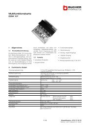
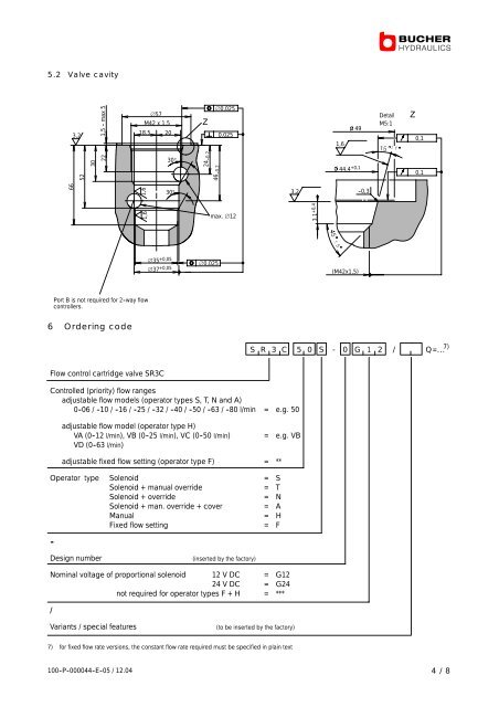
5.2 Valve cavity<br />
66<br />
3,2<br />
52<br />
1,5 - max 5<br />
30<br />
22<br />
1,6<br />
1,6<br />
Port B is not required for 2 -way flow<br />
controllers.<br />
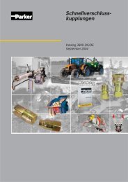
6 Ordering code<br />
∅57<br />
M42 x 1,5<br />
18,5 20<br />
∅37 +0,05<br />
∅35 +0,05<br />
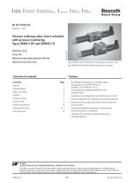
<strong>Flow</strong> control cartridge valve SR3C<br />
30°<br />
30°<br />
24 - 0,2<br />
46 - 0,2<br />
∅0,025<br />
∅0,025<br />
0,025<br />
max. ∅12<br />
<strong>Control</strong>led (priority) flow ranges<br />
adjustable flow models (operator types S, T, N <strong>and</strong> A)<br />
0-06 / -10 / -16 / -25 / -32 / -40 / -50 / -63 / -80 l/min = e.g. 50<br />
adjustable flow model (operator type H)<br />
VA (0 -12 l/min), VB (0 -25 l/min), VC (0 -50 l/min) = e.g. VB<br />
VD (0 -63 l/min)<br />
adjustable fixed flow setting (operator type F) = **<br />
Operator type Solenoid = S<br />
Solenoid + manual override = T<br />
Solenoid + override = N<br />
Solenoid + man. override + cover = A<br />
Manual = H<br />
Fixed flow setting = F<br />
-<br />
Design number (inserted by the factory)<br />
Nominal voltage of proportional solenoid 12 V DC = G12<br />
24 V DC = G24<br />
not required for operator types F + H = ***<br />
/<br />
Variants / special features (to be inserted by the factory)<br />
7) for fixed flow rate versions, the constant flow rate required must be specified in plain text<br />
Z<br />
Detail Z<br />
M5:1<br />
100 -P -000044 -E -05 / 12.04 4/8<br />
3,2<br />
3.1 +0,4<br />
1,6<br />
49<br />
44.4 +0,1<br />
(M42x1,5)<br />
- 0,3<br />
S R 3 C 5 0 S - 0 G 1 2 / Q=... 7)<br />
0,1<br />
0,1