Specifications - Gilberts (Blackpool)
Specifications - Gilberts (Blackpool)
Specifications - Gilberts (Blackpool)

Create successful ePaper yourself
Turn your PDF publications into a flip-book with our unique Google optimized e-Paper software.
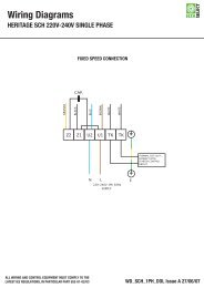
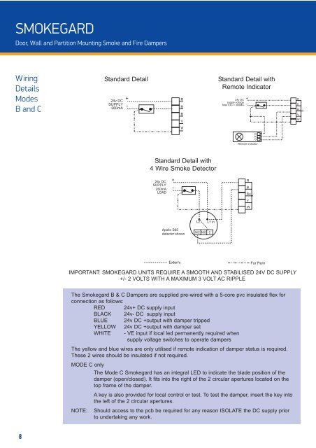
SMOKEGARD<br />
Door, Wall and Partition Mounting Smoke and Fire Dampers<br />
Wiring<br />
Details<br />
Modes<br />
B and C<br />
Standard Detail<br />
24v DC<br />
SUPPLY<br />
260mA<br />
+<br />
-<br />
R<br />
B<br />
B<br />
Standard Detail with<br />
Remote Indicator<br />
24v DC<br />
supply voltage<br />
Max IDC = 300MA<br />
+<br />
-<br />
R<br />
B<br />
Bu<br />
Y<br />
Y<br />
W<br />
W<br />
O<br />
R<br />
G<br />
Remote Indicator<br />
Standard Detail with<br />
4 Wire Smoke Detector<br />
24v DC<br />
SUPPLY<br />
260mA<br />
LOAD<br />
+<br />
-<br />
R<br />
B<br />
Bu<br />
Y<br />
W<br />
L2<br />
L1 in<br />
Apollo S65<br />
detector shown<br />
N/C N/O C<br />
Externa<br />
For Perm<br />
IMPORTANT: SMOKEGARD UNITS REQUIRE A SMOOTH AND STABILISED 24V DC SUPPLY<br />
+/- 2 VOLTS WITH A MAXIMUM 3 VOLT AC RIPPLE<br />
The Smokegard B & C Dampers are supplied pre-wired with a 5-core pvc insulated flex for<br />
connection as follows:<br />
RED 24v+ DC supply input<br />
BLACK 24v- DC supply input<br />
BLUE 24v DC +output with damper tripped<br />
YELLOW 24v DC +output with damper set<br />
WHITE - VE input if local led permanently required when<br />
supply voltage switches to operate dampers<br />
The yellow and blue wires are only utilised if remote indication of damper status is required.<br />
These 2 wires should be insulated if not required.<br />
MODE C only<br />
The Mode C Smokegard has an integral LED to indicate the blade position of the<br />
damper (open/closed). It fits into the right of the 2 circular apertures located on the<br />
top frame of the damper.<br />
A key is also provided for local control or test. To test the damper, insert the key into<br />
the left of the 2 circular apertures.<br />
NOTE: Should access to the pcb be required for any reason ISOLATE the DC supply prior<br />
to undertaking any work.<br />
8