Specifications - Gilberts (Blackpool)
Specifications - Gilberts (Blackpool)
Specifications - Gilberts (Blackpool)

Create successful ePaper yourself
Turn your PDF publications into a flip-book with our unique Google optimized e-Paper software.
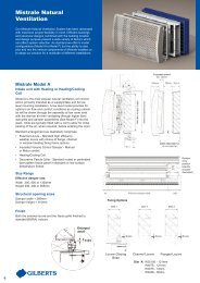
Installation<br />
Procedures<br />
Door Mounted or Light Structure Partitions<br />
1. Aperture to be cut into door to match the<br />
DAMPER size (Aperture dimensions<br />
detailed on page 5).<br />
2. The backing sleeve should now be<br />
entered into the opening to allow marking<br />
of fixing bolt hole locations.<br />
3. Remove the backing sleeve and drill 5mm<br />
diameter bolt holes where marked.<br />
MARK BOLT HOLES<br />
THROUGH<br />
DAMPER FRAME<br />
4. MODE A Type unit can be reinstalled in<br />
the aperture and, with the mating back<br />
DOOR<br />
sleeve inserted on<br />
the opposite side,<br />
secured using<br />
EXCESS THREAD<br />
CUTOFF AFTER<br />
INSTALLATION<br />
the set of<br />
TO SUIT<br />
DOOR WIDTH<br />
screws and * DAMPER<br />
16SWG<br />
nuts provided. GALVANISED STEEL<br />
BACKINGSLEEVE<br />
FITS OUTSIDE<br />
REAR OF DAMPER<br />
INTUMESCENT<br />
SEAL AT BACK<br />
OF FLANGE<br />
FIXING SCREWS<br />
AND NUTS<br />
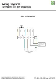
MODE B & C Type units will<br />
now require electrical<br />
connection before completing<br />
installation. After the aperture<br />
has been cut into the door a<br />
6mm diameter wiring hole must<br />
be drilled from the door edge,<br />
through the centre of the door,<br />
in line with the top of the<br />
damper from the door to to the<br />
jamb. Upon reaching the edge<br />
of the door therefore, a routing<br />
will then need to be made to<br />
allow the cable to enter the<br />
loop, as illustrated, for terminal<br />
block connection. (The damper<br />
cable is colour coded. Please<br />
refer to Wiring Diagram for<br />
correct connection). The<br />
damper can then be installed<br />
and, with the mating back<br />
sleeve inserted on the opposite<br />
side, secured using the set<br />
screws and nuts provided.<br />
ROUTING<br />
ELECTRICAL<br />
LOOP<br />
6mm dia<br />
WIRING HOLE<br />
DAMPER<br />
APERTURE<br />
5. The Fascia Grilles can now<br />
be fitted over the damper<br />
and fixed with self tapping<br />
screws provided.<br />
16SWG<br />
GALVANISED<br />
STEEL SLEEVE<br />
FITS OUTSIDE<br />
REAR OF DAMPER<br />
DOOR<br />
* DAMPER<br />
INTUMESCENT<br />
SEAL AT BACK<br />
OF FLANGE<br />
FIXING SCREWS<br />
AND NUTS<br />
FASCIA GRILLE<br />
TYPE A OR B<br />
(TYPE A ILLUSTRATED)<br />
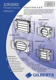
Wall Mounting<br />
1. Aperture to be cut into wall to match<br />
the damper size (aperture dimensions<br />
detailed on page 5).<br />
50mm<br />
CABLE ENTRY POINT<br />
10mm<br />
50mm<br />
2. The rear sleeve should now be fixed<br />
into the wall and secured with suitable<br />
screws (and plugs if necessary)<br />
through the flange.<br />
3. Mode A type Dampers, which do not<br />
require an electrical connection, can<br />
now be fitted from the front and<br />
secured with suitable screws (and<br />
plugs if necessary) through the flange.<br />
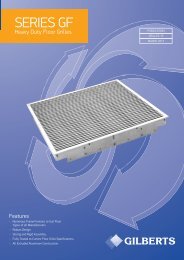
4. Mode B and C type Dampers, require<br />
electrical connection before installation<br />
is complete.<br />
The dampers are supplied<br />
with approximately one<br />
metre of flex to which a<br />
secure insulated connection<br />
is recommended.<br />
16 SWG GALVANISED<br />
STEEL SLEEVE<br />
WALL<br />
*<br />
DAMPER<br />
The damper cable is colour<br />
coded. Please refer to Wiring<br />
Diagram for<br />
correct<br />
connection<br />
Once these<br />
connections<br />
have been<br />
completed the<br />
damper can be<br />
fitted into the<br />
aperture and<br />
*<br />
16 SWG GALVANISED<br />
STEEL SLEEVE<br />
secured with suitable screws<br />
(and plugs if necessary)<br />
through the flange.<br />
5. The front and rear fascia<br />
grilles for all modes can<br />
then be fitted over the<br />
damper and fixed with the<br />
self tapping screws<br />
provided through the holes<br />
in the flanges.<br />
*<br />
It is recommended that an<br />
Intumescent Sealant is<br />
inserted at this point<br />
between the overlapping<br />
sleeves.<br />
WALL<br />
DAMPER<br />
FACIA GRILLE<br />
TYPE A OR B<br />
(B ILLUSTRATED)<br />
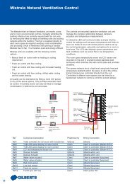
Maintenance of Components<br />
All units are tested before leaving the factory, but should be test operated prior to commissioning and<br />
regularly thereafter to ensure correct operation. Test frequency will depend upon Damper environment<br />
however a maximum interval of 6 months is recommended. In addition an Annual Visual Inspection is also<br />
advisable to permit cleaning and removal of any airborne contaminants which may affect the Damper<br />
operation. (NB for safety the Damper Blades should be closed before personally approaching them for<br />
inspection/cleaning).<br />
The Dampers contain no other user serviceable parts, any faults are best referred to the manufacturer.<br />
9