T-Series Instruction Manual 120V - Brightline
T-Series Instruction Manual 120V - Brightline
T-Series Instruction Manual 120V - Brightline

You also want an ePaper? Increase the reach of your titles
YUMPU automatically turns print PDFs into web optimized ePapers that Google loves.
T-<strong>Series</strong><br />
Installation and Operating<br />
<strong>Instruction</strong>s<br />
580 Mayer Street, Building #7, Bridgeville, PA 15017 • phone 412.206.0106 • fax 412.206.0146 www.brightlines.com<br />
© 2011 <strong>Brightline</strong>, L.P.<br />
1
Safety<br />
• Fixture installation should be performed in accordance with local and national codes.<br />
All fixtures must be properly grounded.<br />
• To prevent fire or electric shock, do not expose the fixtures to water or moisture. T-<strong>Series</strong><br />
fixtures are Listed for indoor use only.<br />
• Do not attempt to dim a non-dim fixture. Do not attempt to operate without lamps installed, as this<br />
could damage the ballast.<br />
• Do not attempt to change the lamps on a fixture that is energized, or to work with your hands near<br />
an exposed socket that is energized.<br />
• A qualified technician should perform service on fixtures. Do not remove the ballast cover until the<br />
unit has been de-energized.<br />
• In case of lamp failure:<br />
1. Turn the fixture off.<br />
2. Wait 30 seconds for the ballast to reset.<br />
3. Install the new lamp(s).<br />
Owner’s Record<br />
• The serial number of this product can be found in the top of the fixture. You should note<br />
the model number and the serial number in the space provided and retain this book for future<br />
reference as a permanent record of your purchase.<br />
Model No.________________________<br />
Serial No.________________________<br />
Date of Purchase__________________<br />
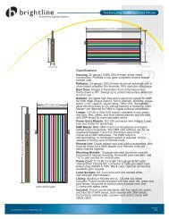
Product Description<br />
• The <strong>Brightline</strong> T-<strong>Series</strong> models are single or multi-cell 55-watt, energy-efficient, videoconferencing<br />
fixtures that mounts as a replacement for ceiling tiles in a T-bar suspended ceiling grid. These fixtures<br />
combine high-frequency electronics with a state-of-the-art optical system to produce a soft, full-spectrum,<br />
flicker free light source.<br />
Mini Mount<br />
Offset Mount<br />
Double Dome<br />
2<br />
Center Mount<br />
45° Mount
Specifications<br />
Housing:<br />
20-gauge (.0359) formed, cold rolled steel sheet-metal construction. See finish note.<br />
Reflector:<br />
24-gauge (.020) formed aluminum sheet-metal construction. Polished spectral finish.<br />
95% specular reflectance.<br />
Ballast:<br />
Power factor = >.97 Class “A” sound rating and THD:
Installation<br />
1. Unpack the fixtures. The control screens and lamps may be packed with the fixtures or separately. To<br />
prevent damage, do not attempt to install the fixtures with either the lamps or the control screens in place.<br />
2. Prepare the line voltage wiring to the fixtures. You may want to partially install the power wiring before the<br />
fixture is placed in the t-track, if access is difficult. Insure that the supply voltage matches that required by<br />
the ballasts. To install the power feed, loosen the screw holding the power entry plate and remove the<br />
plate (Figure 1). Remove the knockouts as needed and install the correct type of power cabling and strain<br />
relief (not provided). Connect the wires from the feed using wire-nuts, observing the wire color coding, and<br />
re-install the knockout plate. <strong>Brightline</strong> fixtures intended for the North American market use<br />
black/white/green wires respectively for line/neutral/ground; fixtures shipped to other locations use<br />
brown/blue/green-yellow for line/neutral/ground. In most cases, it is useful to install sufficient slack in the<br />
power cable so that the fixture may be moved to an adjacent tile opening without having to extend the wiring.<br />
Figure 1<br />
3. If the fixture requires digital control, the fixture will have locking XLR-type plugs for the control cables.<br />
Install the control wiring above the t-track grid. Male and female plugs are installed into receptacles<br />
(Figure 2) on each fixture; as they are wired in parallel, the control wiring can be daisy-chained.<br />
See the Control Wiring section.<br />
Figure 2<br />
4. Prepare the t-track to receive the fixtures. TD-<strong>Series</strong> fixtures are either a nominal 1’ x 2’ (300mm x 600mm)<br />
or a 2’ x 2’ (600mm x 600mm) size. It may be necessary to add additional track sections and/or prepare<br />
differently sized ceiling tiles. For ease of installation, a minimum of 8” (200mm) of clear height above the<br />
track recommended. Make sure that the t-track is sufficiently braced to accept the weight of the fixtures;<br />
these units are heavier than typical fixtures.<br />
5. Place the fixtures into the correct openings in the ceiling grid in accordance with plans provided by<br />
<strong>Brightline</strong> or the local architect or engineer. <strong>Brightline</strong> fixtures are not Insulated Ceiling (IC) rated.<br />
Maintain the proper distance from insulation.<br />
4
Installation<br />
6. Install “safety wires” on the tabs on the side of the fixtures and attach to the building structure, in compliance<br />
with local codes (Figure 3). <strong>Brightline</strong> recommends not relying on the t-track alone to hold the weight of the<br />
Safety Tabs<br />
4-Places<br />
Figure 3<br />
7. Complete the installation of the power (and control, if required) wiring. See the Riser Diagram section.<br />
8. With the power off, install the lamps (Figure 4). Make sure they are firmly seated in their sockets.<br />
Note: The socket’s locking tabs will snap into the indentations on the base of the lamp.<br />
Clip<br />
Lamp<br />
Figure 4<br />
9. Install the correct control screens (Figure 5).<br />
a.) Insert the end of the control screen into the socket end of the carriage.<br />
b.) Push the opposite end of the control screen up into the carriage.<br />
c.) Release the control screen and the retaining spring will secure the control screen in the carriage.<br />
Figure 5<br />
5
Installation<br />
10. Aim the fixture carriages in compliance with directions provided by <strong>Brightline</strong> or the specifier.<br />
<strong>Brightline</strong> TD-<strong>Series</strong> fixtures are available in three types of articulations:<br />
<strong>Manual</strong> rotation on a single-axis.<br />
a.) Rotate the carriage to the desired position (Figure 6).<br />
b.) Slide the carriage to the side for greater range of angular movement (Figure 7).<br />
Figure 6 Figure 7<br />
Drop-Pan-Tilt on three-axis.<br />
a.) Rotate the carriage to access the retaining clip (Figure 8).<br />
b.) While grasping the carriage, pivot the retaining clip to release the carriage from the home<br />
position (Figure 8).<br />
c.) With the carriage in hand, allow the carriage to drop down from the main housing (Figure 9).<br />
d.) Pan the carriage to the desired location (Figure 10).<br />
e.) Loosen pivot screws, adjust tilt to desired position, and retighten screws when done (Figure 10).<br />
Retaining<br />
Clip<br />
LOOSEN SCREWS TO FOCUS<br />
TIGHTEN WHEN DONE<br />
(#2 PHILIPS DRIVER)<br />
180° MAX<br />
Figure 8 Figure 9<br />
Figure 10<br />
Motorized rotation on a single-axis.<br />
See the motorized control system documentation for further information.<br />
Warning: <strong>Manual</strong>ly rotating lamp carriage can cause damage to both the motor and the drive systems.<br />
Do not use lamp carriage as an installation handle.<br />
6
Non-Dim (Switched) Riser Diagram<br />
Non-Dim (Switched)<br />
• The fixture may be controlled by a local on/off switch, or by a relay panel.<br />
• The fixture is wired to a source of power (Hot/Neutral/Ground) wiring only.<br />
• H = Constant Hot, N = Neutral, G = Ground.<br />
7
Phase-Control (Two-wire) Riser Diagram<br />
Phase-Control Dimmed (two-wire)<br />
• Connect your fixtures to the output of Forward Phase-Fired dimmers. Most dimmers are of this type:<br />
“SCR” and “SSR” dimmers work in this way, as do most architectural dimmers. The use of Reverse<br />
Phase-Fired dimmers is not recommended. If it is possible to set the type of load the dimmer will control,<br />
configure it as a two-wire fluorescent type; or choose one intended for a two-wire fluorescent ballast.<br />
• H = Constant Hot, N = Neutral, G = Ground.<br />
8
Phase-Control Dimmed Lutron (Three-wire) Riser Diagram<br />
Phase-Control Dimmed Lutron (three-wire)<br />
• These units will typically have Lutron Hi-Lume, ECO-10, or EcoSystem ballasts. They are designed<br />
to be controlled by fluorescent controllers that provide a dimmed “hot” wire and a switched “hot” wire,<br />
in addition to neutral and ground.<br />
• At the ballast, the switched feed wire is black in color and the dimmed feed wire is orange. <strong>Brightline</strong><br />
recommends maintaining a consistent wire color-coding scheme from the controller to the fixture.<br />
• Choose controllers that are intended for this type of ballast.<br />
• DH = Dimmed Hot, SH = Switched Hot, H = Constant Hot, N = Neutral, G = Ground.<br />
9
Digital Dimmed (DMX Controlled) Riser Diagram<br />
Note:<br />
Power wiring for one<br />
fixture shown for<br />
DMX Dimmed<br />
• A DSI (Digital Serial Interface) signal controls these fixtures. The fixtures will function (but not dim) in<br />
the absence of a control signal.<br />
• A DMX to DSI converter may have been provided by <strong>Brightline</strong> as part of your Order. The Converter is<br />
wired to a source of DMX; and provides four DSI outputs with XLR receptacles. The fixtures cannot be<br />
directly controlled by DMX. See the instruction manual provided with the DMX to DSI converter.<br />
• The control signal is connected to the fixture through the XLR-type plug on the top of the unit. As this is<br />
low voltage wiring, it may not be necessary to install the control wiring in conduit, subject to the<br />
requirements of local code. If they were specified, the DSI control cables may be provided as part<br />
of your Order. Two receptacles are typically provided to allow the control wiring to be daisy-chained.<br />
• All the fixtures wired on a DSI control line will dim to the same intensity.<br />
• H = Constant Hot, N = Neutral, G = Ground.<br />
10
Digital Dimmed (DALI with Wall Controller) Riser Diagram<br />
DALI<br />
BUSMaster<br />
<strong>120V</strong> AC to<br />
12V DC<br />
(Included with<br />
Busmaster)<br />
DALI Push Button<br />
Control Panel<br />
Note:<br />
Power wiring for one<br />
fixture shown for<br />
DALI Dimmed<br />
• A DALI (Digital Addressable Low-voltage Interface) signal controls these fixtures. The fixtures will function<br />
(but not dim) in the absence of a control signal.<br />
• The control signal is connected to the fixture through the XLR-type plug on the top of the unit. As this is<br />
low voltage wiring, it may not be necessary to install the control wiring in conduit, subject to the<br />
requirements of local code. If they were specified, the DALI control cables may be provided as part<br />
of your Order. Two receptacles are typically provided to allow the control wiring to be daisy-chained.<br />
• As each ballast is assigned an individual address, fixtures on a DALI control line may be dimmed to<br />
different intensities.<br />
• The installation of DALI control wiring must comply with a specific set of rules. See the literature that is<br />
provided with your DALI controller, or contact <strong>Brightline</strong> for details.<br />
• H = Constant Hot, N = Neutral, G = Ground.<br />
11
Digital Dimmed (DALI with RS-232 Busmaster) Riser Diagram<br />
DALI Push Button<br />
Control Panel<br />
(OPTIONAL)<br />
DALI<br />
BUSMaster<br />
<strong>120V</strong> AC to<br />
12V DC<br />
(Included with<br />
Busmaster)<br />
Note:<br />
Power wiring for one<br />
fixture shown for<br />
DALI Dimmed<br />
• A DALI (Digital Addressable Low-voltage Interface) signal controls these fixtures. The fixtures will function<br />
(but not dim) in the absence of a control signal.<br />
• The control signal is connected to the fixture through the XLR-type plug on the top of the unit. As this is<br />
low voltage wiring, it may not be necessary to install the control wiring in conduit, subject to the<br />
requirements of local code. If they were specified, the DALI control cables may be provided as part<br />
of your Order. Two receptacles are typically provided to allow the control wiring to be daisy-chained.<br />
• As each ballast is assigned an individual address, fixtures on a DALI control line may be dimmed to<br />
different intensities.<br />
• The installation of DALI control wiring must comply with a specific set of rules. See the literature that is<br />
provided with your DALI controller, or contact <strong>Brightline</strong> for details.<br />
• H = Constant Hot, N = Neutral, G = Ground.<br />
12<br />
Doc: 019-228.P65<br />
Rev: E
Trouble Shooting Guide<br />
Problem<br />
Lights go to full but do not<br />
dim to minimum.<br />
Possible Cause<br />
1. Ballasts are not proper grounded.<br />
2. Lamps are too old.<br />
Solution<br />
1. Check to see that the fixture is properly<br />
grounded.<br />
2. Relamp the entire fixture.<br />
Lights flicker or drop out<br />
at low end.<br />
Defective or damaged lamps.<br />
Test with lamps from a known good fixture;<br />
replace bad lamps as required.<br />
Lights are flashing or<br />
strobing.<br />
Wrong Voltage for the ballast installed.<br />
Verify that the supply voltage is correct for the<br />
ballast installed.<br />
Lamps are not at the<br />
same light level.<br />
Mixture of lamp ages or color<br />
temeratures.<br />
Check that all the lamps are of the same type<br />
and age.<br />
Ballast buzzes or hums.<br />
Defective ballast.<br />
Identify the location of the buzz and replace the<br />
ballast if necessary.<br />
Maintenance<br />
• The fluorescent lamps provided with the fixtures are rated for up to 10,000 hours. However, as with all<br />
lamps, there will be some drop-off in intensity as they approach their rated life. A conservative user may<br />
want to re-lamp at 75-80% of the rated life. We recommend that as the lamp intensity begins drop off,<br />
or when the life expectancy is reached, all the lamps in a room are replaced as a group.<br />
• The lamps provided with your brightline fixture have been selected to provide the correct operating<br />
parameters for your video system. All lamps should be replaced with ones having an identical model<br />
number and manufacturer. It may be necessary to perform a new white-balance on your camera(s) after<br />
re-lamping. Call your <strong>Brightline</strong> dealer or representative if you need assistance in purchasing replacement<br />
lamps.<br />
• For optimal performance, Season lamps for 12 hours prior to dimming.<br />
Note: Approximate initial Lumens after 100 hours of operation.<br />
• Dispose of used fluorescent lamps in conformance with local regulations.<br />
• For optimal fixture performance, it is necessary to keep the lamps and reflectors clean. Use a dry,<br />
non-abrasive cloth to remove dust. Avoid the use of materials that might scratch the reflector.<br />
13
Exploded Assembly<br />
7 10<br />
4 11<br />
5<br />
6 3<br />
39<br />
29<br />
26<br />
19<br />
22<br />
21<br />
35<br />
9<br />
25<br />
42 43<br />
8 10<br />
23<br />
24<br />
15<br />
28<br />
30<br />
24<br />
31<br />
19<br />
34 33<br />
6<br />
12<br />
36<br />
38<br />
ITEM<br />
NO.<br />
PART NUMBER<br />
DESCRIPTION<br />
1 PEM S-632-0 ZI--N PEM NUT, #6-32<br />
2 90087A151<br />
SCREW, 6-32x3/4" PH, PAD SELF<br />
TAP<br />
3 021-401<br />
UNIVERSAL FEMALE SLIDE<br />
BRACKET<br />
4 014-283 3 PIN XLR CONNECTOR, MALE<br />
5 021-398<br />
UNIVERSAL MALE SLIDE<br />
BRACKET<br />
6 010-145-007<br />
6-32x.3/8 Phil Pan Hd Screw<br />
w/int Tooth Lock Washer<br />
7 010-147-005 4-40 x .31 Flat Hd Screw<br />
8 021-277 Rev B POWER MOUNTING BRACKET<br />
9 021-367 Rev D UNIVERAL XLR PLATE<br />
10 010-165-005<br />
6-32x.50 Hex Washer Hd Screw,<br />
Self Tap<br />
11 014-286<br />
3 PIN XLR CONNECTOR,<br />
FEMALE<br />
12 021-364 Rev B UNIV HOUSING DOME INSERT<br />
13<br />
021-403 Detail D<br />
Rev B<br />
UNIV HOUSING 2-LAMP<br />
CARRIAGE SCREEN SPRING<br />
14<br />
021-403 Detail B<br />
Rev B<br />
UNIV HOUSING CARRIAGE 2-<br />
LAMP LEFT END CAP<br />
15 021-403 Detail A<br />
UNIV HOUSING CARRIAGE 2-<br />
LAMP<br />
16<br />
PEM BSO-632-20 ZI--<br />
N<br />
STAND OFF 6-32 X .625 ZINC<br />
17<br />
021-403 Detail C<br />
Rev B<br />
UNIV HOUSING CARRRIAGE 2-<br />
LAMP RIGHT END CAP<br />
18 PEM FH-632-5 ZC-n STUD, 6-32 X .31 FH, ZINC<br />
19 012-133 #6 X1/16" NYLON WASHER<br />
20 010-105-005<br />
SCREW, #6-32X3/8, PHIL PAN<br />
HD<br />
21 022-185<br />
UNIV HOUSING 2-LAMP<br />
SCREEN FRAME<br />
22 016-209 T02 FIXTURE WHITE LENS<br />
23 008-151<br />
BALLAST, TRIDONIC 2X54<br />
One4all<br />
24 90675A007 NUT, 6-32, KEPS, ZINC<br />
25 011-114-005 #4-40 KEPS NUT<br />
26 004-118<br />
UNVI HOUSING 2-LAMP<br />
CARRIAGE SOCKET BRACKET<br />
27 PEM S-440-0 ZI--N PEM NUT, #4-40 ZINC<br />
28 006-106 2G11 LAMP HOLDER W/FEET<br />
29 90403A108<br />
SCREW, 4-40 X 3/8 PHL PAN W/<br />
INT WASHER<br />
30 003-138 Rev B<br />
UNIV HOUSING 2-LAMP<br />
CARRIAGE REFLECTOR<br />
31 020-101 LAMP SUPPORT T5 BIAX<br />
32 012-115<br />
#6 THIN FLAT WASHER<br />
.149"IDX.375"ODX.032"TK<br />
33 015-122<br />
Pop Rivet .125" dia. .126"-.187"<br />
Grip<br />
34 010-123-005<br />
SCREW, 6-32X5/16 LG PHIL PAN<br />
HD W/INT TOOTH LOCK<br />
WASHER<br />
35 021-374 Rev B PANEL, INCH, CENTER, SOLID<br />
36 021-392<br />
UNIVERSAL PANEL MTG<br />
BRACKET<br />
37 021-392<br />
UNIVERSAL PANEL MTG<br />
BRACKET<br />
38 010-168-005<br />
8-32 X .375 Hex Washer type F<br />
Zinc<br />
39 021-365<br />
UNIV MAIN HOUSING COVER<br />
REV. C<br />
40 022-121 Medium Field Screen<br />
33<br />
41 009-55W-32KSP LAMP, 55W TWIN TUBE 32K<br />
42 001-144 Detail A UNIVERSAL HOUSING REV. C<br />
43 001-144 Detail B<br />
UNIV HOUSING END CAP REV.<br />
C<br />
T02X1-R-ISCM SHOWN<br />
14<br />
Doc: 019-228.P65<br />
Rev: D
WARRANTY<br />
<strong>Brightline</strong> guarantees all its products to be free from defects in materials and<br />
workmanship for a period of one (1) year from the date of shipment.<br />
PROCEDURES<br />
If any product is found to be unsatisfactory under this warranty, the buyer must notify<br />
<strong>Brightline</strong> immediately. Once a course of action has been determined, if it is necessary<br />
to return the product to <strong>Brightline</strong> a Return Authorization (RA) will be issued.<br />
Ship the product directly to <strong>Brightline</strong>, 580 Mayer Street, Building #7, Bridgeville, PA<br />
15017. The RA number should be marked on the shipping carton. The unit will be<br />
replaced or put into proper operating condition, free of all charges. The correction of<br />
any defects through repair or replacement by <strong>Brightline</strong> shall constitute fulfillment of<br />
all obligations and liability of <strong>Brightline</strong> to the buyer under this warranty and the<br />
contract of sale.<br />
DISCLAIMERS<br />
<strong>Brightline</strong> is not responsible for damage to its products caused by improper<br />
installation, maintenance, or use; by improper electrical hookups; or by unauthorized<br />
repairs.<br />
Failure to notify <strong>Brightline</strong> of unsatisfactory operation or any improper or<br />
unauthorized installation, maintenance, use, repairs, or adjustments shall terminate the<br />
warranty and <strong>Brightline</strong> shall have no further responsibility under the warranty.<br />
<strong>Brightline</strong> shall not be liable for special or consequential damages in any claim,<br />
action, suit, or proceeding arising under this warranty or contract of sale, nor shall<br />
<strong>Brightline</strong> be liable for claims for labor, loss of profits or goodwill, repairs, or other<br />
expenses incidental to replacement. <strong>Brightline</strong> makes no other warranty of any kind<br />
whatsoever, expressed or implied, and all implied warranties of merchantability and<br />
fitness for a particular purpose that exceed the obligation specifically described in this<br />
warranty are hereby disclaimed by <strong>Brightline</strong> and excluded from this agreement.<br />
All shipments, unless otherwise noted, are F.O.B. factory.<br />
The customer is advised to inspect for shipping damage, apparent and/or hidden.<br />
If detected, notify the transportation company and file your claim.<br />
580 Mayer Street, Building #7, Bridgeville, PA 15017 • phone 412.206.0106 • fax 412.206.0146<br />
www.brightlines.com<br />
15
Notes<br />
16