Inflatable Solar Arrays: Revolutionary Technology? - Team-Logic
Inflatable Solar Arrays: Revolutionary Technology? - Team-Logic
Inflatable Solar Arrays: Revolutionary Technology? - Team-Logic

Create successful ePaper yourself
Turn your PDF publications into a flip-book with our unique Google optimized e-Paper software.
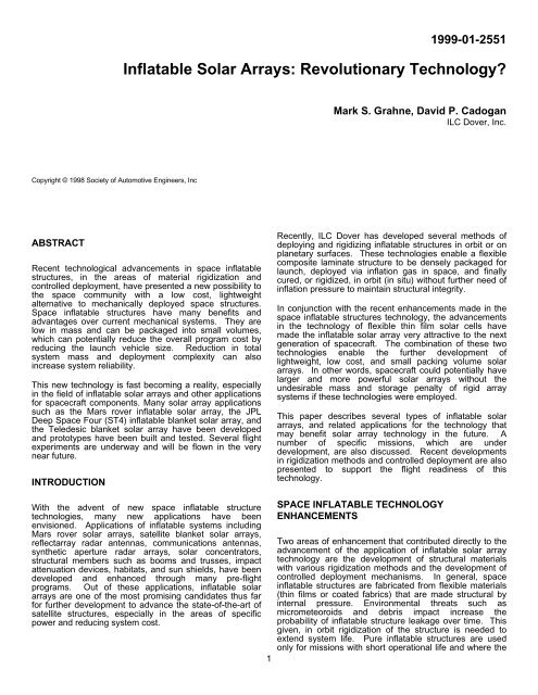
1999-01-2551<br />
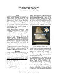
<strong>Inflatable</strong> <strong>Solar</strong> <strong>Arrays</strong>: <strong>Revolutionary</strong> <strong>Technology</strong><br />
Mark S. Grahne, David P. Cadogan<br />
ILC Dover, Inc.<br />
Copyright © 1998 Society of Automotive Engineers, Inc<br />
ABSTRACT<br />
Recent technological advancements in space inflatable<br />
structures, in the areas of material rigidization and<br />
controlled deployment, have presented a new possibility to<br />
the space community with a low cost, lightweight<br />
alternative to mechanically deployed space structures.<br />
Space inflatable structures have many benefits and<br />
advantages over current mechanical systems. They are<br />
low in mass and can be packaged into small volumes,<br />
which can potentially reduce the overall program cost by<br />
reducing the launch vehicle size. Reduction in total<br />
system mass and deployment complexity can also<br />
increase system reliability.<br />
This new technology is fast becoming a reality, especially<br />
in the field of inflatable solar arrays and other applications<br />
for spacecraft components. Many solar array applications<br />
such as the Mars rover inflatable solar array, the JPL<br />
Deep Space Four (ST4) inflatable blanket solar array, and<br />
the Teledesic blanket solar array have been developed<br />
and prototypes have been built and tested. Several flight<br />
experiments are underway and will be flown in the very<br />
near future.<br />
INTRODUCTION<br />
Recently, ILC Dover has developed several methods of<br />
deploying and rigidizing inflatable structures in orbit or on<br />
planetary surfaces. These technologies enable a flexible<br />
composite laminate structure to be densely packaged for<br />
launch, deployed via inflation gas in space, and finally<br />
cured, or rigidized, in orbit (in situ) without further need of<br />
inflation pressure to maintain structural integrity.<br />
In conjunction with the recent enhancements made in the<br />
space inflatable structures technology, the advancements<br />
in the technology of flexible thin film solar cells have<br />
made the inflatable solar array very attractive to the next<br />
generation of spacecraft. The combination of these two<br />
technologies enable the further development of<br />
lightweight, low cost, and small packing volume solar<br />
arrays. In other words, spacecraft could potentially have<br />
larger and more powerful solar arrays without the<br />
undesirable mass and storage penalty of rigid array<br />
systems if these technologies were employed.<br />
This paper describes several types of inflatable solar<br />
arrays, and related applications for the technology that<br />
may benefit solar array technology in the future. A<br />
number of specific missions, which are under<br />
development, are also discussed. Recent developments<br />
in rigidization methods and controlled deployment are also<br />
presented to support the flight readiness of this<br />
technology.<br />
With the advent of new space inflatable structure<br />
technologies, many new applications have been<br />
envisioned. Applications of inflatable systems including<br />
Mars rover solar arrays, satellite blanket solar arrays,<br />
reflectarray radar antennas, communications antennas,<br />
synthetic aperture radar arrays, solar concentrators,<br />
structural members such as booms and trusses, impact<br />
attenuation devices, habitats, and sun shields, have been<br />
developed and enhanced through many pre-flight<br />
programs. Out of these applications, inflatable solar<br />
arrays are one of the most promising candidates thus far<br />
for further development to advance the state-of-the-art of<br />
satellite structures, especially in the areas of specific<br />
power and reducing system cost.<br />
1<br />
SPACE INFLATABLE TECHNOLOGY<br />
ENHANCEMENTS<br />
Two areas of enhancement that contributed directly to the<br />
advancement of the application of inflatable solar array<br />
technology are the development of structural materials<br />
with various rigidization methods and the development of<br />
controlled deployment mechanisms. In general, space<br />
inflatable structures are fabricated from flexible materials<br />
(thin films or coated fabrics) that are made structural by<br />
internal pressure. Environmental threats such as<br />
micrometeoroids and debris impact increase the<br />
probability of inflatable structure leakage over time. This<br />
given, in orbit rigidization of the structure is needed to<br />
extend system life. Pure inflatable structures are used<br />
only for missions with short operational life and where the
supply of make up gas does not pose a problem. Most of<br />
the applications discussed below require in situ rigidization<br />
to provide long term structural integrity.<br />
RIGIDIZABLE STRUCTURES<br />
Space rigidized structures are fabricated from flexible<br />
composite laminates that are rigidized in situ via some<br />
external influence. They can be fabricated into many<br />
different shapes such as toroids, spheres, dish structures,<br />
tubes, etc., which can be designed into various types of<br />
structures. This class of structures can be deployed in<br />
various orbits and in gravitational surface environments<br />
such as the Moon or Mars. The rigidized components are<br />
designed for typical operational lifetimes of seven to<br />
fifteen years without environmental concerns.<br />
Over the last forty years many rigidization methods have<br />
been investigated sporadically. However, with more<br />
intensive research and development in the recent years by<br />
the space inflatable industry, many reliable rigidized<br />
structural components have been produced through the<br />
use of advanced materials and design. Some of the most<br />
promising rigidization methods include:<br />
• Heat Cured Thermoset Composite Laminates<br />
(Thermal Heating)<br />
• Thin-walled Aluminum/polyimide Laminates<br />
• Thermoplastic Composite Laminates (Passive<br />
Cooling)<br />
• UV Curable Composite Laminates<br />
• Foam Inflation<br />
• Inflation Gas Reaction Laminates<br />
Out of these rigidization methods ‘Thermal Heating’ and<br />
‘Thin-walled Aluminum’ are the most promising for space<br />
and planetary surface applications respectively. The<br />
Thermal Heating method is currently under further<br />
development at ILC Dover for flight experiment in the year<br />
2000. The Thin-walled Aluminum System and the<br />
Thermal Heating System will be discussed in greater<br />
detail later. For further information on other methods of<br />
rigidization the reader is encouraged to consult the<br />
reference documents listed in the paper.<br />
Figure 1 - Composite Laminate Cross-Section<br />
The MLI heating blanket is designed and fabricated from<br />
various layers of vapor-deposited aluminum (VDA)<br />
Kapton, VDA Mylar, and spacers. The purpose of the MLI<br />
blanket is to keep out the harsh space environment and at<br />
the same time maintain the required curing temperature<br />
inside. The design of the MLI blanket is tailored to the<br />
specific mission environment and requirements. The<br />
support tube laminate typically consists of four separate<br />
layers: (1) The restraint layer that maintains the shape of<br />
the inflatable structure; (2) The heater assembly layer<br />
which provides the proper temperature for deployment<br />
and curing (in some designs the restraint layer and the<br />
heater layer are combined to become one assembly); (3)<br />
The rigidizable composite laminate layer, fabricated<br />
from prepreg materials such as epoxy/graphite, is the<br />
support structure when cured; And (4) The bladder layer,<br />
manufactured from black Kapton, keeps and maintains<br />
inflation pressure during deployment. The thermoplastic<br />
composite laminates, which use passive cooling as the<br />
curing method, has a similar construction.<br />
Thin-walled Aluminum Method<br />
In this approach of rigidization a laminate is fabricated<br />
from Kapton film and ductile aluminum, where the Kapton<br />
film is positioned on both sides of the aluminum as shown<br />
in Figure 2.<br />
Thermal Heating Method<br />
The composite laminate system, which consists of a<br />
thermoset matrix resin and a fiber reinforcement such as<br />
graphite, is cured or rigidized by heating. The thermoset<br />
resin hardens after being heated to a specified<br />
temperature and cure time. This rigidization method can<br />
be designed to cure from solar energy, or from the<br />
spacecraft power, or from a combination of both. The<br />
properties of the composite material are consistent with<br />
those used in today’s spacecraft design. A typical<br />
composite laminate cross-section, as shown in Figure 1,<br />
consists of two multiple-layered components: (1) the MLI<br />
blanket, and (2) the support tube laminate.<br />
Figure 2 - Aluminum Laminate Cross-Section<br />
2<br />
To rigidize the cross-section, the structure is inflated to<br />
eliminate the wrinkles in the laminate and to a point of just<br />
yielding the aluminum. After yielding the aluminum the<br />
Kapton/aluminum laminate is ‘rigidized’ and will maintain<br />
structural integrity. The inflation gas is then vented to<br />
space. A typical aluminum laminate cross-section
consists of two multiple-layered components: (1) the MLI<br />
blanket, and (2) the support tube laminate. The MLI<br />
blanket is similar to that used for thermal cured laminates,<br />
and it is tailored to mission environment and<br />
requirements. The support tube laminate is fabricated<br />
from layers of Kapton-adhesive-aluminum-adhesive-<br />
Kapton laminate. The thickness of each layer and the<br />
number of layers used can be tailored and designed to<br />
mission specific requirements.<br />
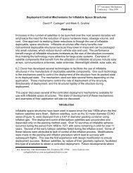
Controlled Deployment System<br />
In conjunction with the development of rigidization<br />
methods, ILC Dover has also developed a number of<br />
deployment techniques to ensure a proper and controlled<br />
deployment of inflatable structures. The purpose for the<br />
controlled deployment system is to (1) keep the deploying<br />
system within a known envelope, (2) improve structural<br />
reliability during deployment by avoiding entanglement<br />
with itself or other components, and (3) minimize shock or<br />
impulse induced to the spacecraft during deployment.<br />
Some of the most promising controlled deployment<br />
devices include:<br />
• Columnation Devices<br />
• Roll-up/Reverse Roll-up Devices<br />
• Internal Compartmentalization<br />
• Break Cords/Peel Flaps<br />
• Becket Loops<br />
Out of these controlled deployment devices the Roll-up<br />
design and the Columnation design are the most<br />
promising for the solar array application. The Roll-up<br />
design is currently under further development at ILC<br />
Dover for flight experiment in the near future. The Roll-up<br />
and the Columnation Devices will be discussed next in<br />
greater detail. The reader is encouraged to consult the<br />
reference documents for more detail.<br />
Roll-up Device<br />
One method of deployment control that has seen wide<br />
application in tubes and struts is the roll-up. This<br />
approach utilizes a rolled inflatable tube with an<br />
embedded mechanism to control its rate of unrolling when<br />
inflation gas is introduced. This is similar to a common<br />
party favor that unfurls when you blow into it. There are<br />
two classes of deployment control used in roll-up devices;<br />
1)mechanisms embedded in the tube itself, and 2)<br />
mechanisms mounted at the end of the tube.<br />
Figure 3 - Roll-up Device (with Membrane)<br />
The second class of deployment control method involves<br />
utilizing a torque mechanism at the end of the tube. An<br />
ILC Dover proprietary ‘Torque Mechanism’ is located in<br />
the end cap to provide resistance to unrolling so that<br />
interim beam stiffness during deployment is achieved.<br />
This approach is simple, reliable, compact, and the roll-up<br />
is a benign packing procedure for rigidizable laminates.<br />
Columnation Devices<br />
The columnation device, Figure 4, provides a deployment<br />
method that when inflated extends axially in a straight<br />
telescopic motion with some degree of beam stiffness.<br />
The inflatable tube is axially collapsed on a short mandrel<br />
in its packed state. The top of the mandrel has a tube<br />
compression feature (seal) that applies some resistance to<br />
axial motion of the tube. Inflation gas is introduced<br />
through the mandrel into the forward end of the tube. As<br />
plug load builds in the inflatable, it overcomes the<br />
frictional resistance and advances the tube. This method<br />
places axial load in the tube wall during deployment,<br />
allowing it to behave as an inflated beam and exhibit<br />
structural stiffness. Several variations of this device,<br />
including inflatable and collapsible mandrels that allow the<br />
packed beam to fit into very small volumes, have been<br />
developed and tested with good results.<br />
Embedded mechanisms include Velcro strips mounted<br />
longitudinally on the tube’s exterior, or constant force<br />
springs mounted to the tube's interior in the same fashion.<br />
Introduction of gas into the tube would separate the Velcro<br />
due to shape change during inflation, or unroll the springs.<br />
Each system provides a calculable value of resistance,<br />
which dictates the internal pressure in the tube. This in<br />
turn dictates the interim beam stiffness of the tube during<br />
deployment, prior to rigidization.<br />
Figure 4 - Columnation Device<br />
3
INFLATABLE SOLAR ARRAYS<br />
The advantages of using inflatable systems technology in<br />
designing a large solar array are reduced stowage volume<br />
and mass, increased specific power (greater than 100<br />
W/kg), and reduced cost over current mechanically<br />
deployed solar arrays. The inflatable solar array is<br />
particularly attractive for missions that demand high power<br />
output with launch vehicle size restrictions. ILC is working<br />
or has developed a number of different solar array<br />
systems for planetary or space use. A few of these<br />
systems are described below.<br />
ST4 INFLATABLE SOLAR ARRAY<br />
The JPL ST4 spacecraft requires high power output arrays<br />
(2 wings at 6 kW per wing) to accomplish the mission of<br />
rendezvous with the Temple 1 comet and landing to<br />
perform scientific measurements. The ST4 inflatable<br />
solar array is a 3-meter by 15-meter solar array capable of<br />
producing 6 kW of power. The array is currently under<br />
development for a shuttle flight experiment in late 2000.<br />
ILC Dover is the prime contractor to JPL for this<br />
experiment, with AEC-Able developing the array blanket<br />
and L’Garde developing the instrumentation. The basic<br />
configuration of the ST4 inflatable solar array, Figure 5,<br />
consists of four major subsystems:<br />
• <strong>Solar</strong> Array Blanket<br />
• Structural Support Components<br />
• Controlled Deployment System<br />
• Inflation System<br />
Top Panel<br />
(Full length)<br />
<strong>Inflatable</strong>/Rigidizable Tube<br />
<strong>Solar</strong><br />
Panels<br />
9.8 ft [3.00 m]<br />
<strong>Solar</strong> Array Blanket<br />
48 ft [14.65 m]<br />
Bottom Panel<br />
(Split)<br />
Figure 5 - ST4 <strong>Inflatable</strong> <strong>Solar</strong> Array<br />
Inflation<br />
System<br />
The configuration of the ST4 solar array is a modular split<br />
blanket style with the deployment tube located on the<br />
array centerline. When stowed, the solar array modules<br />
are accordion-folded. Currently, Sharp’s rigid highefficiency<br />
silicon photovoltaic assemblies are the basic<br />
building blocks for the modular blanket solar array.<br />
Flexible thin film solar cells using amorphous silicon,<br />
copper indium gallium diselenide or other materials hold<br />
great promise to provide even lower cost and lighter<br />
Gimbal<br />
weight photovoltaic modules in similar arrays in the future.<br />
listed in this paper.<br />
Structural Support Components<br />
This subsystem includes the inflatable beam, stowage<br />
panels, plume-offset panels, launch ties, and launch tie<br />
release mechanism. The inflatable beam can be<br />
fabricated from any of the aforementioned rigidization<br />
systems. However, the thermal heating method will be<br />
utilized for the flight experiment.<br />
The purpose of the inflatable beam is to provide a<br />
deployment mechanism and support structure for the solar<br />
array. It is similar in function to the mechanical<br />
deployment truss masts currently utilized on spacecraft.<br />
The beam is located on center of the split blanket and is<br />
stowed by rolling the tube, see Figure 6.<br />
22 <strong>Solar</strong> Panels<br />
Roll-up Tube<br />
118.11” [3000.00 mm]<br />
52.70” [1338.58 mm] TYP.<br />
Launch Ties<br />
Top Panel<br />
22.00” [558.80 mm]<br />
Inflation System<br />
14.00” [355.60 mm]<br />
4.50” [114.30 mm]<br />
Figure 6 - ST4 <strong>Inflatable</strong> <strong>Solar</strong> Array Stowed Configuration<br />
Controlled Deployment System<br />
The ILC roll-up device with the embedded torque<br />
mechanism is the current baseline design for the ST4<br />
inflatable solar array deployment system. When gas is<br />
introduced in the base of the tube, the tube inflates and<br />
begins to unfurl. The torque mechanism provides<br />
resistance to the unrolling action and builds pressure in<br />
the tube at a uniform and constant level. The pressure in<br />
the tube yields a tensile stress in the tube wall, which<br />
provides interim beam stiffness during deployment. The<br />
torque mechanism is attached to the tip spreader plate on<br />
the array, which deploys the array blanket. Guide wires<br />
are also attached to both spreader plates and the blanket<br />
for control of the blanket during deployment.<br />
Inflation System<br />
Inflation systems for the space inflatable structures have<br />
included compressed gas, gas generators, and<br />
sublimation of powders and liquids into gases. Each of<br />
these approaches has its advantages and disadvantages<br />
depending on the specific application. In recent years,<br />
compressed gas systems have become very low mass<br />
and highly reliable, making them the most practical option<br />
for most space inflatable applications. A compressed gas<br />
system is currently baselined for the ST4 inflatable solar<br />
array inflation system.<br />
4
MARS ROVER INFLATABLE SOLAR ARRAY<br />
TELEDESIC INFLATABLE SOLAR ARRAY<br />
The Teledesic program envisions a constellation of 288<br />
satellites in low earth orbit to provide high data rate<br />
communication from anywhere on earth. Original<br />
concepts for the satellite included a pair of 6 kW solar<br />
array, see Figure 7, with a cost target of $100/W in<br />
production. <strong>Inflatable</strong> technology was considered to be a<br />
leading candidate in meeting this goal and was therefore<br />
investigated by the Teledesic team.<br />
JPL is developing several advanced rover vehicles for the<br />
exploration of the Martian surface. Several concepts call<br />
for large deployable solar arrays to meet the power needs<br />
of the rover. One such concept, see Figure 9, utilizes 1.5<br />
meter deployable wheels and an inflatable solar array to<br />
cover vast surface areas in rapid times.<br />
Figure 9 - <strong>Inflatable</strong> Mars Rover Prototype<br />
Figure 7 - Teledesic Satellite<br />
ILC Dover, under contract to Boeing, designed an<br />
inflatable structure to support a 3-meter by 10-meter<br />
rectangular satellite solar array. A full-scale prototype<br />
demonstration unit was also fabricated and used in<br />
deployment trials, see Figure 8.<br />
The Mars Rover <strong>Solar</strong> Array prototype, Figure 10, is a<br />
working full-scale inflatable solar array for rover<br />
application. This prototype is a system that would be<br />
packaged in a small volume for launch and deployed in<br />
situ to collect solar energy. The array is parasol shaped<br />
and consists of four main components: (1) the canopy,<br />
which is the membrane that carries the solar modules; (2)<br />
the inflatable torus; (3) the inflatable column; and (4)<br />
sixteen solar modules. The sixteen (16) Kapton gores (the<br />
canopy) of the solar array are tensioned by a 8.0 cm<br />
(tube) diameter by 150 cm (major) diameter 16-sided<br />
inflatable torus, and supported by a 10.0 cm diameter<br />
inflatable column.<br />
Due to the requirement for multiple deployments, the torus<br />
of the prototype is constructed from a lightweight<br />
aluminized Mylar assembled by pressure sensitive<br />
adhesive tape of the same material. The prototype<br />
inflatable column is fabricated from a laminate of Kapton<br />
and aluminized Mylar. The inflatable torus and column of<br />
the future flight unit will be constructed from thin-walled<br />
aluminum/Kapton laminates or UV cured laminates.<br />
Figure 8 - Teledesic <strong>Inflatable</strong> <strong>Solar</strong> Array<br />
Due to the limited packing volume of the array, the mast<br />
system is designed with a deployment tube, whose only<br />
function is to deploy the array, and two composite<br />
rigidizable tubes to provide structural support after<br />
deployment. This design was also constrained by a<br />
requirement for limiting frontal area in any orientation to<br />
reduce drag during orbital ascent. This requirement<br />
forced the use of a three-tube system rather than a single<br />
multifunctional tube structure. The mast structure is<br />
located on the backside of the array. The deployment<br />
tube uses an inflatable columnation device for controlled<br />
deployment. The two structural tubes are z-folded into a<br />
small compact stowage volume and pulled out during<br />
deployment.<br />
<strong>Solar</strong> cells selected for the prototype array are<br />
manufactured by Iowa Thin Film Technologies Inc. These<br />
modules consist of tandem amorphous silicon (a-Si) solar<br />
cell material deposited on 2 mil thick polyimide. Each<br />
solar module is made of three, 12 volt, 50 mA, solar<br />
panels connected in parallel with a blocking diode. All<br />
three panels and the blocking diode are enclosed inside 5<br />
mil polyester encapsulant. Each module is capable of<br />
generating 12 volt and 150 mA at 1000-watts/m 2 light<br />
intensity with 5% cell efficiency. The Mars solar array<br />
prototype is therefore capable of generating approximately<br />
20 watts of power in a terrestrial environment or 12 watts<br />
in a Martian environment. Further optimization in cell<br />
population pattern, cell efficiency and mass will further<br />
increase specific power to weight ratio.<br />
5
SYNTHETIC APERTURE RADAR ARRAY (SAR)<br />
Figure 10 - Mars Rover <strong>Inflatable</strong> <strong>Solar</strong> Array<br />
POWER SPHERE<br />
ILC Dover together with the Aerospace Corporation<br />
developed concepts for a Power Sphere solar array, which<br />
would enable the use of micro and nano satellites. The<br />
design of the power sphere allows for constant power<br />
generation independent of the sphere’s orientation. The<br />
sphere could be packaged in very small stowage volume<br />
and would deploy and inflate using sublimating powder or<br />
compressed gas. The power sphere would generate in the<br />
neighborhood of 5watss of power with a system mass of<br />
600grams. ILC Dover fabricated a proof of concept unit<br />
for demonstration purposes, Figure 11.<br />
The SAR program was a development effort performed by<br />
ILC Dover for NASA’s JPL to demonstrate the feasibility of<br />
a low mass inflatable Synthetic Aperture Radar Array<br />
Antenna. The prototype system, see Figure 12, was a flat<br />
multiple-layered metalized thin film microstrip array (a<br />
three-membrane assembly) tensioned and supported by<br />
an inflated frame that can be rigidized after deployment.<br />
The size of the full-scale array was a 10-m x 3.3-m<br />
structure. The system was stowed in a rolled-up<br />
configuration on the spacecraft bus, and was deployed in<br />
a controlled manner via inflation gas. The objective of<br />
this program was to develop a functional subscale system<br />
that was less than 2 kg/m 2 of radiating area when<br />
projected to full scale. The subscale prototype met the<br />
requirements and demonstrated the feasibility of the low<br />
mass SAR concept.<br />
Figure 12 - Synthetic Aperture Radar Array<br />
The deployment method and supporting frame concept<br />
used in the SAR could also be used for a flexible blanket<br />
type solar array in future developments. That is, the<br />
membrane assembly of the SAR could be replaced with a<br />
flexible thin film solar cell blanket and the system would<br />
then act as an inflatable solar array.<br />
JPL 3-METER KA-BAND INFLATABLE<br />
REFLECTARRAY<br />
Figure 11 – Power Sphere<br />
RELATED APPLICATIONS<br />
Developments in related applications are producing more<br />
packaging and deployment concepts that are applicable<br />
for deploying future inflatable solar arrays with flexible<br />
thin-film array blankets. Investigations in these projects<br />
are pushing the inflatable technologies forward both in<br />
rigidizable structures and controlled deployment systems.<br />
In conjunction with improvements made in the inflatable<br />
technologies, further advancements in the flexible thinfilm<br />
photovoltaic cells will make these concepts prime<br />
candidates for future inflatable solar arrays. The concepts<br />
discussed below also employed many of the latest<br />
advancements in the inflatable technology.<br />
The 3-Meter Ka-Band Reflectarray program is another<br />
development effort performed by ILC Dover for JPL to<br />
demonstrate the feasibility of super low mass<br />
telecommunication and spaceborne SAR concepts. This<br />
3-Meter prototype, see Figure 13, consists of four major<br />
subassemblies: (1) the membrane assembly; (2) the rigid<br />
frame assembly; (3) the inflatable frame assembly; and<br />
(4) the suspension system.<br />
6
Figure 13 - JPL 3-Meter Ka-Band <strong>Inflatable</strong> Microstrip<br />
Reflectarray<br />
The reflectarray membrane, supplied by JPL and<br />
assembled by ILC, is suspended by a horseshoe shaped<br />
structure assembled from a straight rigid frame assembly<br />
and a U-shaped inflatable frame assembly. The rigid<br />
frame assembly is made from graphite epoxy with<br />
aluminum end caps. The inflatable frame assembly is<br />
fabricated from urethane coated Kevlar to simulate a<br />
rigidizable material in the final application. The<br />
membrane support frame is 25 cm in diameter and the<br />
feed horn support torus is 7.5 cm in diameter. The feed<br />
horn torus is supported by three vertical struts grouped<br />
within 90 degrees of each other. The struts are tapered in<br />
diameter, from the larger diameter of the membrane<br />
support tube to the smaller diameter of the feed horn<br />
torus, to minimize material in the RF path as well as<br />
system mass. One of the critical requirements for this<br />
program is the flatness of the membrane. For this reason<br />
many packaging and deployment concepts were<br />
considered, with the current configuration being the best<br />
for this particular application. Again, similar to the<br />
rectangular frame used for the SAR array, the horseshoe<br />
frame concept could also be used for solar array<br />
deployment.<br />
NGST (ISIS) SUNSHIELD<br />
ILC Dover is working with JPL and GSFC on the NGST<br />
(ISIS) Sunshield program. The goal of the program is to<br />
demonstrate a 1/3-scale model of the Next Generation<br />
Space Telescope (NGST) sunshield. A ½ scale model<br />
has already been demonstrated in 1G and the current<br />
program calls for the 1/3 scale model to be demonstrated<br />
on the shuttle in 2000. The sunshield is a diamond<br />
shaped membrane structure that measures approximately<br />
5 x 11 x 1 meters when deployed. The system consists of<br />
4 layers of membranes that are deployed and supported<br />
by 4 inflatable beams. The membranes, when stowed, are<br />
accordion-folded or “Z” folded into a small packing volume<br />
around the bus structure. The roll-up method for<br />
controlled deployment and the heat cured thermoset<br />
composite laminates are baselined for this demonstration.<br />
The system shown in Figure 14 is a half scale model<br />
deployed at ILC with a gravity negation system attached to<br />
the sunshield.<br />
Figure 14 - NGST Half Scale Sunshield<br />
CONCLUSIONS<br />
<strong>Inflatable</strong> solar array technology continues to mature and<br />
expand the possibilities for large-scale satellite solar<br />
arrays as well as planetary surface arrays for rover use.<br />
<strong>Technology</strong> advancements in inflatable rigidizable<br />
structures and controlled deployment systems, in<br />
conjunction with advancements in solar cell technology<br />
have lead to increases in specific power, reductions in<br />
system cost, and minimization of package volume for<br />
solar arrays. Lab and thermal vacuum chamber<br />
demonstrations of this technology have shown the viability<br />
of the approach. The flight demonstration of the ST4 solar<br />
array will provide the necessary flight heritage to allow the<br />
use of this technology for future deep space and<br />
commercial missions.<br />
CONTACT<br />
Mark S. Grahne<br />
ILC Dover, Inc.<br />
One Moonwalker Road<br />
Frederica, DE 19946<br />
Grahnm@ilcdover.com<br />
302.335.3911x462<br />
302.335.1320 fax<br />
www.ilcdover.com<br />
REFERENCES<br />
1. D.P. Cadogan, M. Grahne, and M. Mikulas, “<strong>Inflatable</strong><br />
Space Structures: A New Paradigm For Space<br />
Structure Design,” IAF-98-I.1.02, 49th International<br />
Astronautical Congress, Melbourne, Australia,<br />
September 28 - October 2, 1998.<br />
2. C. M. Satter and R. E. Freeland, “<strong>Inflatable</strong> Structures<br />
<strong>Technology</strong> Applications and Requirements,” AIAA 95-<br />
3737, AIAA 1995 Space Programs and Technologies<br />
Conference, Huntsville, AL, September 26-28, 1995.<br />
7
3. D.P. Cadogan, R.W. Lingo, and C.R. Sandy, “Proof-<br />
Of-Concept Demonstration Model of the <strong>Inflatable</strong><br />
Roll-Up Synthetic Aperture Radar Array Antenna,” ILC<br />
Dover Final Report for JPL Contract No. 96836,<br />
September 1997.<br />
4. M.C. Lou, V.A. Feria, and J. Huang, “Development of<br />
An <strong>Inflatable</strong> Space Synthetic Aperture Radar,” AIAA<br />
98-2103, 1998.<br />
5. V.A. Feria, M.C. Lou, J. Huang, and S.E. Speer,<br />
“Lightweight Deployable Space Radar <strong>Arrays</strong>,” AIAA<br />
98-1933, 1998<br />
6. J. K. Lin and D. P. Cadogan, “Concept Development,<br />
Design, and Fabrication of an <strong>Inflatable</strong> <strong>Solar</strong> Array<br />
for a Mars Rover Application,” ILC Dover Final Report<br />
for JPL, June 1998.<br />
7. E.S. Fairbanks and M.T. Gates, “Adaptation of Thin-<br />
Film Photovoltaic <strong>Technology</strong> For Use in Space,” 26th<br />
IEEE PVSC, Anaheim, California, 1997.<br />
8. S. Guha, et. al., “Recent Progress in Amorphous<br />
Silicon Alloy Leading to 13% Stable Cell Efficiency,”<br />
26th IEEE PVSC, Anaheim, California, 1997.<br />
9. F. Jeffrey, et. al., “Lightweight, Flexible, Monolithic<br />
Thin-Film Amorphous Silicon Modules on Continuous<br />
Polymer Substrates,” Int. J. <strong>Solar</strong> Energy, 1996, Vol.<br />
18, pp. 205-212.<br />
8