new advances in primerless silicone insulation materials - Team-Logic
new advances in primerless silicone insulation materials - Team-Logic
new advances in primerless silicone insulation materials - Team-Logic

Create successful ePaper yourself
Turn your PDF publications into a flip-book with our unique Google optimized e-Paper software.
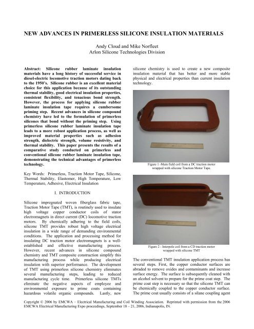
NEW ADVANCES IN PRIMERLESS SILICONE INSULATION MATERIALS<br />
Andy Cloud and Mike Norfleet<br />
Arlon Silicone Technologies Division<br />
Abstract: Silicone rubber lam<strong>in</strong>ate <strong>in</strong>sulation<br />
<strong>materials</strong> have a long history of successful service <strong>in</strong><br />
diesel-electric locomotive traction motors dat<strong>in</strong>g back<br />
to the 1950’s. Silicone rubber is an excellent material<br />
choice for this application because of its outstand<strong>in</strong>g<br />
thermal stability, good electrical <strong>in</strong>sulation properties,<br />
consistent flexibility, and tenacious bond strength.<br />
However, the process for apply<strong>in</strong>g <strong>silicone</strong> rubber<br />
lam<strong>in</strong>ate <strong>in</strong>sulation tape requires a cumbersome<br />
prim<strong>in</strong>g step. Recent <strong>advances</strong> <strong>in</strong> <strong>silicone</strong> compound<br />
chemistry have led to the formulation of <strong>primerless</strong><br />
<strong>silicone</strong>s that bond without the prim<strong>in</strong>g step. Us<strong>in</strong>g<br />
<strong>primerless</strong> <strong>silicone</strong> rubber lam<strong>in</strong>ate <strong>in</strong>sulation tape<br />
leads to a more robust application process, as well as<br />
improved material properties such as adhesion<br />
strength, dielectric strength, volume resistivity, and<br />
thermal stability. This paper presents the results of a<br />
comparative study conducted on <strong>primerless</strong> and<br />
conventional <strong>silicone</strong> rubber lam<strong>in</strong>ate <strong>in</strong>sulation tape,<br />
demonstrat<strong>in</strong>g the technical advantages of <strong>primerless</strong><br />
technology.<br />
Key Words: Primerless, Traction Motor Tape, Silicone,<br />
Thermal Stability, Elastomer, High Temperature, Low<br />
Temperature, Adhesive, Electrical Insulation<br />
<strong>silicone</strong> chemistry is used to create a <strong>new</strong> composite<br />
<strong>in</strong>sulation material that has better and more stable<br />
physical and electrical properties than current <strong>in</strong>sulation<br />
technology.<br />
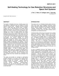
Figure 1 -Ma<strong>in</strong> field coil from a DC traction motor<br />
wrapped with <strong>silicone</strong> Traction Motor Tape.<br />
I. INTRODUCTION<br />
Silicone impregnated woven fiberglass fabric tape,<br />
Traction Motor Tape (TMT), is rout<strong>in</strong>ely used to <strong>in</strong>sulate<br />
high voltage copper conductor coils of stator<br />
electromagnets <strong>in</strong> direct current (DC) locomotive traction<br />
motors. By chemically adher<strong>in</strong>g to the field coils,<br />
<strong>silicone</strong> TMT provides robust high voltage electrical<br />
<strong>in</strong>sulation <strong>in</strong> a wide range of demand<strong>in</strong>g environmental<br />
conditions. The application and process<strong>in</strong>g method for<br />
<strong>in</strong>sulat<strong>in</strong>g DC traction motor electromagnets is a wellestablished<br />
and effective manufactur<strong>in</strong>g process.<br />
However, recent <strong>advances</strong> <strong>in</strong> <strong>silicone</strong> compound<br />
chemistry and TMT composite construction simplify this<br />
manufactur<strong>in</strong>g process while produc<strong>in</strong>g electrical<br />
<strong>in</strong>sulation with superior performance. The development<br />
of TMT us<strong>in</strong>g <strong>primerless</strong> <strong>silicone</strong> chemistry elim<strong>in</strong>ates<br />
several manufactur<strong>in</strong>g steps, lead<strong>in</strong>g to reduced<br />
manufactur<strong>in</strong>g cycle time. Primerless <strong>silicone</strong> TMTs<br />
elim<strong>in</strong>ate the negative aspects of employee and<br />
environmental exposure to prime coats conta<strong>in</strong><strong>in</strong>g<br />
hazardous volatile organic compounds. Lastly, <strong>new</strong><br />
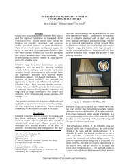
Figure 2 - Interpole coil from a CD traction motor<br />
wrapped with <strong>silicone</strong> TMT<br />
The conventional TMT <strong>in</strong>sulation application process has<br />
several steps. First, the copper conductor surfaces are<br />
abraded to remove oxides and contam<strong>in</strong>ants and <strong>in</strong>crease<br />
surface energy. The surface is subsequently cleaned with<br />
an alcohol solvent to prepare for the prime coat step. The<br />
prime coat step is necessary so that the <strong>silicone</strong> TMT can<br />
be chemically coupled to the copper conductor surface.<br />
The prime coat usually consists of a silane coupl<strong>in</strong>g agent<br />
Copyright © 2006 by EMCWA – Electrical Manufactur<strong>in</strong>g and Coil W<strong>in</strong>d<strong>in</strong>g Association. Repr<strong>in</strong>ted with permission from the 2006<br />
EMCWA Electrical Manufactur<strong>in</strong>g Expo proceed<strong>in</strong>gs, September 18 – 21, 2006, Indianapolis, IN.
system dispersed <strong>in</strong> a solvent carrier. A th<strong>in</strong> layer of<br />
primer is applied to the copper conductor. The control of<br />
primer quantity is critical, because both underprim<strong>in</strong>g and<br />
overprim<strong>in</strong>g can lead to poor TMT adhesion. The primed<br />
conductor must stand for a significant dwell time prior to<br />
TMT application to allow solvent flash and <strong>in</strong>itiation of<br />
coupl<strong>in</strong>g k<strong>in</strong>etics. The <strong>silicone</strong> TMT is then applied by<br />
hand or <strong>in</strong> an automated process utiliz<strong>in</strong>g tape reels for<br />
coil radii and sheet goods for coil faces. The wrapped<br />
coil is then placed <strong>in</strong> lam<strong>in</strong>at<strong>in</strong>g equipment where heat<br />
and pressure are applied to chemically crossl<strong>in</strong>k and<br />
couple the <strong>silicone</strong> TMT <strong>in</strong>sulation to the copper<br />
conductor surface. Lastly, the coil is post-baked <strong>in</strong> order<br />
to complete the coupl<strong>in</strong>g process, remove organic<br />
peroxide by-products used to <strong>in</strong>itiate <strong>silicone</strong><br />
crossl<strong>in</strong>k<strong>in</strong>g, and stabilize the <strong>silicone</strong> matrix by removal<br />
of low molecular weight siloxanes.<br />
Utilization of <strong>primerless</strong> <strong>silicone</strong> chemistry allows for the<br />
elim<strong>in</strong>ation of the prim<strong>in</strong>g process to couple the <strong>silicone</strong><br />
TMT to the copper conductors. As a result, cycle time is<br />
reduced significantly. An additional benefit is that the<br />
chance for defectively primed coils is elim<strong>in</strong>ated. Us<strong>in</strong>g<br />
conventional <strong>silicone</strong> TMT, defects can form as blisters<br />
and delam<strong>in</strong>ation at the <strong>silicone</strong> TMT and copper<br />
conductor <strong>in</strong>terface, often requir<strong>in</strong>g subsequent repair<br />
steps or even complete <strong>in</strong>sulation rework.<br />
Traditional silane primer chemistry presents personnel<br />
exposure and environmental impact issues that must be<br />
managed. Hazardous conditions are managed by<br />
regulatory personnel to ensure employee safety and<br />
environmental compliance. However, <strong>in</strong>dustrial hazards<br />
can be mitigated and even elim<strong>in</strong>ated through <strong>new</strong><br />
technologies such as <strong>primerless</strong> <strong>silicone</strong> TMT. Because<br />
prime coat <strong>materials</strong> are elim<strong>in</strong>ated with <strong>primerless</strong><br />
technology, the volatile organic compounds used as<br />
solvent carriers are also elim<strong>in</strong>ated. While solvent carrier<br />
types can differ given the variety of commercial grade<br />
prime coat <strong>materials</strong>, <strong>in</strong> general they are highly<br />
flammable liquids with extremely low flash po<strong>in</strong>ts.<br />
Additionally, these solvent carriers can cause sk<strong>in</strong>, eye,<br />
and respiratory irritation through acute toxicity and<br />
possibly major organ damage through chronic exposure if<br />
not carefully managed. Industrial management and<br />
regulation of these carrier <strong>materials</strong> is required through<br />
OSHA and local govern<strong>in</strong>g bodies. Oversight of these<br />
hazardous components <strong>in</strong> today’s electromagnetic coil<br />
<strong>in</strong>sulation processes is no longer necessary because<br />
solvent carrier functionality has been elim<strong>in</strong>ated with<br />
<strong>primerless</strong> <strong>silicone</strong>.<br />
Besides process simplification and reduction of hazardous<br />
components, <strong>primerless</strong> <strong>silicone</strong> TMT technology also<br />
leads to an improvement <strong>in</strong> electrical <strong>in</strong>sulation on many<br />
fronts. Key properties for <strong>silicone</strong> TMT <strong>in</strong>sulation<br />
<strong>in</strong>clude excellent adhesion strength to copper conductor<br />
surfaces, high voltage dielectric breakdown strength,<br />
excellent volume resistivity, and stability of these<br />
properties when subjected to elevated operat<strong>in</strong>g<br />
temperatures and hostile environmental conditions.<br />
Adhesive strength of the <strong>silicone</strong> TMT to the copper<br />
conductor dur<strong>in</strong>g traction motor operation is paramount<br />
because <strong>in</strong>sulation delam<strong>in</strong>ation can lead to voltage arc<strong>in</strong>g<br />
and potential <strong>in</strong>sulation damage. High dielectric<br />
breakdown strength is necessary to ensure that the<br />
electromagnetic coil’s conductive path is ma<strong>in</strong>ta<strong>in</strong>ed so<br />
that motor power and longevity are assured and<br />
ma<strong>in</strong>ta<strong>in</strong>ed. High volume resistivity assures that leakage<br />
currents, especially those <strong>in</strong>duced by contam<strong>in</strong>ation and<br />
moisture, are mitigated. Lastly, these specific properties<br />
must be ma<strong>in</strong>ta<strong>in</strong>ed over thousands of hours of high<br />
temperature motor operation where thermal/mechanical<br />
load from both thermal cycl<strong>in</strong>g and dynamic vibration<br />
encountered <strong>in</strong> mobile motors stra<strong>in</strong> electrical <strong>in</strong>sulation<br />
systems. Primerless <strong>silicone</strong> technology coupled with a<br />
highly electrically <strong>in</strong>sulative fiberglass fabric weave<br />
configuration produces a superior TMT compared to that<br />
of conventional TMT material <strong>in</strong> all property categories.<br />
The key to the technological improvement is the stability<br />
of these properties versus conventional technology after<br />
thermal stress. Stability is anchored by the <strong>silicone</strong>’s<br />
ability to resist depolymerization (<strong>in</strong>termolecular and<br />
<strong>in</strong>tramolecular cha<strong>in</strong> scission) and oxidative<br />
embrittlement. Primerless <strong>silicone</strong> offers superior<br />
resistance to both thermal degradation mechanisms to<br />
ensure that key material requirements rema<strong>in</strong> <strong>in</strong>tact over<br />
the motor service life.<br />
II. DISCUSSION<br />
A. Manufactur<strong>in</strong>g cycle time reduction and defect<br />
reduction<br />
The use of Primerless TMT tape versus Conventional tape<br />
offers the elim<strong>in</strong>ation of major steps <strong>in</strong> the electromagnet<br />
coil <strong>in</strong>sulation manufactur<strong>in</strong>g process. The targeted step<br />
for elim<strong>in</strong>ation is the copper conductor prime coat<br />
application step.<br />
Prim<strong>in</strong>g copper conductor surfaces with a commercial<br />
grade primer is necessary to adhere conventional TMT<br />
<strong>in</strong>sulation <strong>materials</strong>. The prime coat is generally an<br />
organosilane coupl<strong>in</strong>g agent dispersed <strong>in</strong> an alcohol or<br />
hydrocarbon solvent. The silane’s general molecular<br />
structure is an organofunctional group and three alkoxy<br />
hydrolyzable groups configured around a silicon atom.<br />
The commercial grade silanes are generally applied to the<br />
copper conductors via brush application but can also be<br />
applied by spray or dip. Once the primer is applied the<br />
organosilane undergoes four steps so that a coupl<strong>in</strong>g layer<br />
between the organic pendant groups of the <strong>silicone</strong><br />
Copyright © 2006 by EMCWA – Electrical Manufactur<strong>in</strong>g and Coil W<strong>in</strong>d<strong>in</strong>g Association. Repr<strong>in</strong>ted with permission from the 2006<br />
EMCWA Electrical Manufactur<strong>in</strong>g Expo proceed<strong>in</strong>gs, September 18 – 21, 2006, Indianapolis, IN.
polymer and the hydroxyl groups of the copper conductor<br />
surface can be chemically adhered.<br />
Step 1: The alkoxy groups hydrolyze via surface<br />
moisture and atmospheric moisture as the solvent carrier<br />
evaporates<br />
Step 2: Condensation <strong>in</strong>to small oligomers occurs<br />
Step 3: The small oligomers form hydrogen bonds with<br />
the hydroxyl groups of the copper substrate.<br />
Step 4: Covalent bond formation occurs between the<br />
organofunctional reactive group of the organosilane and<br />
the <strong>silicone</strong> organic pendant group and between the<br />
hydrolyzed groups of the organosilane and the copper<br />
surface to couple the <strong>silicone</strong> to the copper [1] (See<br />
Figure 3)<br />
Primerless <strong>silicone</strong> technology elim<strong>in</strong>ates steps 1 through<br />
4 from the application process. The coil surfaces can be<br />
simply cleaned, wrapped with <strong>primerless</strong> TMT <strong>in</strong>sulation,<br />
vulcanized under pressure at elevated temperatures, and<br />
then post-cured. The prim<strong>in</strong>g step is completely avoided<br />
for faster product throughput.<br />
Remov<strong>in</strong>g the prim<strong>in</strong>g step <strong>in</strong> the application process of<br />
<strong>silicone</strong> TMT application also creates a more robust<br />
manufactur<strong>in</strong>g process by elim<strong>in</strong>at<strong>in</strong>g potential for defects<br />
caused by over and under prim<strong>in</strong>g. Most commercial<br />
grade primers are applied <strong>in</strong> a very th<strong>in</strong> layer so that a<br />
molecular layer of coupl<strong>in</strong>g agent rema<strong>in</strong>s on the copper<br />
conductor surface after the carrier evaporates. Because<br />
the dried primers are difficult to see, there is a chance that<br />
the copper conductor surface will be underprimed, which<br />
ultimately leads to delam<strong>in</strong>ation of the TMT <strong>in</strong>sulation.<br />
However, most problems with silane prim<strong>in</strong>g occur from<br />
overprim<strong>in</strong>g. When a copper conductor surface has been<br />
overprimed the coupl<strong>in</strong>g agent tends to pool and<br />
accelerated condensation occurs. Overprimed surfaces<br />
usually have a cloudy appearance to them because the<br />
organosilane has started to precipitate. In this scenario,<br />
the prime coat will not bond effectively as the condensed<br />
oligomers are not adhered well to the copper substrate<br />
once aga<strong>in</strong> lead<strong>in</strong>g to possible delam<strong>in</strong>ation of TMT<br />
<strong>in</strong>sulation.<br />
Figure 3 [2]<br />
Not all copper conductor surface prime coats are<br />
organosilanes, but even with non-silane commercial grade<br />
prime coats it is difficult to guarantee prime coat<br />
consistency from operator to operator.<br />
B. Employee and Environmental Safety Improvements<br />
Health and safety of operators are a pr<strong>in</strong>cipal priorities <strong>in</strong><br />
manufactur<strong>in</strong>g along with environmental stewardship.<br />
The carriers or the volatile organic content for<br />
organosilane prime coats and even non-silane prime coats<br />
must be monitored for employee safety. Most carriers<br />
present a fire hazard as they have low flash po<strong>in</strong>ts well<br />
below room temperature coupled with high flammability.<br />
OSHA also regulates employee exposure to hazardous<br />
volatile organic compounds such as methanol and<br />
naphtha. The permissible exposure limits (PEL) as a time<br />
Copyright © 2006 by EMCWA – Electrical Manufactur<strong>in</strong>g and Coil W<strong>in</strong>d<strong>in</strong>g Association. Repr<strong>in</strong>ted with permission from the 2006<br />
EMCWA Electrical Manufactur<strong>in</strong>g Expo proceed<strong>in</strong>gs, September 18 – 21, 2006, Indianapolis, IN.
weighted average for exposure is 200 ppm and 500 ppm<br />
respectively for these commonly used prime coat<br />
carriers. [3] Adequate exhaust is recommended for both<br />
<strong>materials</strong> to keep airborne concentrations below the<br />
PEL. Both carriers may also cause sk<strong>in</strong>, eye, respiratory,<br />
and digestive tract irritation through acute exposure.<br />
Chronic or high level exposure to methanol may lead to<br />
kidney, eye, and central nervous system damage while<br />
chronic exposure to naphtha may lead to dermatitis and<br />
central nervous system depression. [4,5] Lastly, local<br />
government agencies may regulate fugitive release of<br />
these volatile organic compounds.<br />
C. Comparative Analysis (Primerless TMT vs.<br />
Conventional TMT)<br />
1. Initial Key Properties<br />
The follow<strong>in</strong>g table compares Primerless and<br />
conventional <strong>silicone</strong> traction motor tape <strong>in</strong>sulation,<br />
clearly demonstrat<strong>in</strong>g adhesion and volume resistivity<br />
advantages for <strong>primerless</strong> TMT.<br />
Property Primerless Conventional<br />
Dielectric Breakdown<br />
Strength<br />
788 VPM 838 VPM<br />
S1 to S2 Adhesion<br />
Strength<br />
10.9 ppiw 6.2 ppiw<br />
S2 to Copper Adhesion<br />
Strength<br />
10.7 ppiw 5.7 ppiw<br />
Insulated Interpole<br />
Volume Resistivity<br />
>50 GΩ 13.5 MΩ<br />
Table 1<br />
Dielectric breakdown specimens were prepared <strong>in</strong> a<br />
heated platen press under 50 psi and then post cured for<br />
two hours at 204°C <strong>in</strong> a mechanically circulated oven.<br />
The specimens were tested for dielectric breakdown<br />
strength accord<strong>in</strong>g to Arlon’s SQA-TMS-020 work<br />
<strong>in</strong>struction. This work <strong>in</strong>struction references ASTM<br />
D149, which covers dielectric breakdown voltage and<br />
electric strength of solid electrical <strong>in</strong>sulation <strong>materials</strong> at<br />
commercial power frequencies.<br />
The Side 1 to Side 2 (S1 to S2) adhesive strength coupon<br />
specimens were prepared to represent the over-wrapp<strong>in</strong>g<br />
of TMT dur<strong>in</strong>g <strong>in</strong>sulation of electromagnet copper coils.<br />
Test samples were prepared <strong>in</strong> a heated platen press under<br />
50 psi of lam<strong>in</strong>ation pressure accord<strong>in</strong>g to Arlon’s SQA-<br />
TMS-011 work <strong>in</strong>struction. The test pull rate was<br />
2”/m<strong>in</strong>ute. This work <strong>in</strong>struction references ASTM<br />
D1876, which covers peel resistance of adhesives (T-peel<br />
test). The specimens were additionally post-cured for two<br />
hours at 204°C <strong>in</strong> a mechanically circulated oven before<br />
adhesion strength was measured.<br />
The S2 to copper adhesion strength coupons were also<br />
evaluated <strong>in</strong> a similar manner. However, for the<br />
Conventional TMT to copper specimens, the copper<br />
surface was <strong>in</strong>itially abraded with a scotchbrite pad,<br />
cleaned with Isopropyl Alcohol (IPA), and then primed<br />
with a 2:1 volumetric ratio of IPA:Chemlok 607 primer<br />
and allowed to dry for 30 m<strong>in</strong>utes at 50% RH at 23°C.<br />
The volume resistivity was determ<strong>in</strong>ed by a novel wet<br />
high potential test us<strong>in</strong>g an <strong>in</strong>sulated DC traction motor<br />
<strong>in</strong>terpole electromagnet copper coil. Coils wrapped with<br />
Primerless TMT were unprimed and coils wrapped with<br />
Conventional TMT were primed for adhesion. The<br />
radius area of each coil was wrapped with one-<strong>in</strong>ch wide<br />
tape and the straight sections used two layers of wider roll<br />
stock. Coils were then wrapped with polyester film for<br />
cleanl<strong>in</strong>ess and m<strong>in</strong>or abrasion protection. The coils were<br />
<strong>in</strong>serted <strong>in</strong>to the vulcanization fixture and lam<strong>in</strong>ated<br />
under pressure and <strong>in</strong>ductive heat<strong>in</strong>g. The lam<strong>in</strong>ated coils<br />
were subsequently post cured to stabilize the TMT<br />
<strong>in</strong>sulation. The coils were <strong>in</strong>serted <strong>in</strong>to a water bath and a<br />
5000 volt potential was applied to the copper conductor.<br />
The electrical resistance through the TMT <strong>in</strong>sulation was<br />
measured.<br />
The <strong>in</strong>itial key property comparison presents a quick look<br />
at the two TMT <strong>materials</strong>. The <strong>materials</strong> offer similar<br />
dielectric breakdown strength and the <strong>primerless</strong> <strong>silicone</strong><br />
compound exhibits much stronger adhesion properties.<br />
The high volume resistivity performance of the <strong>primerless</strong><br />
TMT is attributed to the excellent copper to <strong>silicone</strong><br />
adhesion and the quality composite structure of the<br />
<strong>silicone</strong> impregnated fiberglass fabric of the <strong>primerless</strong><br />
TMT material.<br />
2. Reversion Resistance – theoretical understand<strong>in</strong>g of<br />
key property degradation result<strong>in</strong>g from <strong>silicone</strong><br />
depolymerization.<br />
Both the <strong>primerless</strong> and the conventional TMT<br />
compounds were tested for reversion resistance <strong>in</strong> a<br />
Monsanto R-100 Rheometer per Arlon’s SQA-TMS-030<br />
Work Instruction. Uncured rubber compound samples<br />
were placed <strong>in</strong> the Rheometer at 204°C and monitored for<br />
polymer reversion over a two hour period. The degree of<br />
reversion is determ<strong>in</strong>ed by the percentage change <strong>in</strong><br />
rheometer torque over a two hour test period from the<br />
maximum torque value achieved <strong>in</strong> that same two hour<br />
test period. Polymer reversion is measured and correlated<br />
to a percent loss of Rheometer torque.<br />
Copyright © 2006 by EMCWA – Electrical Manufactur<strong>in</strong>g and Coil W<strong>in</strong>d<strong>in</strong>g Association. Repr<strong>in</strong>ted with permission from the 2006<br />
EMCWA Electrical Manufactur<strong>in</strong>g Expo proceed<strong>in</strong>gs, September 18 – 21, 2006, Indianapolis, IN.
Rheometer Reversion Resistance<br />
Percent torque<br />
Compound<br />
change from<br />
maximum torque<br />
Primerless TMT compound + 5.4%<br />
Conventional TMT compound - 61.0 %<br />
Table 2<br />
Reversion of the <strong>silicone</strong> polymer occurs <strong>in</strong> the absence<br />
of air at elevated temperatures. Reversion results <strong>in</strong> the<br />
depolymerization of high polymer <strong>in</strong>to low molecular<br />
weight siloxanes and degradation of all key properties of<br />
traction motor <strong>in</strong>sulation. Results of polymer reversion <strong>in</strong><br />
TMT are <strong>in</strong>sulation delam<strong>in</strong>ation and loss of electrical<br />
<strong>in</strong>sulat<strong>in</strong>g features. Silicone depolymerization occurs as<br />
Dvornic expla<strong>in</strong>s, … by either <strong>in</strong>ter- or <strong>in</strong>tra-molecular<br />
siloxane redistribution reactions that occur randomly<br />
between the siloxane bonds located <strong>in</strong>side the polymer<br />
cha<strong>in</strong>s and proceed through the formation of <strong>in</strong>termediate<br />
four-center states yield<strong>in</strong>g volatile cyclic siloxanes.… [6]<br />
As <strong>in</strong>dicated, this process leads to random scission of the<br />
high polymer and an overall reduction of polymer<br />
molecular weight. [7] Depolymerization <strong>in</strong> the Arlon<br />
Reversion Resistance Test method is additionally<br />
aggravated by the presence of acidic peroxide by-products<br />
rema<strong>in</strong><strong>in</strong>g <strong>in</strong> the polymer and is considered a worst case<br />
scenario. Dvornic concludes that, …,the presence of<br />
ionic impurities <strong>in</strong> polysiloxanes may completely ru<strong>in</strong> one<br />
of the most characteristic and desirable properties of these<br />
polymers: their high temperature stability, and that is<br />
why only well purified samples (without even trace<br />
amounts of acidic or basic impurities, <strong>in</strong>clud<strong>in</strong>g left-over<br />
polymerization <strong>in</strong>itiators) should be considered for high<br />
temperature applications. [8]<br />
temperatures, atmospheric oxygen has a natural tendency<br />
to bond with silicon atoms to form silica. [9] The<br />
thermo-oxidative degradation process of <strong>silicone</strong> is a slow<br />
process, beg<strong>in</strong>n<strong>in</strong>g with damage to the polymer through<br />
stripp<strong>in</strong>g of pendant groups and eventually lead<strong>in</strong>g to the<br />
onset of excessive polymer cha<strong>in</strong> crossl<strong>in</strong>k<strong>in</strong>g coupled<br />
with the formation of pure silica. [10] This degradation<br />
process can translate <strong>in</strong>to a loss of polymer flexibility<br />
which leads to the onset of <strong>in</strong>sulation micro-crack<strong>in</strong>g,<br />
especially when subjected to vibration or<br />
thermal/mechanical load. Dvornic summarizes, “When<br />
used <strong>in</strong> air, polysiloxanes normally reta<strong>in</strong> their flexibility<br />
for thousands of hours at temperatures of up to about<br />
200°C, or for several hours at 220°C. The loss of<br />
flexibility marks the onset of cross-l<strong>in</strong>k<strong>in</strong>g reactions,<br />
which prevents or greatly reduce the loss <strong>in</strong> polymer<br />
molecular weight and formation of volatile degradation<br />
products at these temperatures. Hence, <strong>in</strong> contrast to<br />
many organic counterparts, polysiloxanes do not abruptly<br />
deteriorate at elevated temperatures <strong>in</strong> air, but <strong>in</strong>stead<br />
they undergo a gradual reduction of mechanical properties<br />
over a period of time.” [11]<br />
In an effort to compare the thermo-oxidative stability of<br />
<strong>primerless</strong> TMT to conventional TMT, the <strong>silicone</strong><br />
impregnated woven fabrics were subjected to several<br />
short term accelerated thermal ag<strong>in</strong>g periods with<br />
dielectric breakdown as the response. The specimens<br />
were prepared as <strong>in</strong>, C. Comparative Analysis<br />
(Primerless TMT vs. Conventional TMT) 1. Initial Key<br />
Properties, and then subjected to the follow<strong>in</strong>g short term<br />
thermal ag<strong>in</strong>g periods: 1. 48 hours at 320°C; 2. 96 hours<br />
at 300°C; 3. 168 hours at 275°C; and 4. 336 hours at<br />
250°C. Dielectric Breakdown strength was measured<br />
after each thermal ag<strong>in</strong>g periods. See results <strong>in</strong> Figure 2<br />
As shown <strong>in</strong> Table 2 the <strong>primerless</strong> TMT compound<br />
exhibits far superior reversion resistance when compared<br />
to the conventional TMT compound. Polymer reversion<br />
is a well-known degradation process that can lead to TMT<br />
<strong>in</strong>sulation delam<strong>in</strong>ation and loss of electrical <strong>in</strong>sulat<strong>in</strong>g<br />
functionality. Excellent reversion resistance leads to<br />
stability of <strong>in</strong>-service traction motor <strong>in</strong>sulation <strong>in</strong> terms of<br />
all of the key properties because the <strong>silicone</strong> polymer is<br />
resistant to this type of thermal degradation.<br />
3. Thermo-oxidative stability – key property degradation<br />
result<strong>in</strong>g from <strong>silicone</strong> oxidation.<br />
a. Dielectric Breakdown Strength Stability<br />
Dielectric Breakdown Strength (VPM)<br />
1000<br />
900<br />
800<br />
700<br />
600<br />
500<br />
400<br />
300<br />
200<br />
100<br />
0<br />
Dielectric Breakdown Strength<br />
(Thermo-oxidative Stability)<br />
2hr PC 204C 48hr @ 320C 96hr @ 300C 168hr @ 275C 336hr @ 250C<br />
Thermal Ag<strong>in</strong>g Period<br />
Figure 2<br />
Conventional TMT<br />
Primerless TMT<br />
The other component of polymer stability under long term<br />
thermal load is the degree of thermo-oxidative resistance.<br />
Thermo-oxidative degradation is a result of polymer<br />
exposure to air or oxygen at elevated temperatures.<br />
Dur<strong>in</strong>g TMT <strong>in</strong>-service exposure to air at high operational<br />
The results clearly demonstrate that aggressive short term<br />
thermal cycles cause aggressive crossl<strong>in</strong>k<strong>in</strong>g and microcrack<strong>in</strong>g<br />
of the conventional TMT lead<strong>in</strong>g to a near 50%<br />
reduction <strong>in</strong> dielectric breakdown strength for all ag<strong>in</strong>g<br />
cycles. Comparatively, the <strong>primerless</strong> TMT shows clear<br />
Copyright © 2006 by EMCWA – Electrical Manufactur<strong>in</strong>g and Coil W<strong>in</strong>d<strong>in</strong>g Association. Repr<strong>in</strong>ted with permission from the 2006<br />
EMCWA Electrical Manufactur<strong>in</strong>g Expo proceed<strong>in</strong>gs, September 18 – 21, 2006, Indianapolis, IN.
signs of thermo-oxidative stability <strong>in</strong> all short term<br />
thermal cycles. The <strong>primerless</strong> TMT does show signs of<br />
some excessive crossl<strong>in</strong>k<strong>in</strong>g and loss of elasticity through<br />
a slight <strong>in</strong>crease <strong>in</strong> dielectric breakdown strength after<br />
each thermal cycle, but clearly the thermo-oxidative<br />
process is retarded and degradation rema<strong>in</strong>s <strong>in</strong> check.<br />
It is noted that short term accelerated thermal ag<strong>in</strong>g cycles<br />
are a good comparative tool but not <strong>in</strong>dicative of actual<br />
<strong>in</strong>-service material functionality. However, the<br />
temperatures chosen are representative of a typical<br />
Underwriters Laboratories accelerated ag<strong>in</strong>g study for<br />
<strong>silicone</strong>s to determ<strong>in</strong>e long term estimates of thermooxidative<br />
stability. Such accelerated tests are generally<br />
extended out to 2000 hours to give a more complete<br />
picture of material stability <strong>in</strong> service.<br />
b. S1 to S2 Adhesion Strength Stability<br />
In addition to dielectric breakdown strength, S1 to S2<br />
adhesion strength of both the <strong>primerless</strong> TMT and a<br />
conventional tape were compared after similar short term<br />
thermo-oxidative cycles. Adhesion coupon specimens<br />
were prepared as <strong>in</strong>, C. Comparative Analysis<br />
(Primerless TMT vs. Conventional TMT) 1. Initial Key<br />
Properties, and then subjected to the follow<strong>in</strong>g short term<br />
thermal ag<strong>in</strong>g periods: 1. 48 hours at 320°C; 2. 96 hours<br />
at 300°C; 3. 168 hours at 275°C; and 4. 336 hours at<br />
250°C. Adhesion strength was measured after each<br />
thermal cycle. See Results <strong>in</strong> Figure 3.<br />
Adhesion strength (ppiw)<br />
11.0<br />
10.0<br />
9.0<br />
8.0<br />
7.0<br />
6.0<br />
5.0<br />
4.0<br />
3.0<br />
2.0<br />
1.0<br />
0.0<br />
S1 to S2 Adhesion Strength<br />
(Thermo-oxidative Stability)<br />
2hr PC 204C 48hr @ 320C 96hr @ 300C 168hr @ 275C 336hr @ 250C<br />
Thermal Ag<strong>in</strong>g Period<br />
Figure 3<br />
Conventional TMT<br />
Primerless TMT<br />
Both the <strong>primerless</strong> and the conventional TMT bond<br />
strength values show dramatic reduction of adhesive<br />
strength <strong>in</strong> each of the elevated thermal cycl<strong>in</strong>g periods.<br />
This is a clear <strong>in</strong>dication of thermo-oxidative polymer<br />
degradation and an obvious loss of polymer elasticity. As<br />
expected, the higher temperature cycles produce the<br />
greatest amount of adhesion degradation. However, while<br />
the conventional TMT adhesion strength appears to show<br />
a complete loss <strong>in</strong> elastic properties required for good<br />
adhesion, the <strong>primerless</strong> TMT still ma<strong>in</strong>ta<strong>in</strong>s enough<br />
elasticity and subsequent adhesion strength to effectively<br />
rema<strong>in</strong> <strong>in</strong>tact as an <strong>in</strong>sulation medium. Advances <strong>in</strong><br />
<strong>silicone</strong> chemistry have added thermo-oxidative stability<br />
to the <strong>primerless</strong> TMT compound.<br />
c. S2 to Copper Adhesion Strength Stability<br />
The thermo-oxidative adhesion strength stability<br />
comparison of TMT lam<strong>in</strong>ated to a copper conductor<br />
surface was approached us<strong>in</strong>g a unique thermal cycl<strong>in</strong>g<br />
methodology. The high temperatures <strong>in</strong> the short term<br />
accelerated ag<strong>in</strong>g tests tend to produce the formation of<br />
Cu 2 O, Cu3O2, and CuO copper oxide layers on the<br />
copper adhesion coupon specimens. The layer readily<br />
delam<strong>in</strong>ates from the adhesion coupon specimen<br />
render<strong>in</strong>g comparative T-peel adhesion test results<br />
unreliable. So, the TMT tape to copper conductor<br />
adhesion strength thermo-oxidative stability was<br />
compared utiliz<strong>in</strong>g low to high temperature thermal<br />
cycl<strong>in</strong>g.<br />
The S2 to copper adhesion strength coupon specimens<br />
were prepared as <strong>in</strong>, C. Comparative Analysis<br />
(Primerless TMT vs. Conventional TMT) 1. Initial Key<br />
Properties. Ply adhesion samples were tested for<br />
adhesion strength after 25, 50, and 75 thermal shock<br />
cycles. One thermal shock cycle is def<strong>in</strong>ed as ramp<strong>in</strong>g<br />
from ~0°C to 204°C <strong>in</strong> 180 seconds <strong>in</strong> a mechanically<br />
circulat<strong>in</strong>g convection oven followed by a 30 second cool<br />
down period <strong>in</strong> ice water to approximately 0°C. This<br />
thermal shock cycle not only evaluates potential<br />
degradation through thermo-oxidative processes but also<br />
evaluates the TMT under thermal/mechanical load<br />
<strong>in</strong>duced stress and stra<strong>in</strong> as would be seen <strong>in</strong> an actual<br />
motor ramp<strong>in</strong>g to high operat<strong>in</strong>g temperatures <strong>in</strong> a cold<br />
field environment.<br />
Bond Strength (ppiw)<br />
12<br />
10<br />
8<br />
6<br />
4<br />
2<br />
0<br />
S2 to Copper Adhesion Strength<br />
(Thermo-oxidative Stability and Thermal/Mechanical Load<strong>in</strong>g via Thermal Shock)<br />
0 10 20 30 40 50 60 70 80<br />
Number of Thermal Shock Cycles<br />
Figure 4<br />
Conventional TMT<br />
Primerless TMT<br />
As shown <strong>in</strong> figure 4, both <strong>primerless</strong> and conventional<br />
<strong>silicone</strong> TMT <strong>materials</strong> are able to absorb the<br />
thermal/mechanical load and resist thermo-oxidative<br />
degradation <strong>in</strong> this test<strong>in</strong>g method. The adhesion strength<br />
of the <strong>silicone</strong> rema<strong>in</strong>s <strong>in</strong> tact after 75 thermal shock<br />
cycles with a negligible loss <strong>in</strong> S2 to copper adhesion.<br />
Primerless TMT reta<strong>in</strong>s the S2 to copper adhesion<br />
Copyright © 2006 by EMCWA – Electrical Manufactur<strong>in</strong>g and Coil W<strong>in</strong>d<strong>in</strong>g Association. Repr<strong>in</strong>ted with permission from the 2006<br />
EMCWA Electrical Manufactur<strong>in</strong>g Expo proceed<strong>in</strong>gs, September 18 – 21, 2006, Indianapolis, IN.
superiority throughout the test<strong>in</strong>g. This test exemplifies<br />
the benefits of <strong>silicone</strong>s as an <strong>in</strong>sulation medium <strong>in</strong><br />
hostile environments.<br />
III. CONCLUSIONS<br />
Primerless <strong>silicone</strong> TMT presents a better overall coil<br />
<strong>in</strong>sulation solution than conventional <strong>silicone</strong> TMT.<br />
Primerless <strong>materials</strong> allow the coil assembler to simplify<br />
the <strong>in</strong>sulation application process significantly while<br />
allow<strong>in</strong>g the elim<strong>in</strong>ation of process aids that are<br />
hazardous to personnel and the environment.<br />
Furthermore, <strong>primerless</strong> TMT outperforms conventional<br />
TMT <strong>in</strong> key performance areas such as adhesion strength,<br />
reversion resistance, and overall thermal stability.<br />
REFERENCES<br />
[1] Arkles, B., & Larson, G., EDS (2004). Silicon<br />
Compounds: Silanes & Silicones – A Survey of<br />
Properties and Chemistry. (pp. 167). Morriville,<br />
PA: Gelest, Inc.<br />
[2] Arkles, B., & Larson, G. EDS (2004). Silicon<br />
Compounds Silanes & Silicones – A Survey of<br />
Properties and Chemistry. (pp. 167).<br />
Morrisville, PA: Gelest, Inc.<br />
Inc.<br />
[8] Dvornic, P.R. (2004). Silicon Compounds:<br />
Silanes & Silicones – A Survey of Properties and<br />
Chemistry. High Temperature Stability of<br />
Polysiloxanes. (pp. 426). Morrisville, PA: Gelest,<br />
Inc.<br />
[9] Dvornic, P.R. (2004). Silicon Compounds:<br />
Silanes & Silicones – A Survey of Properties and<br />
Chemistry. High Temperature Stability of<br />
Polysiloxanes. (pp. 427). Morrisville, PA: Gelest,<br />
Inc.<br />
[10] Dvornic, P.R. (2004). Silicon Compounds:<br />
Silanes & Silicones – A Survey of Properties and<br />
Chemistry. High Temperature Stability of<br />
Polysiloxanes. (pp. 427). Morrisville, PA: Gelest,<br />
Inc.<br />
[11] Dvornic, P.R. (2004). Silicon Compounds:<br />
Silanes & Silicones – A Survey of Properties and<br />
Chemistry. High Temperature Stability of<br />
Polysiloxanes. (pp. 428). Morrisville, PA: Gelest,<br />
Inc.<br />
[3] Occupational Safety & Health Adm<strong>in</strong>istration.<br />
"TABLE Z-1 Limits for Air Contam<strong>in</strong>ants."<br />
Occupational Safety and Health Standards,<br />
1910, Toxic and Hazardous Substances. 10 Jul.<br />
2006<br />
http://www.osha.gov/pls/oshaweb/owadisp.show<br />
_documentp_table=STANDARDS&p_id=9992.<br />
[4] Baker, J T. "MSDS." Methyl Alcohol. 10 Aug. 2004.<br />
Mall<strong>in</strong>chrodt. 10 July 2006<br />
.<br />
[5] Shell Chemical Co. "MSDS." VM&P Naphtha HT.<br />
21 Feb. 2003. Shell Chemical Co. 10 July 2006<br />
.<br />
[6] Dvornic, P.R. (2004). Silicon Compounds:<br />
Silanes & Silicones – A Survey of Properties an<br />
Chemistry. High Temperature Stability of<br />
Polysiloxanes. (pp. 424). Morrisville, PA:<br />
Gelest, Inc.<br />
[7] Dvornic, P.R. (2004). Silicon Compounds:<br />
Silanes & Silicones – A Survey of Properties and<br />
Chemistry. High Temperature Stability of<br />
Polysiloxanes. (pp. 425). Morrisville, PA: Gelest,<br />
Copyright © 2006 by EMCWA – Electrical Manufactur<strong>in</strong>g and Coil W<strong>in</strong>d<strong>in</strong>g Association. Repr<strong>in</strong>ted with permission from the 2006<br />
EMCWA Electrical Manufactur<strong>in</strong>g Expo proceed<strong>in</strong>gs, September 18 – 21, 2006, Indianapolis, IN.