Application Notes
Application Notes
Application Notes

Create successful ePaper yourself
Turn your PDF publications into a flip-book with our unique Google optimized e-Paper software.
<strong>Application</strong> <strong>Notes</strong><br />
NTC Thermistor <strong>Application</strong>s<br />
Introduction<br />
Our NTC chip thermistors are excellent solutions in applications<br />
requiring temperature measurement and compensation from -50°<br />
to 150°C.<br />
RTDs, thermocouples and silicon semiconductors cannot compete<br />
with the thermistor’s sensitive response to temperature. This<br />
sensitivity is crucial for accurate temperature measurement.<br />
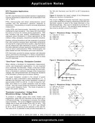
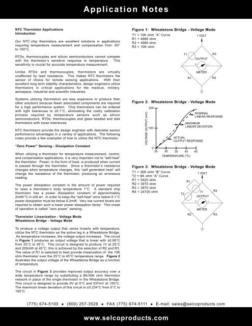
Figure 1: Wheatstone Bridge - Voltage Mode<br />
T1 = 10K ohm “A” Curve<br />
1 VOLT<br />
R1 = 4980 ohm<br />
R2 = 4980 ohm<br />
R3 = 10K ohm<br />
T1<br />
OUTPUT<br />
+ -<br />
R3<br />
Unlike RTDs and thermocouples, thermistors are virtually<br />
unaffected by lead resistance. This makes NTC thermistors the<br />
sensor of choice for remote sensing applications. With their<br />
excellent long term stability characteristics, design engineers utilize<br />
thermistors in critical applications for the medical, military,<br />
aerospace, industrial and scientific industries.<br />
R1<br />
METER<br />
R2<br />
Systems utilizing thermistors are less expensive to produce than<br />
other solutions because fewer associated components are required<br />
for a high performance system. Chip thermistors can be ordered<br />
with tight tolerances to ±0.1°C, eliminating the costly calibration<br />
process required by temperature sensors such as silicon<br />
semiconductors, RTDs, thermocouples and glass beaded and disk<br />
thermistors with loose tolerances.<br />
NTC thermistors provide the design engineer with desirable sensor<br />
performance advantages in a variety of applications. The following<br />
notes provide a few examples of how to utilize the NTC thermistor.<br />
“Zero Power” Sensing - Dissipation Constant<br />
When utilizing a thermistor for temperature measurement, control,<br />
and compensation applications, it is very important not to “self-heat”<br />
the thermistor. Power, in the form of heat, is produced when current<br />
is passed through the thermistor. Since a thermistor’s resistance<br />
changes when temperature changes, this “self generated heat” will<br />
change the resistance of the thermistor, producing an erroneous<br />
reading.<br />
The power dissipation constant is the amount of power required<br />
to raise a thermistor’s body temperature 1°C. A standard chip<br />
thermistor has a power dissipation constant of approximately<br />
2mW/°C in still air. In order to keep the “self-heat” error below 0.1°C<br />
power dissipation must be below 0.2mW. Very low current levels are<br />
required to obtain such a lower power dissipation factor. This mode<br />
of operation is called “zero power” sensing.<br />
Thermistor Linearization - Voltage Mode<br />
Wheatstone Bridge - Voltage Mode<br />
Figure 2: Wheatstone Bridge - Voltage Mode<br />
VOLTAGE OUTPUT (mV)<br />
200<br />
100<br />
0<br />
25<br />
ACTUAL<br />
OUTPUT RESPONSE<br />
30 35 40 45<br />
O<br />
TEMPERATURE ( C)<br />
NOMINAL<br />
LINEAR RESPONSE<br />
MAXIMUM<br />
LINEAR DEVIATION<br />
Figure 3: Wheatstone Bridge - Voltage Mode<br />
T1 = 30K ohm “B” Curve<br />
T2 = 6K ohm “A” Curve<br />
R1 = 5420 ohm<br />
R2 = 3970 ohm<br />
R3 = 3970 ohm<br />
R4 = 24720 ohm<br />
T2<br />
R1<br />
R2<br />
1 VOLT<br />
T1<br />
OUTPUT<br />
+ -<br />
METER<br />
R4<br />
R3<br />
To produce a voltage output that varies linearly with temperature,<br />
utilize the NTC thermistor as the active leg in a Wheatstone Bridge.<br />
As temperature increases, the voltage output increases. The circuit<br />
in Figure 1 produces an output voltage that is linear with ±0.06°C<br />
from 25°C to 45°C. This circuit is designed to produce 1V at 25°C<br />
and 200mW at 45°C; this is achieved by the selection of R2 and R3.<br />
The value of R1 is selected to best provide linearization of the 10K<br />
ohm thermistor over the 25°C to 45°C temperature range. Figure 2<br />
illustrates the output voltage of the Wheatstone Bridge as a function<br />
of temperature.<br />
The circuit in Figure 3 provides improved output accuracy over a<br />
wide temperature range by substituting a 6K/30K ohm thermistor<br />
network in place of the single thermistor in the Wheatstone Bridge.<br />
This circuit is designed to provide 0V at 0°C and 537mV at 100°C.<br />
The maximum linear deviation of this circuit is ±0.234°C from 0°C to<br />
100°C.<br />
(775) 674-5100 (800) 257-3526 FAX (775) 674-5111 E-mail: sales@selcoproducts.com<br />
www.selcoproducts.com
<strong>Application</strong> <strong>Notes</strong><br />
Thermistor Linearization<br />
Operational Amplifier - Resistance Mode<br />
A linear voltage output that varies with temperature can also be<br />
produced by utilizing an operational amplifier and a linearized<br />
thermistor network as illustrated in Figure 4. The voltage output<br />
decreases linearly as temperature increases. This circuit may be<br />
calibrated by adjusting R3 for an output voltage of 200mW at 25°C<br />
and 0V at 45°C.<br />
Figure 4: Linearization - Resistance Mode<br />
T1 = 10K ohm “A” Curve<br />
R1<br />
R1 = 4980 ohm<br />
R2 = 5K ohm<br />
T1<br />
R3 = 10K ohm potentiometer<br />
R3<br />
R2<br />
-<br />
+<br />
Temperature Measurement and Control<br />
Digital Thermometer<br />
The most common application for the NTC thermistor is temperature<br />
measurement. Accurate temperature measurement can easily be<br />
accomplished by interfacing a Wheatstone Bridge, 6K/30K ohm<br />
thermistor network and a digital voltmeter integrated circuit as<br />
illustrated in Figure 5. The IC consist of an analog to digital<br />
converter with built-in 3-1/2 digit LCD driver providing resolution of<br />
0.1°C. Using the 6K/30K ohm thermistor network makes it possible<br />
to achieve an overall system accuracy of ±0.4°C from 0°C to 100°C.<br />
This digital thermometer can easily be interfaced with additional<br />
circuitry to provide a temperature control circuit with a digital display.<br />
Micro Controller System<br />
The advent of low cost micro controllers used with precision<br />
interchangeable NTC thermistors, provides the design engineer with<br />
unlimited design possibilities for temperature measurement and<br />
control systems. These systems are relatively inexpensive to<br />
produce yet offer very high temperature accuracy and various<br />
software controlled outputs.<br />
For example, a micro controller system utilizing remote thermistor<br />
sensors can monitor and control the temperature in several<br />
locations in an office building. For this case, the micro controller is<br />
comprised of a built-in microprocessor, analog to digital converter,<br />
RAM and several digital inputs/outputs. The complete system<br />
Figure 6 utilizes the micro controller, multiplexer, EPROM, digital<br />
display, keypad and display driver.<br />
The micro controller is programmed in assembler language. The<br />
temperature measurement is calculated within the micro controller<br />
using the resistance versus temperature algorithm and the a, b<br />
and c, constants for the specific thermistor resistance and curve<br />
material. Refer to the Steinhart Equation on page 5. An alternative<br />
method to convert the thermistor resistance to temperature is to<br />
program a “look-up” table in EPROM. After programming, the micro<br />
controller tells the multiplexer to send back temperature data from<br />
a particular zone (room in the office building) and converts the<br />
resistance of the thermistor into a temperature reading.<br />
Figure 5: Digital Thermometer<br />
R7 = 1.50K ohm<br />
R8 = 100K ohm<br />
R9 = 470K ohm<br />
R10 = 15K ohm<br />
C1 = 100 pF<br />
C2 = 0.22<br />
C4 = 0.1<br />
T1<br />
T2<br />
R2<br />
R2<br />
R4<br />
R5<br />
R6<br />
R7<br />
R10<br />
R3<br />
C4<br />
R8<br />
C1<br />
40 39 38<br />
36<br />
34<br />
33<br />
Figure 6: Micro Controller System<br />
THERMISTOR<br />
ZONE 1<br />
THERMISTOR<br />
ZONE 2<br />
THERMISTOR<br />
ZONE 3<br />
THERMISTOR<br />
ZONE 4<br />
THERMISTOR<br />
ZONE 5<br />
THERMISTOR<br />
ZONE 6<br />
MULTI-<br />
PLEXER<br />
31<br />
30<br />
36<br />
A/D<br />
INPUT<br />
KEYPAD<br />
1<br />
R9<br />
C2<br />
32 26<br />
DISPLAY<br />
70 O<br />
C<br />
DISPLAY DRIVER<br />
MICRO<br />
CONTROLLER<br />
EPROM<br />
C3<br />
29 28 27<br />
2<br />
3<br />
20<br />
22<br />
25<br />
21<br />
+9V<br />
S1<br />
HEAT/AC<br />
ZONE1<br />
HEAT/AC<br />
ZONE 2<br />
HEAT/AC<br />
ZONE 3<br />
HEAT/AC<br />
ZONE 4<br />
HEAT/AC<br />
ZONE 5<br />
HEAT/AC<br />
ZONE 6<br />
TO<br />
LCD<br />
The micro controller can then turn on or off the heating or air<br />
conditioning systems in a specific zone.<br />
The thermistor/micro controller system can be used for security,<br />
temperature control, monitoring activities and many other<br />
applications. The possibilities are endless.<br />
(775) 674-5100 (800) 257-3526 FAX (775) 674-5111 E-mail: sales@selcoproducts.com<br />
www.selcoproducts.com
<strong>Application</strong> <strong>Notes</strong><br />
Temperature Compensation<br />
NTC thermistors can be used to compensate for the temperature<br />
coefficient response of various components such as crystal<br />
oscillators, mechanical meters and infrared LEDs. A thermistor/<br />
resistor network Figure 7 is placed in series with a PTC component<br />
requiring compensation. The resistor values are selected to provide<br />
the proper NTC slope to offset the PTC component. The net effect<br />
is a constant circuit response that is independent of temperature.<br />
“Self-Heat” Sensing <strong>Application</strong>s<br />
Figure 7: Temperature Compensation<br />
T1<br />
R1<br />
R2<br />
COPPER COIL<br />
METER<br />
RESPONSE<br />
METER CIRCUIT<br />
RESPONSE<br />
TEMPERATURE<br />
PTC COMPONENT<br />
RESPONSE<br />
NTC THERMISTOR<br />
NETWORK<br />
To “self-heat” a thermistor, it must be subjected to power levels that<br />
raise the thermistor’s body temperature above the environmental<br />
surroundings. Self-heat applications include the sensing of liquid,<br />
air level, and flow rates. This application is dependent on the fact<br />
that the environment surrounding a thermistor directly affects the<br />
amount of power the thermistor can dissipate. For example,<br />
submerged in liquid, a thermistor can typically dissipate 500% to<br />
600% more power than it can air.<br />
Therefore, a thermistor being “self-heated” in air is able to dissipate<br />
much more power when transferred to a fluid environment. This<br />
increase in power dissipation generates a significant increase in<br />
resistance. It is this change in resistance, which makes it possible<br />
to sense the fluid level.<br />
A simple liquid level control system can be designed by putting a<br />
thermistor in series with a coil Figure 8, which operates a valve that<br />
releases the liquid in the tank. The thermistor is placed in the tank<br />
and operated in a “self-heat” mode.<br />
In air, the thermistor’s resistance is low and allows enough current<br />
flow to energize the relay coil and keep the relay contact closed.<br />
When the fluid level in the tank surrounds the thermistor, its<br />
resistance increases and de-energizes the relay, which opens a<br />
valve and releases the fluid. As the fluid is released from the tank,<br />
the thermistor’s resistance decreases and the relay coil energizes<br />
and closes the valve.<br />
Fuel injection in automobiles utilize the thermistor in the “self-heat”<br />
mode in order to properly control the air/fuel mixture. Forced air<br />
heaters may use the NTC thermistor in the “self-heat” mode in order<br />
to maintain proper air flow characteristics. This technology is<br />
utilized to monitor the flow rate and level of air and fluids in a<br />
variety of applications.<br />
Figure 8: Self-Heat <strong>Application</strong>s<br />
T1<br />
VALVE<br />
RELAY<br />
COIL<br />
01/10-mb<br />
(775) 674-5100 (800) 257-3526 FAX (775) 674-5111 E-mail: sales@selcoproducts.com<br />
www.selcoproducts.com