realtek single chip 16-port 10/100 ethernet ... - Cornelius-Consult
realtek single chip 16-port 10/100 ethernet ... - Cornelius-Consult
realtek single chip 16-port 10/100 ethernet ... - Cornelius-Consult

You also want an ePaper? Increase the reach of your titles
YUMPU automatically turns print PDFs into web optimized ePapers that Google loves.
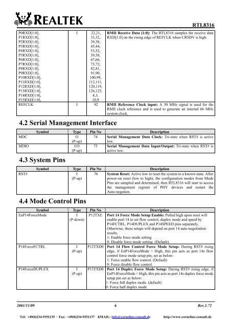
P0RXD[1:0],<br />
P1RXD[1:0],<br />
P2RXD[1:0],<br />
P3RXD[1:0],<br />
P4RXD[1:0],<br />
P5RXD[1:0],<br />
P6RXD[1:0],<br />
P7RXD[1:0],<br />
P8RXD[1:0],<br />
P9RXD[1:0],<br />
P<strong>10</strong>RXD[1:0],<br />
P11RXD[1:0],<br />
P12RXD[1:0],<br />
P13RXD[1:0],<br />
P14RXD[1:0],<br />
P15RXD[1:0],<br />
I 22,21,<br />
33,32,<br />
39,38,<br />
45,44,<br />
53,52,<br />
59,58,<br />
67,66,<br />
73,72,<br />
82,81,<br />
91,90,<br />
<strong>10</strong>0,99,<br />
112,111,<br />
120,119,<br />
126,125,<br />
4,3,<br />
<strong>10</strong>,9<br />
RTL83<strong>16</strong><br />
RMII Receive Data [1:0]: The RTL83<strong>16</strong> samples the receive data<br />
RXD[1:0] on the rising edge of REFCLK when CRSDV is high.<br />
REFCLK I 92 RMII Reference Clock input: A 50 MHz signal is used for the<br />
RMII clock reference and is used to generate an internal 66 MHz<br />
system clock.<br />
4.2 Serial Management Interface<br />
MDC<br />
MDIO<br />
Symbol Type Pin No Description<br />
O 74 Serial Management Data Clock: Tri-state when RST# is active<br />
(P-up)<br />
low.<br />
I/O 75 Serial Management Data Input/Output: Tri-state when RST# is<br />
(P-up)<br />
active low.<br />
4.3 System Pins<br />
RST#<br />
Symbol Type Pin No Description<br />
I 76 System Reset: Active low to reset the system to a known state. After<br />
(P-up)<br />
power-on reset (low to high), the configuration modes from Mode<br />
Pins are sampled and determined, then RTL83<strong>16</strong> will start to access<br />
the management register of PHY devices and restart the<br />
Auto-negation.<br />
4.4 Mode Control Pins<br />
Symbol Type Pin No Description<br />
EnP14ForceMode<br />
I<br />
(P-down)<br />
P12TXE Port 14 Force Mode Setup Enable: Pulled high upon reset will<br />
enable <strong>port</strong> 14 to set flow control, duplex mode and speed by<br />
P14FCTRL, P14DUPLEX and P14SPEED pins separately.<br />
Otherwise, these setups will depend on <strong>port</strong> 14 auto-negotiation<br />
results.<br />
1: Enable force mode setting<br />
P14ForceFCTRL<br />
P14ForceDUPLEX<br />
I<br />
(P-up)<br />
I<br />
(P-up)<br />
0: Disable force mode setting (Default)<br />
P12TXD0 Port 14 Flow Control Force Mode Setup: During RST# rising<br />
edge, if EnP14ForceMode = High, this pin acts as <strong>port</strong> 14s flow<br />
control force mode setup pin, set as below:<br />
1: Force enable flow control. (Default)<br />
0: Force disable flow control.<br />
P13TXD0 Port 14 Duplex Force Mode Setup: During RST# rising edge, if<br />
EnP14ForceMode = High, this pin acts as <strong>port</strong> 14s duplex force mode<br />
setup pin set as below:<br />
1: Force full duplex mode. (default)<br />
0: Force half duplex mode<br />
2001/11/09 6<br />
Rev.1.72<br />
Tel: +49(0)234-9351135 · Fax: +49(0)234-9351137 E-MAIL: info@cornelius-consult.de http://www.cornelius-consult.de