realtek single chip 16-port 10/100 ethernet ... - Cornelius-Consult
realtek single chip 16-port 10/100 ethernet ... - Cornelius-Consult
realtek single chip 16-port 10/100 ethernet ... - Cornelius-Consult

You also want an ePaper? Increase the reach of your titles
YUMPU automatically turns print PDFs into web optimized ePapers that Google loves.
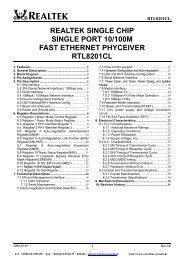
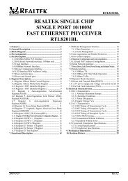
RTL83<strong>16</strong><br />
REALTEK SINGLE CHIP<br />
<strong>16</strong>-PORT <strong>10</strong>/<strong>10</strong>0 ETHERNET<br />
SWITCH CONTROLLER<br />
WITH EMBEDDED MEMORY<br />
RTL83<strong>16</strong><br />
1. Features........................................................................ 2<br />
2. General Description .................................................... 2<br />
3. Pin Assignments .......................................................... 4<br />
4. Pin Description ............................................................ 5<br />
4.1 RMII Interface (Port #0 ~ Port #15)....................... 5<br />
4.2 Serial Management Interface.................................. 6<br />
4.3 System Pins ............................................................ 6<br />
4.4 Mode Control Pins ................................................. 6<br />
4.5 LED Pins................................................................ 9<br />
4.6 Power / Ground Pins .............................................. 9<br />
4.7 Test Pins ................................................................. 9<br />
5. Block Diagram........................................................... <strong>10</strong><br />
6. Functional Description ..............................................11<br />
6.1 Reset..................................................................... 11<br />
6.2 RMII interface...................................................... 11<br />
6.3 Serial Management Interface MDC/MDIO.......... 11<br />
6.4 Address Search and Learning............................... 12<br />
6.5 Address Aging...................................................... 12<br />
6.6 Illegal Frames....................................................... 12<br />
6.7 802.1D Reserved Group Addresses Filtering....... 12<br />
6.8 Back off Algorithm .............................................. 12<br />
6.9 Inter-Frame Gap................................................... 12<br />
6.<strong>10</strong> Buffer Management ........................................... 13<br />
6.11 Buffer Manager .................................................. 13<br />
6.12 Data Reception................................................... 13<br />
6.13 Data Forwarding ................................................ 13<br />
6.14 Flow Control ...................................................... 14<br />
6.15 Broadcast Storm Filtering Control ..................... 14<br />
6.<strong>16</strong> Head-Of-Line Blocking Prevention ................... 14<br />
6.17 Port Trunking and Load Balance........................ 14<br />
6.18 Force Mode Setting of Port ability..................... 15<br />
6.19 Port Based HOME VLAN Function .................. 15<br />
6.20 QoS Function ..................................................... <strong>16</strong><br />
7. Electrical Characteristics ......................................... 17<br />
7.1 Temperature Limit Ratings: ................................. 17<br />
7.2 DC Characteristics ............................................... 17<br />
7.3 AC Characteristics ............................................... 17<br />
7.3.1 Reset and Clock Timing ............................... 17<br />
7.3.2 RMII Timing................................................. 18<br />
7.3.3 PHY Management (SMI) Timing ................. 19<br />
8. Mechanical Information........................................... 20<br />
9. Revision History........................................................ 21<br />
2001/11/09 1<br />
Rev.1.72<br />
Tel: +49(0)234-9351135 · Fax: +49(0)234-9351137 E-MAIL: info@cornelius-consult.de http://www.cornelius-consult.de
RTL83<strong>16</strong><br />
The Realtek RTL83<strong>16</strong> is a highly cost-effective <strong>16</strong>-<strong>port</strong> <strong>10</strong>/<strong>10</strong>0M Fast Ethernet switch controller which integrates a 4M-bit DRAM<br />
packet buffer, an 8K-entry look up table and a 128-entry CAM. Packaged in a 128-pin PQFP, the new <strong>chip</strong> features ultra-low power<br />
consumption as well as <strong>port</strong>-based Home VLAN, trunking, and 2-level QoS functions. With its high integration, enhanced features<br />
and micro-size, the RTL83<strong>16</strong> provides an economic and optimal solution for design of stand-alone switches. The RTL83<strong>16</strong> sup<strong>port</strong>s<br />
a Reduced MII (RMII) interface and requires only one 50MHz oscillator, saving BOM cost.<br />
1. Features<br />
• Sup<strong>port</strong>s up to <strong>16</strong> <strong>10</strong>/<strong>10</strong>0Mbps Full/Half<br />
duplex Ethernet <strong>port</strong>s with RMII interface<br />
• All <strong>port</strong>s sup<strong>port</strong> Speed, Duplex and<br />
Flow-control auto-negotiation<br />
• Two <strong>port</strong>s sup<strong>port</strong> Speed, Duplex and<br />
Flow-control by force-mode setting for fiber<br />
applications<br />
• Provides non-blocking and<br />
non-head-of-line-blocking forwarding<br />
• 4M bit DRAM built in as packet storage buffer<br />
uses page-based buffer management to<br />
efficiently utilize the internal packet buffer<br />
• Embedded 8K entry look-up table with direct<br />
mapping and 128 entries of CAM to eliminate<br />
hash collision problems<br />
• Only one 50MHz OSC input for both system<br />
clock and RMII reference clock<br />
• Sup<strong>port</strong>s tri-state design on MDC and MDIO<br />
during reset period<br />
• Flow control fully sup<strong>port</strong>ed:<br />
• Half-duplex: Back pressure<br />
• Full-duplex: IEEE 802.3x<br />
• Broadcast storm filtering control<br />
• Aging function sup<strong>port</strong>ed<br />
• Sup<strong>port</strong>s Store-and-forward operation<br />
• Port Trunking sup<strong>port</strong>ed. Four trunk groups<br />
are provided, each consisting of 4 physical<br />
<strong>port</strong>s. Trunk load balance is controlled by<br />
DA/SA hash algorithm. Trunk Port LEDs<br />
sup<strong>port</strong>ed.<br />
• Port based HOME VLAN function<br />
• Sup<strong>port</strong>s QoS function on each <strong>port</strong><br />
• QoS based on: (1) Port-based (2)VLAN<br />
tag (3) TCP/IP header's TOS/DS<br />
• Sup<strong>port</strong>s two level priority queues<br />
• Weighted round robin service<br />
• 128-pin PQFP, 3.3V <strong>single</strong> power technology<br />
2. General Description<br />
The RTL83<strong>16</strong> provides <strong>16</strong> <strong>10</strong>/<strong>10</strong>0 Mbps RMII Ethernet <strong>port</strong>s. Each <strong>port</strong> can operate in a <strong>10</strong> Mbps or <strong>10</strong>0 Mbps data rate, and<br />
in full or half duplex mode. Speed, duplex, link status and flow control can be acquired by periodically polling the status of the<br />
PHY devices via MDIO.<br />
Two <strong>port</strong>s can sup<strong>port</strong> Speed, Duplex and Flow-control abilities through force setting mode for fiber applications. The address<br />
look-up table consists of 8K entries of hash table and a 128 entries of CAM. The RTL83<strong>16</strong> uses 13 bit MAC address direct<br />
mapping method to search the destination MAC address and record source MAC address from and to the hash table.<br />
2001/11/09 2<br />
Rev.1.72<br />
Tel: +49(0)234-9351135 · Fax: +49(0)234-9351137 E-MAIL: info@cornelius-consult.de http://www.cornelius-consult.de
RTL83<strong>16</strong><br />
The RTL83<strong>16</strong> sup<strong>port</strong>s IEEE 802.3x full duplex flow control and half duplex back pressure control. The ability of IEEE<br />
802.3x flow control is auto-negotiated by writing the flow control ability via MDIO. For half duplex, the RTL83<strong>16</strong> adopts a<br />
special back pressure design to allow forwarding of one packet successfully after 48 force collisions. This back pressure<br />
algorithm can prevent the connected repeater from being partitioned due to excessive collisions. The full/half duplex flow<br />
control ability can be enabled or disabled via a hardware strap upon reset.<br />
The RTL83<strong>16</strong> provides a Broadcast storm filtering function which is provided to compensate for unusual broadcast storm<br />
interference.<br />
The RTL83<strong>16</strong> <strong>port</strong> trunking function sup<strong>port</strong>s the ability to aggregate four <strong>10</strong>/<strong>10</strong>0 <strong>port</strong>s into a <strong>single</strong> logical link to increase the<br />
bandwidth between the RTL83<strong>16</strong> and another device (switch or server) with trunking function enabled. Four Trunk Groups are<br />
sup<strong>port</strong>ed. The trunk load balance is controlled by the DA/SA hash algorithm. The load balancing algorithm will make sure<br />
that frame distribution does not become mis-ordered , and that there is no frame duplication in the <strong>port</strong> trunk.<br />
The RTL83<strong>16</strong> sup<strong>port</strong>s 3 types of QoS functions to improve multi-medium or real-time networking applications. They are<br />
based on: (1) Port based priority (2) 802.1p/Q VLAN priority tag (3) TCP/IP's TOS/DS (DiffServ) field. The QoS function can<br />
be easily enabled or disabled and configured by hardware pins without any EEPROM or CPU configuration required.<br />
There are two output queues on each output <strong>port</strong> when QoS is enabled: one is for high priority frames, the other is for low<br />
priority frames. The RTL83<strong>16</strong> sup<strong>port</strong>s an intelligent adaptive flow control for high priority frames in order to avoid the flow<br />
control function, which can affect the quality of high priority frames such as real-time multi-media application traffic. By<br />
setting EnFCAutoOff high upon reset, the RTL83<strong>16</strong> will automatically turn off the 802.3x flow control and back pressure flow<br />
control for 1~2 sec whenever the <strong>port</strong> receives high priority frames. Flow control will be re-enabled when no high priority<br />
frames are received during this 1~2 sec duration.<br />
All system configuration and control hardware pins have a default value, implemented through internal pull-high/low resisters.<br />
The RTL83<strong>16</strong> sup<strong>port</strong>s a <strong>port</strong> based HOME Virtual Local Area Network (VLAN) function for network topology security<br />
configuration. When the <strong>port</strong> based security function is enabled, the <strong>16</strong> <strong>port</strong>s of the RTL83<strong>16</strong> can be configured as 14<br />
individual VLANs that share the same two overlapping <strong>port</strong>s. Or, the <strong>16</strong> <strong>port</strong>s can be configured as 15 individual VLANs that<br />
share the same one overlapping <strong>port</strong>. This 14 VLANs or 15 VLANs topology is useful to allow home networks to share a<br />
common server or router, but be configured as different VLANs for security reasons.<br />
The RTL83<strong>16</strong> sup<strong>port</strong>s non-blocking 148800 packets/second wire speed forwarding rate and includes a special design to<br />
resolve head-of-line-blocking problems. Finally, only one 50MHz OSC is needed for system design.<br />
50MHz<br />
OSC<br />
Realtek<br />
RTL83<strong>16</strong><br />
Oct-PHY or<br />
2 Quad-PHY<br />
Oct-PHY or<br />
2 Quad-PHY<br />
<strong>10</strong>/<strong>10</strong>0 Mbps x<strong>16</strong><br />
Example of a <strong>16</strong>-<strong>port</strong> switch system<br />
2001/11/09 3<br />
Rev.1.72<br />
Tel: +49(0)234-9351135 · Fax: +49(0)234-9351137 E-MAIL: info@cornelius-consult.de http://www.cornelius-consult.de
RTL83<strong>16</strong><br />
3. Pin Assignments<br />
TRUNKLED1#<br />
TRUNKLED0#<br />
P<strong>10</strong>RXD1<br />
P<strong>10</strong>RXD0<br />
P<strong>10</strong>CRSDV<br />
P<strong>10</strong>TXD1<br />
P<strong>10</strong>TXD0<br />
P<strong>10</strong>TXE/ EnBKPS<br />
GND<br />
VCC<br />
REFCLK<br />
P9RXD1<br />
P9RXD0<br />
P9CRSDV<br />
P9TXD1<br />
P9TXD0/ FDFCTRL<br />
P9TXE/ EnBRDCTRL<br />
NC<br />
VCC<br />
GND<br />
P8RXD1<br />
P8RXD0<br />
P8CRSDV<br />
P8TXD1<br />
P8TXD0/ CtrlFrameFilter<br />
P8TXE<br />
RESET#<br />
MDIO<br />
MDC<br />
P7RXD1<br />
P7RXD0<br />
P7CRSDV<br />
P7TXD1<br />
P7TXD0/ QWeight[1]<br />
P7TXE/ QWeight[0]<br />
P6RXD1<br />
P6RXD0<br />
P6CRSDV<br />
TRUNKLED2# <strong>10</strong>3<br />
TRUNKLED3# <strong>10</strong>4<br />
VCC <strong>10</strong>5<br />
GND <strong>10</strong>6<br />
P11TXE/ EnValnType <strong>10</strong>8<br />
P11TXD0 <strong>10</strong>8<br />
P11TXD1 <strong>10</strong>9<br />
P11CRSDV 1<strong>10</strong><br />
P11RXD0 111<br />
P11RXD1 112<br />
VCC 113<br />
GND 114<br />
P12TXE/ EnP14ForceMode 115<br />
P12TXD0/ P14ForceFCTL 1<strong>16</strong><br />
P12TXD1 117<br />
P12CRSDV 118<br />
P12RXD0 119<br />
P12RXD1 120<br />
P13TXE/ P14ForceSPD 121<br />
P13TXD0/ P14ForceDUPX 122<br />
P13TXD1 123<br />
P13CRSDV 124<br />
P13RXD0 125<br />
P13RXD1 126<br />
P14TXE/ EnP15ForceMode 127<br />
P14TXD0/ P15ForceFCTL 128<br />
<strong>10</strong>2<br />
<strong>10</strong>1<br />
<strong>10</strong>0<br />
99<br />
98<br />
97<br />
96<br />
95<br />
94<br />
93<br />
92<br />
91<br />
90<br />
89<br />
88<br />
87<br />
86<br />
85<br />
84<br />
83<br />
82<br />
81<br />
80<br />
79<br />
78<br />
77<br />
76<br />
75<br />
74<br />
73<br />
72<br />
71<br />
70<br />
69<br />
68<br />
67<br />
66<br />
65<br />
RTL83<strong>16</strong><br />
64<br />
63<br />
62<br />
61<br />
60<br />
59<br />
58<br />
57<br />
56<br />
55<br />
54<br />
53<br />
52<br />
51<br />
50<br />
49<br />
48<br />
47<br />
46<br />
45<br />
44<br />
43<br />
42<br />
41<br />
40<br />
39<br />
P6TXD1<br />
P6TXD0/ EnPortPri[1]<br />
P6TXE/ EnPortPri[0]<br />
GND<br />
VCC<br />
P5RXD1<br />
P5RXD0<br />
P5CRSDV<br />
P5TXD1<br />
P5TXD0/ En8021pPri<br />
P5TXE/ EnDSPri<br />
P4RXD1<br />
P4RXD0<br />
P4CRSDV<br />
P4TXD1<br />
P4TXD0/ EnFCAutoOff<br />
P4TXE<br />
GND<br />
VCC<br />
P3RXD1<br />
P3RXD0<br />
P3CRSDV<br />
P3TXD1<br />
P3TXD0/ EnBKP28One<br />
P3TXE/ EnTrunk3<br />
P2RXD1<br />
P14TXD1 1<br />
P14CRSDV 2<br />
P14RXD0 3<br />
P14RXD1 4<br />
P15TXE/ P15ForceSPD 5<br />
P15TXD0/ P15ForceDUPX 6<br />
P15TXD1 7<br />
P15CRSDV 8<br />
P15RXD0 9<br />
P15RXD1 <strong>10</strong><br />
GND 11<br />
VCC 12<br />
NC 13<br />
NC 14<br />
GND 15<br />
VCC <strong>16</strong><br />
P0TXE 17<br />
P0TXD0/ EnVLAN 18<br />
P0TXD1 19<br />
P0CRSDV 20<br />
P0RXD0 21<br />
P0RXD1 22<br />
NC 23<br />
VCC 24<br />
GND 25<br />
P1TXE 26<br />
GND 27<br />
VCC 28<br />
P1TXD0/ EnTrunk0 29<br />
P1TXD1 30<br />
P1CRSDV 31<br />
P1RXD0 32<br />
P1RXD1 33<br />
P2TXE/ EnTrunk1 34<br />
P2TXD0/ EnTrunk2 35<br />
P2TXD1 36<br />
P2CRSDV 37<br />
P2RXD0 38<br />
2001/11/09 4<br />
Rev.1.72<br />
Tel: +49(0)234-9351135 · Fax: +49(0)234-9351137 E-MAIL: info@cornelius-consult.de http://www.cornelius-consult.de
RTL83<strong>16</strong><br />
4. Pin Description<br />
4.1 RMII Interface (Port #0 ~ Port #15)<br />
P0TXE,<br />
P1TXE,<br />
P2TXE,<br />
P3TXE,<br />
P4TXE,<br />
P5TXE,<br />
P6TXE,<br />
P7TXE,<br />
P8TXE,<br />
P9TXE,<br />
P<strong>10</strong>TXE,<br />
P11TXE,<br />
P12TXE,<br />
P13TXE,<br />
P14TXE,<br />
P15TXE,<br />
P0TXD[1:0],<br />
P1TXD[1:0],<br />
P2TXD[1:0],<br />
P3TXD[1:0],<br />
P4TXD[1:0],<br />
P5TXD[1:0],<br />
P6TXD[1:0],<br />
P7TXD[1:0],<br />
P8TXD[1:0],<br />
P9TXD[1:0],<br />
P<strong>10</strong>TXD[1:0],<br />
P11TXD[1:0],<br />
P12TXD[1:0],<br />
P13TXD[1:0],<br />
P14TXD[1:0],<br />
P15TXD[1:0],<br />
P0CRSDV,<br />
P1CRSDV,<br />
P2CRSDV,<br />
P3CRSDV,<br />
P4CRSDV,<br />
P5CRSDV,<br />
P6CRSDV,<br />
P7CRSDV,<br />
P8CRSDV,<br />
P9CRSDV,<br />
P<strong>10</strong>CRSDV,<br />
P11CRSDV,<br />
P12CRSDV,<br />
P13CRSDV,<br />
P14CRSDV,<br />
P15CRSDV,<br />
Symbol Type Pin No Description<br />
O 17,<br />
26,<br />
34,<br />
40,<br />
48,<br />
54,<br />
62,<br />
77,<br />
68,<br />
86,<br />
95,<br />
<strong>10</strong>7,<br />
115,<br />
121,<br />
127,<br />
5<br />
O 19,18,<br />
30,29,<br />
36,35,<br />
42,41,<br />
50,49,<br />
56,55,<br />
64,63,<br />
70,69,<br />
79,78,<br />
88,87,<br />
97,96,<br />
<strong>10</strong>9,<strong>10</strong>8,<br />
117,1<strong>16</strong>,<br />
123,122,<br />
1,128,<br />
7, 6<br />
I 20,<br />
31,<br />
37,<br />
43,<br />
51,<br />
57,<br />
65,<br />
71,<br />
80,<br />
89,<br />
98,<br />
1<strong>10</strong>,<br />
118,<br />
124,<br />
2,<br />
8<br />
RMII Transmit Enable: The RTL83<strong>16</strong> asserts high to indicate that<br />
valid data for transmission is presented on the TXD[1:0]. It is<br />
synchronous with REFCLK.<br />
RMII Transmit Data [1:0]: The RTL83<strong>16</strong> transmit data TXD[1:0]<br />
is clocked out by the rising edge of REFCLK.<br />
RMII CRSDV signals: CRSDV from PHY device is asserted high<br />
when media is non-idle.<br />
2001/11/09 5<br />
Rev.1.72<br />
Tel: +49(0)234-9351135 · Fax: +49(0)234-9351137 E-MAIL: info@cornelius-consult.de http://www.cornelius-consult.de
P0RXD[1:0],<br />
P1RXD[1:0],<br />
P2RXD[1:0],<br />
P3RXD[1:0],<br />
P4RXD[1:0],<br />
P5RXD[1:0],<br />
P6RXD[1:0],<br />
P7RXD[1:0],<br />
P8RXD[1:0],<br />
P9RXD[1:0],<br />
P<strong>10</strong>RXD[1:0],<br />
P11RXD[1:0],<br />
P12RXD[1:0],<br />
P13RXD[1:0],<br />
P14RXD[1:0],<br />
P15RXD[1:0],<br />
I 22,21,<br />
33,32,<br />
39,38,<br />
45,44,<br />
53,52,<br />
59,58,<br />
67,66,<br />
73,72,<br />
82,81,<br />
91,90,<br />
<strong>10</strong>0,99,<br />
112,111,<br />
120,119,<br />
126,125,<br />
4,3,<br />
<strong>10</strong>,9<br />
RTL83<strong>16</strong><br />
RMII Receive Data [1:0]: The RTL83<strong>16</strong> samples the receive data<br />
RXD[1:0] on the rising edge of REFCLK when CRSDV is high.<br />
REFCLK I 92 RMII Reference Clock input: A 50 MHz signal is used for the<br />
RMII clock reference and is used to generate an internal 66 MHz<br />
system clock.<br />
4.2 Serial Management Interface<br />
MDC<br />
MDIO<br />
Symbol Type Pin No Description<br />
O 74 Serial Management Data Clock: Tri-state when RST# is active<br />
(P-up)<br />
low.<br />
I/O 75 Serial Management Data Input/Output: Tri-state when RST# is<br />
(P-up)<br />
active low.<br />
4.3 System Pins<br />
RST#<br />
Symbol Type Pin No Description<br />
I 76 System Reset: Active low to reset the system to a known state. After<br />
(P-up)<br />
power-on reset (low to high), the configuration modes from Mode<br />
Pins are sampled and determined, then RTL83<strong>16</strong> will start to access<br />
the management register of PHY devices and restart the<br />
Auto-negation.<br />
4.4 Mode Control Pins<br />
Symbol Type Pin No Description<br />
EnP14ForceMode<br />
I<br />
(P-down)<br />
P12TXE Port 14 Force Mode Setup Enable: Pulled high upon reset will<br />
enable <strong>port</strong> 14 to set flow control, duplex mode and speed by<br />
P14FCTRL, P14DUPLEX and P14SPEED pins separately.<br />
Otherwise, these setups will depend on <strong>port</strong> 14 auto-negotiation<br />
results.<br />
1: Enable force mode setting<br />
P14ForceFCTRL<br />
P14ForceDUPLEX<br />
I<br />
(P-up)<br />
I<br />
(P-up)<br />
0: Disable force mode setting (Default)<br />
P12TXD0 Port 14 Flow Control Force Mode Setup: During RST# rising<br />
edge, if EnP14ForceMode = High, this pin acts as <strong>port</strong> 14s flow<br />
control force mode setup pin, set as below:<br />
1: Force enable flow control. (Default)<br />
0: Force disable flow control.<br />
P13TXD0 Port 14 Duplex Force Mode Setup: During RST# rising edge, if<br />
EnP14ForceMode = High, this pin acts as <strong>port</strong> 14s duplex force mode<br />
setup pin set as below:<br />
1: Force full duplex mode. (default)<br />
0: Force half duplex mode<br />
2001/11/09 6<br />
Rev.1.72<br />
Tel: +49(0)234-9351135 · Fax: +49(0)234-9351137 E-MAIL: info@cornelius-consult.de http://www.cornelius-consult.de
P14ForceSPEED<br />
EnP15ForceMode<br />
P15ForceFCTRL<br />
P15ForceDUPLEX<br />
P15ForceSPEED<br />
ENBRDCTRL<br />
EnCtrlFrameFilter<br />
EnBKPRS<br />
ENFDFCTRL<br />
ENTRUNK0<br />
ENTRUNK1<br />
ENTRUNK2<br />
ENTRUNK3<br />
I<br />
(P-up)<br />
I<br />
(P-down)<br />
I<br />
(P-up)<br />
I<br />
(P-up)<br />
I<br />
(P-up)<br />
I<br />
(P-down)<br />
I<br />
(P-down)<br />
I<br />
(P-up)<br />
I<br />
(P-up)<br />
I/O<br />
(P-down)<br />
I/O<br />
(P-down)<br />
I/O<br />
(P-down)<br />
I/O<br />
(P-down)<br />
RTL83<strong>16</strong><br />
P13TXE Port 14 Speed Force Mode Setup: During RST# rising edge, if<br />
EnP14ForceMode = High, this pin acts as <strong>port</strong> 14s speed force mode<br />
setup pin set as below:<br />
1: Force <strong>10</strong>0 Mbps speed. (default)<br />
0: Force <strong>10</strong> Mbps speed.<br />
P14TXE Port 15 Force Mode Setup Enable: Pulled high upon reset will<br />
enable <strong>port</strong> 15 to set flow control, duplex mode and speed by<br />
P15FCTRL, P15DUPLEX and P15SPEED pins separately. Otherwise,<br />
the setup will depends on <strong>port</strong> 15s auto-negotiation results.<br />
1: Enable force mode setting<br />
0: Disable force mode setting (default)<br />
P14TXD0 Port 15 Flow Control Force Mode Setup: During RST# rising<br />
edge, if EnP15ForceMode = High, this pin acts as <strong>port</strong> 15s flow<br />
control force mode setup pin set as below:<br />
1: Force enable flow control (default)<br />
0: Force disable flow control<br />
P15TXD0 Port 15 Duplex Force Mode Setup: During RST# rising edge, if<br />
EnP15ForceMode = High, this pin acts as <strong>port</strong> 15s duplex force mode<br />
setup pin set as below:<br />
1: Force full duplex mode (default)<br />
0: Force half duplex mode<br />
P15TXE Port 15 Speed Force Mode Setup: During RST# rising edge, if<br />
EnP15ForceMode = High, this pin acts as <strong>port</strong> 15s speed force mode<br />
setup pin set as below:<br />
1: Force <strong>10</strong>0 Mbps speed (default)<br />
0: Force <strong>10</strong> Mbps speed<br />
P9TXE Enable Broadcast Storm Filtering Control: Pulled high upon reset<br />
will enable the broadcast storm control function. Pulled low upon<br />
reset will disable the broadcast storm control function.<br />
P8TXD0 Enable 802.1D specified reserved group MAC addresses frame<br />
filtering: When network control frames are received with the destination<br />
MAC address as a group MAC address: (01-80-C2-00-00-03 ~<br />
01-80-C2-00-00-0F), the RTL83<strong>16</strong> will drop the frames if the<br />
EnCtrlFrameFilter is set. Otherswise , it will be flooded. The value of<br />
EnCtrlFrameFilter is trapped on the power on reset.<br />
1: Enable drop<br />
0: Disable drop (default)<br />
P<strong>10</strong>TXE Enable Back pressure flow control function<br />
During hardware reset, the pull-high/low value will control the Back<br />
pressure flow control function.<br />
1: Enable back pressure (default)<br />
P9TXD0<br />
P1TXD0<br />
P2TXE<br />
P2TXD0<br />
P3TXE<br />
0: Disable back pressure<br />
Enable Full Duplex 802.3x Flow Control: Pulled high upon reset<br />
will enable the full duplex IEEE802.3x flow control function. The<br />
flow control ability will be written to management register 4 of the<br />
PHY device once (and only once) after power-on reset, for<br />
advertising.<br />
Pulled low upon reset will disable the full duplex flow control<br />
function.<br />
Enable Port Trunk 0: Pulled high upon reset will enable <strong>port</strong> trunk<br />
0 which consists of <strong>port</strong>s 0,1,2,3.<br />
Enable Port Trunk 1: Pulled high upon reset will enable <strong>port</strong> trunk<br />
1 which consists of <strong>port</strong>s 4,5,6,7.<br />
Enable Port Trunk 2: Pulled high upon reset will enable <strong>port</strong> trunk<br />
2 which consists of <strong>port</strong>s 8,9,<strong>10</strong>,11.<br />
Enable Port Trunk 3: Pulled high upon reset will enable <strong>port</strong> trunk<br />
3 which consists of <strong>port</strong>s 12,13,14,15.<br />
2001/11/09 7<br />
Rev.1.72<br />
Tel: +49(0)234-9351135 · Fax: +49(0)234-9351137 E-MAIL: info@cornelius-consult.de http://www.cornelius-consult.de
ENVLAN<br />
VlanType<br />
EnPortPri[1:0]<br />
En8021pPri<br />
EnDSPri<br />
QWEIGHT[1:0]<br />
EnFCAutoOff<br />
I<br />
(P-down)<br />
I<br />
(P-down)<br />
I<br />
(P-down,<br />
P-down)<br />
I<br />
(P-down)<br />
I<br />
(P-down)<br />
I<br />
(P-up,<br />
P-up)<br />
I<br />
(P-down)<br />
RTL83<strong>16</strong><br />
P0TXD0 Enable Port Based VLAN configuration function: Latched during<br />
hardware reset. The VLAN topology is control by VlanType pin, but<br />
will be disabled if the trunking function is enabled.<br />
1: Enable the VLAN function on each <strong>port</strong>.<br />
0: Disable the VLAN function on each <strong>16</strong> <strong>port</strong>s. (default)<br />
P11TXE VLAN topology type selection: Used to select 14 VLANs or 15<br />
VLANs topology. During hardware reset, the pull-high/low value will<br />
control the HOME VLAN topology type :<br />
1: Select 15 VALNs (<strong>port</strong>#0~14) with 1 overlapping <strong>port</strong><br />
(<strong>port</strong> #15) topology.<br />
0: Select 14 VLANs (<strong>port</strong>#0~13) with 2 overlapping <strong>port</strong>s<br />
[P6TXD0,<br />
P6TXE]<br />
P5TXD0<br />
P5TXE<br />
[P7TXD0,<br />
P7TXE]<br />
P4TXD0<br />
(<strong>port</strong> #14,15) topology. (default)<br />
Enable Port based priority QoS function: Latched during<br />
hardware reset. Setting as follows:<br />
00: Disable <strong>port</strong> based priority. (default)<br />
01: Set <strong>port</strong>#0~1 as high priority <strong>port</strong>s. (2 <strong>port</strong>s)<br />
<strong>10</strong>: Set <strong>port</strong>#0~3 as high priority <strong>port</strong>s. (4 <strong>port</strong>s)<br />
11: Set <strong>port</strong>#0~7 as high priority <strong>port</strong>s. (8 <strong>port</strong>s)<br />
Enable 802.1p VLAN Tag priority based QoS function: Latched<br />
during hardware reset.<br />
1: Enabled<br />
0: Disabled (default)<br />
Enable TCP/IP TOS/DS (DiffServ) based QoS function: Latched<br />
during hardware reset.<br />
1: Enabled<br />
High Priority: if TOS/DS[0:5] =<br />
(EF) "<strong>10</strong>11<strong>10</strong>";<br />
(AF) "00<strong>10</strong><strong>10</strong>", "0<strong>10</strong>0<strong>10</strong>",<br />
"01<strong>10</strong><strong>10</strong>", "<strong>10</strong>00<strong>10</strong>";<br />
(Network Control) "11x000";<br />
Low Priority: if TOS/DS = other<br />
codepoint values.<br />
0: Disabled (default)<br />
(DS = Differentiated Service)<br />
Weighted round robin ration of priority queue: Latched during<br />
hardware reset.<br />
The frame service rate is<br />
High-pri queue: Low-pri queue<br />
11 = always high priority queue first (default)<br />
<strong>10</strong> = 8:1<br />
01 = 4:1<br />
00 = 2:1<br />
Enable Flow Control Ability Auto Turn Off: Latched during<br />
hardware reset. Enable Auto turn off low priority queue's flow<br />
control ability 1~2 seconds whenever the <strong>port</strong> received a high<br />
priority frame. The flow control ability will be re-enabled when no<br />
high priority frames are received for the 1~2 second period.<br />
1: Enabled<br />
0: Disabled<br />
2001/11/09 8<br />
Rev.1.72<br />
Tel: +49(0)234-9351135 · Fax: +49(0)234-9351137 E-MAIL: info@cornelius-consult.de http://www.cornelius-consult.de
RTL83<strong>16</strong><br />
4.5 LED Pins<br />
Symbol Type Pin No Description<br />
TRUNKLED0#<br />
I/O<br />
(P-down)<br />
<strong>10</strong>1 Port Trunk 0 Status LED: After reset, this pin acts as the <strong>port</strong> trunk<br />
0 status LED. The LED will be active low when <strong>port</strong> trunk 0 is<br />
enabled. It will blink for 250ms ON and 250ms OFF when any<br />
physical <strong>port</strong> link failures occur within the enabled <strong>port</strong> trunk. It is<br />
TRUNKLED1#<br />
TRUNKLED2#<br />
TRUNKLED3#<br />
I/O<br />
(P-down)<br />
I/O<br />
(P-down)<br />
I/O<br />
(P-down)<br />
4.6 Power / Ground Pins<br />
dark when <strong>port</strong> trunk 0 is disabled.<br />
<strong>10</strong>2 Port Trunk 1 Status LED: After reset, this pin acts as the <strong>port</strong> trunk<br />
1 status LED. The LED will be active low when <strong>port</strong> trunk 1 is<br />
enabled. It will blink for 250ms ON and 250ms OFF when any<br />
physical <strong>port</strong> link failures occur within the enabled <strong>port</strong> trunk. It is<br />
dark when <strong>port</strong> trunk 1 is disabled.<br />
<strong>10</strong>3 Port Trunk 2 Status LED: After reset, this pin acts as the <strong>port</strong> trunk<br />
2 status LED. The LED will be active low when <strong>port</strong> trunk 2 is<br />
enabled. It will blink for 250ms ON and 250ms OFF when any<br />
physical <strong>port</strong> link failures occur within the enabled <strong>port</strong> trunk. It is<br />
dark when <strong>port</strong> trunk 2 is disabled.<br />
<strong>10</strong>4 Port Trunk 3 Status LED: After reset, this pin acts as the <strong>port</strong> trunk<br />
3 status LED. The LED will be active low when <strong>port</strong> trunk 3 is<br />
enabled. It will blink for 250ms ON and 250ms OFF when any<br />
physical <strong>port</strong> link failures occur within the enabled <strong>port</strong> trunk. It is<br />
dark when <strong>port</strong> trunk 3 is disabled.<br />
Symbol Type Pin No Description<br />
VCC for I/O & Core I 24,46,60, Digital Power Supply (7 pins)<br />
84,93,<br />
<strong>10</strong>5,113,<br />
GND for I/O & Core I 25,47,61, Digital Ground (7 pins)<br />
83,94,<br />
<strong>10</strong>6,114,<br />
VCC for embedded DRAM I 12,<strong>16</strong>,28 Embedded DRAM Power Supply (3 pins)<br />
GND for embedded DRAM I 11,15,27 Embedded DRAM Ground (3 pins)<br />
4.7 Test Pins<br />
Symbol Type Pin No Description<br />
EnAcceptErr<br />
I<br />
(P-down)<br />
P4TXE Enable Accept Error Packets: Enables the RTL83<strong>16</strong> to accept error<br />
packets and forward them to the destination <strong>port</strong>. But the acceptable<br />
error packet is only limited to 64 ~ 1536 bytes.<br />
Note: Used for testing only. Do Not pull-up this pin.<br />
ENBKP28ONE<br />
I<br />
(P-up)<br />
P3TXD0 Realtek Internal Test Pin: Please back up an external <strong>10</strong>K pull low<br />
resister for advanced configuration and testing.<br />
DscThrTest<br />
I<br />
(P-down)<br />
P0TXE Realtek Internal Test Pin: Please back up an external <strong>10</strong>K pull up<br />
resister for advanced configuration and testing.<br />
NC (IpgCompTest)<br />
I<br />
(P-up)<br />
P<strong>10</strong>TXD0 Realtek Internal Test Pin: Please back up an external <strong>10</strong>K pull low<br />
resister for advanced configuration and testing.<br />
NC (DRAMPWTest) I/O 13, 23 Realtek Internal Test Pin: Please keep these pins floating.<br />
NC (ExtCKITest) I 85 Realtek Internal Test Pin: Please keep this pin floating.<br />
NC (ExtCKSTest)<br />
I P1TXE Realtek Internal Test Pin: Please keep this pin floating.<br />
(P-down)<br />
NC - 14 Reserved: Please keep this pin floating.<br />
2001/11/09 9<br />
Rev.1.72<br />
Tel: +49(0)234-9351135 · Fax: +49(0)234-9351137 E-MAIL: info@cornelius-consult.de http://www.cornelius-consult.de
RTL83<strong>16</strong><br />
5. Block Diagram<br />
<strong>16</strong> Ports<br />
RMII RMII PHY LED<br />
Management<br />
I/F<br />
<strong>10</strong>/<strong>10</strong>0 <strong>10</strong>/<strong>10</strong>0 I/F<br />
MAC<br />
MAC<br />
EDORAM Packet Buffer<br />
I/F<br />
Space<br />
RXFIFO TXFIFO<br />
(4 Mbits)<br />
FIFOs,<br />
QUEUE, DMA<br />
Flow<br />
Engine<br />
TX Start Addr.<br />
Control,<br />
Queue<br />
RX/TX<br />
Page<br />
RX/TX F.P.P. F.P.P. Pointer<br />
FIFOs FIFO Switching Space<br />
Logic<br />
Flow control<br />
128-entry Address CAM<br />
Address-Lookup<br />
Engine<br />
8K-entry<br />
Address<br />
Table<br />
F.P.P<br />
FIFO<br />
Buffer<br />
Manager<br />
2001/11/09 <strong>10</strong><br />
Rev.1.72<br />
Tel: +49(0)234-9351135 · Fax: +49(0)234-9351137 E-MAIL: info@cornelius-consult.de http://www.cornelius-consult.de
RTL83<strong>16</strong><br />
6. Functional Description<br />
6.1 Reset<br />
After hardware reset, the RTL83<strong>16</strong> will determine some default settings through the hardware strap pins and then write<br />
abilities to connected PHY management registers via MDC/MDIO. It is most im<strong>port</strong>ant that the RTL83<strong>16</strong> and connected<br />
PHYs use the same reset signal source. Otherwise, if the reset action of PHY is finished after the RTL83<strong>16</strong>, there is no<br />
guarantee of proper operation on the expected <strong>port</strong> speed, duplex and flow control ability.<br />
6.2 RMII interface<br />
The RTL83<strong>16</strong> provides a <strong>10</strong>/<strong>10</strong>0 Mbps low pin count RMII interface to connect with PHYs. The RMII is capable of sup<strong>port</strong>ing<br />
<strong>10</strong>Mbps and <strong>10</strong>0Mbps data rates. A <strong>single</strong> clock reference, 50MHz, sourced from an external clock input, is used for receive<br />
and transmit. It also provides independent 2 bit wide (di-bit) transmit and receive data paths. As the REFCLK is <strong>10</strong> times the<br />
data rate in <strong>10</strong>Mbps mode each data di-bit must be output on TXD[1:0] and input on RXD[1:0] for ten consecutive REFCLK<br />
cycles. The RTL83<strong>16</strong> can regenerate the COL signal of the MII internally by ANDing TXEN and CRS as recovered from<br />
CRSDV. Note that TXEN cannot be ANDed directly with CRSDV since CRSDV may toggle at the end of the frame to provide<br />
separation of RXDV and CRS.<br />
RMII Specification Signals are as below,<br />
Signal Name Direction Direction<br />
Description<br />
(with respect<br />
to the PHY)<br />
(with respect<br />
to the RTL83<strong>16</strong>)<br />
REFCLK Input Input Synchronous clock reference for receive, transmit and<br />
control interface.<br />
CRSDV Output Input Carrier Sense/Receive Data Valid<br />
RXD[1:0] Output Input Receive Date<br />
TXEN Input Output Transmit Enable<br />
TXD[1:0] Input Output Transmit Data<br />
6.3 Serial Management Interface MDC/MDIO<br />
The RTL83<strong>16</strong> sup<strong>port</strong>s PHY management through the serial MDIO and MDC signal lines (SMI). After power on reset, the<br />
RTL83<strong>16</strong> write abilities to the advertisement register 4 of connected PHY and restarts the auto-negotiation process through<br />
MDIO using PHY, addressed incrementally from <strong>10</strong>000b (<strong>16</strong>) to 11111b (31). After restarting auto-negotiation, the RTL83<strong>16</strong><br />
will continuously read the link status and link partner's ability which includes speed, duplex and flow control of the PHY<br />
devices via MDIO.<br />
When the RST# pin is asserted low, the MDC and MDIO pins are both in a tri-state. This feature provides the ability for an<br />
external controller to access PHY's internal registers easily by using the same serial management interface during the period of<br />
RST# active low. When RST# is active high, the MDC changes to be an output pin and MDIO becomes an I/O pin.<br />
Following is the SMI management frame format:<br />
Management frame fields<br />
PRE ST OP PHYAD REGAD TA DATA IDLE<br />
READ 1…1 01 <strong>10</strong> AAAAA RRRRR Z0 DDDDDDDDDDDDDDDD Z<br />
WRITE 1…1 01 01 AAAAA RRRRR <strong>10</strong> DDDDDDDDDDDDDDDD Z<br />
2001/11/09 11<br />
Rev.1.72<br />
Tel: +49(0)234-9351135 · Fax: +49(0)234-9351137 E-MAIL: info@cornelius-consult.de http://www.cornelius-consult.de
RTL83<strong>16</strong><br />
6.4 Address Search and Learning<br />
The address look-up table consists of 8K entries of hash table and 128 entries of CAM. The RTL83<strong>16</strong> uses the last 13 bits of<br />
MAC address Direct Mapping method to index the 8K-entry look-up table for address searching and learning. If the mapped<br />
location in the 8K entries is occupied, then the RTL83<strong>16</strong> will compare the destination MAC address with the contents of the<br />
CAM for address searching and store source MAC address to CAM for address learning. The 128 entry CAM can avoid the<br />
address hash collision and will improve the switch network performance.<br />
6.5 Address Aging<br />
The address aging function sup<strong>port</strong>s the ability to keep the contents of the address table to be the most recent and correct in a<br />
dynamic network topology. A learned source address entry will be cleared (aging out) if it is not updated by the address<br />
learning process during an aging time period. The default aging timer of the MAC address look-up table is about 300 sec.<br />
6.6 Illegal Frames<br />
Illegal frames such as a bad CRC packet, runt packet (less than 64 bytes) or oversized packet (greater than 1536) will be<br />
discarded.<br />
6.7 802.1D Reserved Group Addresses Filtering<br />
The RTL83<strong>16</strong> sup<strong>port</strong>s the ability to enable or disable the drop frames function of the 802.1D specified reserved group MAC<br />
addresses: 01-80-C2-00-00-03 to 01-80-C2-00-00-0F. The RTL83<strong>16</strong> default setting will disable dropping of these reserved<br />
group MAC address control frames. The frames with group MAC address 01-80-C2-00-00-01~2 will always be filtered.<br />
6.8 Back off Algorithm<br />
The RTL83<strong>16</strong> implements the truncated exponential back off algorithm compliant to the IEEE 802.3 standard. The collision<br />
counter will be restarted after <strong>16</strong> consecutive collisions.<br />
6.9 Inter-Frame Gap<br />
The Inter-Frame Gap is 9.6us for <strong>10</strong>Mbps Ethernet and 960ns for <strong>10</strong>0Mbps fast Ethernet.<br />
2001/11/09 12<br />
Rev.1.72<br />
Tel: +49(0)234-9351135 · Fax: +49(0)234-9351137 E-MAIL: info@cornelius-consult.de http://www.cornelius-consult.de
RTL83<strong>16</strong><br />
6.<strong>10</strong> Buffer Management<br />
An embedded 4M bit (512K Bytes) DRAM is built-in as a packet storage buffer. To efficiently utilize the packet buffer, the<br />
RTL83<strong>16</strong> divides the 4Mbit (512 Kbytes) DRAM into 2K pages of storage spaces, i.e., per page contains 256 bytes. For<br />
Ethernet packets, a maximum of seven pages can be used and the minimum is one.<br />
The embedded DRAM is divided into two parts. The first is the Packet Buffer Space, used for storing received packet data. The<br />
second is Page Pointer Space for buffer management. The Packet Buffer Space consists of about 2k storage units in a page.<br />
Each page consists of <strong>16</strong>-byte Header information, including next page pointer and received byte count, and 240 bytes of data.<br />
The page pointers are contained in Page Pointer Space.<br />
Packet Buffer Space<br />
(about 2K pages)<br />
6.11 Buffer Manager<br />
Page Pointer Space<br />
4M bit DRAM<br />
The Buffer Manager of the RTL83<strong>16</strong> contains a Free Page Pointer FIFO pool to store and provide available free page pointers<br />
to all <strong>port</strong>s. After power up reset, the Buffer Manager will initiate the Descriptor Read command to get some available free<br />
page pointers from Page Pointer Space. When the contents of the Free Page Pointer FIFO is almost empty due to continuous<br />
data receptions, the Descriptor Read command will be reinitiated to get more available free page pointers. However, when the<br />
FIFO contents is almost full due to continuous successful data transmissions, the RTL83<strong>16</strong> initiates the Descriptor Write<br />
command to write the additional available free page pointers back to Page Pointer Space.<br />
6.12 Data Reception<br />
Each <strong>port</strong> contains a Receive Data FIFO and a Receive Free Page Pointer FIFO. Initially the Free Page Pointer FIFO is filled<br />
with free page pointers received from the Buffer Manager. On reception of a packet, the received data flows into the Receive<br />
Data FIFO first and then is moved into the Packet Buffer by the Receive DMA Engine, using the free page pointers in the<br />
Receive Free Page Pointer FIFO via the Get Free Page command. The RTL83<strong>16</strong> always attempts to fill the Receive Free Page<br />
Pointer FIFO with free page pointers.<br />
6.13 Data Forwarding<br />
Each <strong>port</strong> also contains a Transmit Data FIFO, a Transmit Free Page Pointer FIFO and a Transmit Start Address Queue. Once<br />
a forwarding condition is met (for store-and-forward mode a packet is completely received) the receiving <strong>port</strong> will pass the<br />
beginning page pointer using the Send TX Descriptor command to the transmit <strong>port</strong> and start the Transmit DMA. The<br />
transmission <strong>port</strong> stores the beginning page pointer in the Transmit Start address Queue. The Transmit DMA moves data from<br />
the Packet Buffer through the Transmit Data FIFO and to the RMII interface using the free page pointer in the Transmit Free<br />
Page Pointer FIFO. Once the packet has been forwarded successfully, the RTL83<strong>16</strong> uses the Put Free Page command to put<br />
related free page pointers back to buffer manager's Free Page Pointer FIFO.<br />
2001/11/09 13<br />
Rev.1.72<br />
Tel: +49(0)234-9351135 · Fax: +49(0)234-9351137 E-MAIL: info@cornelius-consult.de http://www.cornelius-consult.de
RTL83<strong>16</strong><br />
6.14 Flow Control<br />
The RTL83<strong>16</strong> sup<strong>port</strong>s IEEE 802.3x full duplex flow control and half duplex back pressure congestion control.<br />
The ability of full duplex flow control is enabled by the ENFDFCTRL pin setting during H/W reset. The IEEE 802.3x flow<br />
control's ability is auto-negotiated between the remote device and the RTL83<strong>16</strong> by writing the flow control ability via MDIO<br />
to external connected PHY.<br />
If ENFDFCTRL is set and the 802.3x pause ability from the auto-negotiation result is enabled, the full duplex 802.3x flow<br />
control function is enabled. Otherwise, the full duplex 802.3x flow control function is disabled. When 802.3x flow control is<br />
enabled, the RTL83<strong>16</strong> will only recognize the 802.3x flow control PAUSE ON/OFF frames with DA="0180C2000001",<br />
type="8808", OP-code="01",PAUSE Time = maximum or zero, and with good CRC.<br />
If a PAUSE frame is received from any PAUSE flow control enabled <strong>port</strong> with DA=0180C2000001, the corresponding <strong>port</strong> of<br />
the RTL83<strong>16</strong> will stop its packet transmission until a PAUSE timer timeout or another PAUSE frame with zero PAUSE time is<br />
received. No 802.3x PAUSE frames received from any <strong>port</strong> will be forwarded by the RTL83<strong>16</strong>.<br />
The RTL83<strong>16</strong> adopts a special half duplex back pressure design, forwarding one packet successfully after 48 force collisions<br />
to prevent the connected repeater from being partitioned due to excessive collisions. The half duplex back pressure flow<br />
control is controlled by EnBKPRS pin strap upon hardware reset.<br />
6.15 Broadcast Storm Filtering Control<br />
The RTL83<strong>16</strong> can enable broadcast storm filtering control by hardware setting of pin ENBRDCTRL. Each <strong>port</strong> will drop<br />
broadcast packets (Destination MAC ID is ff ff ff ff ff ff) after receiving continuous 64 broadcast packets. The counter will be<br />
reset to 0 every 800ms or when receiving any non-broadcast packets (Destination MAC ID is not ff ff ff ff ff ff).<br />
6.<strong>16</strong> Head-Of-Line Blocking Prevention<br />
The RTL83<strong>16</strong> incorporates a simple mechanism to prevent Head-Of-Line blocking problems when flow control is disabled.<br />
When the flow control function is disabled, the RTL83<strong>16</strong> will first check the destination address of the incoming packet. If the<br />
destined <strong>port</strong> is congested, then the RTL83<strong>16</strong> will discard this packet to avoid blocking the next packet which is going to a<br />
non-congested <strong>port</strong>.<br />
6.17 Port Trunking and Load Balance<br />
Port Trunking is the ability to aggregate several <strong>10</strong>/<strong>10</strong>0 Mbps <strong>port</strong>s into a <strong>single</strong> logical link. There are 4 trunk groups<br />
sup<strong>port</strong>ed by the RTL83<strong>16</strong>. Each trunk group comprises 4 fixed physical <strong>port</strong>s. They are simply identified as: Trunk0 =<br />
<strong>port</strong>{0,1,2,3}, Trunk1 = <strong>port</strong>{4,5,6,7}, Trunk2 = <strong>port</strong>{8,9,<strong>10</strong>,11}, Trunk3 = <strong>port</strong>{12,13,14,15} and are individually enabled by<br />
pins ENTRUNK[3:0] during hardware reset. Each trunk sup<strong>port</strong>s a trunking <strong>port</strong> status LED. The LED will be active low<br />
when the trunking function is enabled. If any physical <strong>port</strong> of a trunk group has a link down, then all of the physical <strong>port</strong>s of the<br />
trunk group will be treated as having a link down and the Trunk LED will blink for 250ms ON and 250ms OFF to indicate that<br />
a fault condition has happened on this trunk group.<br />
The RTL83<strong>16</strong> trunking <strong>port</strong> always sends packets over the same link path in the trunk with a given source and destination<br />
MAC address to prevent frames from becoming out of order, but the reverse path may follow a different link. The scheme of<br />
load balance between links in a trunk group is simply determined by an Index[1:0] value that is calculated by the DA and SA<br />
hash algorithm defined as follows.<br />
The DA[0:47] SA[0:47] (order based on serial stream) hashed value Index[1:0] is calculate as below:<br />
Index bit0 = XOR ((bits 47, 45, 43, 41, 39, 37, 35, 33 of DA),<br />
(bits 46, 44, 42, 40, 38, 36, 34, 32 of SA))<br />
Index bit1 = XOR ((bits 47, 45, 43, 41, 39, 37, 35, 33 of SA),<br />
(bits 46, 44, 42, 40, 38, 36, 34, 32 of DA))<br />
2001/11/09 14<br />
Rev.1.72<br />
Tel: +49(0)234-9351135 · Fax: +49(0)234-9351137 E-MAIL: info@cornelius-consult.de http://www.cornelius-consult.de
RTL83<strong>16</strong><br />
6.18 Force Mode Setting of Port ability<br />
The RTL83<strong>16</strong> sup<strong>port</strong>s Duplex/Speed/Flow Control ability force mode setup on two <strong>port</strong>s. The two <strong>port</strong>s are Port[14] and<br />
Port[15]. Each <strong>port</strong> has 4 force setting pins EnForceMode, ForceDUPLEX, ForceSPEED and ForceFCTRL. For each <strong>port</strong>,<br />
EnForceMode = 1 indicates the force mode has been enabled on the corresponding <strong>port</strong>. The corresponding <strong>port</strong> of the<br />
RTL83<strong>16</strong> will use the duplex, speed and flow control ability as these pins are set. Furthermore, the RTL83<strong>16</strong> will write the<br />
DUPLEX and SPEED to bit 13 and bit 8 of PHY’s register 0, and bit 12 of register 0 will be written to be '0' to enable the<br />
corresponding PHY <strong>port</strong> to act at force mode. It will then continue to poll the <strong>port</strong> link status from the SMI.<br />
6.19 Port Based HOME VLAN Function<br />
Port based HOME VLAN function is sup<strong>port</strong>ed by the RTL83<strong>16</strong>. The VLAN function is controlled by pin "ENVLAN" during<br />
h/w reset. When ENVLAN ='1', the VLAN function is enabled and the system is configured as 14 VLANs +2 overlapping<br />
<strong>port</strong>s or 15 VLANs +1 overlapping <strong>port</strong> topology. That is, for 14 VLANs + 2 overlapping <strong>port</strong>s topology, each <strong>port</strong> of<br />
<strong>port</strong>#0~13 is configured as an independent VLAN, and all these 14 VLANs share the same overlapping <strong>port</strong>s: <strong>port</strong>#14,15. For<br />
15 VLANs + 1 overlapping <strong>port</strong> topology, each <strong>port</strong> of <strong>port</strong>#0~14 is configured as an independent VLAN, and all of these 15<br />
VLANs share the same overlapping <strong>port</strong>: <strong>port</strong>#15.<br />
For VLAN packet forwarding (ex. 14VLANs +2 overlapping <strong>port</strong>s): Any unicast/broadcast packet received from <strong>port</strong>s #0~13<br />
can only be forward to the overlapping <strong>port</strong>s, if the destination <strong>port</strong> belongs to another VLAN, the packet will be discarded. If<br />
the source <strong>port</strong> is an overlapping <strong>port</strong> (<strong>port</strong> #14,or #15), then the frame can be forward to any destination <strong>port</strong>. This 14 VLANs<br />
or 15 VLANs topology is useful to allow home networks to share a common server or router, but be configured as different<br />
VLANs for security reasons.<br />
Security HOME VLAN application diagram<br />
2001/11/09 15<br />
Rev.1.72<br />
Tel: +49(0)234-9351135 · Fax: +49(0)234-9351137 E-MAIL: info@cornelius-consult.de http://www.cornelius-consult.de
RTL83<strong>16</strong><br />
6.20 QoS Function<br />
The RTL83<strong>16</strong> can recognize QoS priority information for the incoming packets for assignment of egress service priority. The<br />
RTL83<strong>16</strong> identifies the packets as high priority based on 3 type of QoS priority information: 1) Port based priority; 2)802.1p/Q<br />
VLAN priority tag; 3)The TCP/IP TOS/DiffServ (DS) priority field. These 3 types of QoS are selected by hardware pins<br />
EnProtPri[1:0], En8021pPri and EnDSPri respectively and can be used together.<br />
There are 2 priority queues, high and low, sup<strong>port</strong>ed by the RTL83<strong>16</strong> to buffer high and low priority frames. The queue service<br />
rate is based on the Weighted Round Robin algorithm. The packet based service weight ratio of high-priority and low-priority<br />
queuing can be set as 2:1, 4:1, 8:1 or "Always high priority first" by hardware pins QWeight[1:0].<br />
When Port based priority is applied, any packet received from the high priority <strong>port</strong>, which is set by EnPortPri[1:0], will be<br />
treated as a high priority frame.<br />
When 802.1p VLAN tag priority is applied, the RTL83<strong>16</strong> can recognize the 802.1Q VLAN tag frames and extract the 3-bit<br />
User_Priority information from the VLAN tag. The RTL83<strong>16</strong> will then set the threshold of User_Priority to 3. Therefore,<br />
VLAN tagged frames with User_Priority value = 4~7 will be treated as high priority frames, an other User_Priority values<br />
(0~3) as low priority frames (following 802.1p standard).<br />
When TCP/IP's TOS/DiffServ(DS) based priority is applied, the RTL83<strong>16</strong> can recognize TCP/IP Differentiated Services<br />
Codepoint (DSCP) priority information from the DS-field defined on RFC2474. The DS field byte for IPv4 is the<br />
Type-of-Service (TOS) octet, and for IPv6, it is the Traffic-Class octet. The recommended DiffServ Codepoints is defined in<br />
RFC2597 to classify the traffic into different service classes. The RTL83<strong>16</strong> can extract the codepoint value of the DS-field<br />
from IPv4 and IPv6 packets, and identify the priority of the incoming IP packet following the definitions listed bellow:<br />
High priority: whose DS-field = (EF,expected forwarding:) <strong>10</strong>11<strong>10</strong>;<br />
(AF, Assured Forwarding:) 00<strong>10</strong><strong>10</strong>; 0<strong>10</strong>0<strong>10</strong>; 01<strong>10</strong><strong>10</strong>; <strong>10</strong>00<strong>10</strong><br />
(Network Control:) 11x000.<br />
Low priority: whose DS-field = others values.<br />
The VLAN tagged frame and 6-bit DS-filed in IPv4 and IPv6 frame format are shown below:<br />
802.1Q VLAN tag frame format:<br />
6 bytes 6 bytes 2 bytes 3 bits<br />
DA SA 81-00 User-Priority<br />
----<br />
( 0~3:Low-pri; 4~7: High-pri )<br />
IPv4/6 frame format:<br />
6 bytes 6 bytes 4 bytes 2 bytes 4 bits 4 bits 6 bits<br />
DA SA 802.1Q Tag<br />
(optional)<br />
08-00 Version<br />
IPv4= 0<strong>10</strong>0<br />
IHL TOS[0:5]<br />
= DS-field<br />
----<br />
6 bytes 6 bytes 4 bytes 2 bytes 4 bits 6 bits<br />
DA SA 802.1Q Tag 08-00 Version Traffic Class [0:5]<br />
(optional)<br />
IPv6= 01<strong>10</strong> =DS-field<br />
Note: IPv6 refer to rcf2460;<br />
----<br />
The RTL83<strong>16</strong> can automatically turn off 802.3x flow control and Back pressure flow control for 1~2 seconds whenever the<br />
<strong>port</strong> receives a high priority frames. The flow control is re-enabled when no priority frames are received for 1~2 seconds. This<br />
auto-turn off function is enabled by hardware pin EnFCAutoOff.<br />
2001/11/09 <strong>16</strong><br />
Rev.1.72<br />
Tel: +49(0)234-9351135 · Fax: +49(0)234-9351137 E-MAIL: info@cornelius-consult.de http://www.cornelius-consult.de
RTL83<strong>16</strong><br />
7. Electrical Characteristics<br />
7.1 Temperature Limit Ratings:<br />
Parameter Minimum Maximum Units<br />
Storage temperature -55 +125 ℃<br />
Operating temperature 0 70 ℃<br />
7.2 DC Characteristics<br />
Supply voltage Vcc = 3.3V ± 5%<br />
Symbol Parameter Conditions Minimum Typical Maximum Units<br />
V OH Minimum High Level Output Voltage I OH= -8mA 0.9 * Vcc Vcc V<br />
V OL Maximum Low Level Output Voltage I OL= 8mA 0.1 * Vcc V<br />
V IH Minimum High Level Input Voltage 0.5 * Vcc Vcc+0.5 V<br />
V IL Maximum Low Level Input Voltage -0.5 0.3 * Vcc V<br />
I IN Input Current V IN= V CC or GND -1.0 1.0 μA<br />
I OZ Tri-State Output Leakage Current V OUT= V CC or GND -<strong>10</strong> <strong>10</strong> μA<br />
I CC Average Operating Supply Current I OUT= 0mA, 370 mA<br />
7.3 AC Characteristics<br />
7.3.1 Reset and Clock Timing<br />
Symbol Description Minimum Typical Maximum Units<br />
fclock (SYSCK) SYSCLK clock frequency (= REFCLK) -- 50 -- MHZ<br />
t1 SYSCLK clock period -- 20 -- ns<br />
t2 RST# low pulse duration <strong>10</strong>00 - - ns<br />
VDD<br />
t1<br />
SYSCLK<br />
RST#<br />
t2<br />
Reset and Clock Timing<br />
2001/11/09 17<br />
Rev.1.72<br />
Tel: +49(0)234-9351135 · Fax: +49(0)234-9351137 E-MAIL: info@cornelius-consult.de http://www.cornelius-consult.de
RTL83<strong>16</strong><br />
7.3.2 RMII Timing<br />
Symbol Description Minimum Typical Maximum Units<br />
t1 REFCLK clock period<br />
- 20 - ns<br />
(frequency =50Mhz 50ppm)<br />
t2 REFCLK high level width - <strong>10</strong> - ns<br />
t3 REFCLK low level width - <strong>10</strong> - ns<br />
t4 TXE,TXD to REFCLK rising setup time 4 - - ns<br />
t5 TXE,TXD to REFCLK rising hold time 2 - - ns<br />
t6 CSRDV,RXD to REFCLK rising setup time 4 - - ns<br />
t7 CRSDV,RXD to REFCLK rising hold time 2 - - ns<br />
t1<br />
t2<br />
t3<br />
REFCLK<br />
TXE<br />
t4<br />
t5<br />
TXD[1:0]<br />
TX DATA<br />
RMII Transmit Timing<br />
t1<br />
t2<br />
t3<br />
REFCLK<br />
CRSDV<br />
t6<br />
t7<br />
RXD[1:0]<br />
RX DATA<br />
RMII Receive Timing<br />
2001/11/09 18<br />
Rev.1.72<br />
Tel: +49(0)234-9351135 · Fax: +49(0)234-9351137 E-MAIL: info@cornelius-consult.de http://www.cornelius-consult.de
RTL83<strong>16</strong><br />
7.3.3 PHY Management (SMI) Timing<br />
Symbol Description Minimum Typical Maximum Units<br />
t1 MDC clock period - SYSCK * 32 - ns<br />
t2 MDC high level width - SYSCK * <strong>16</strong> - ns<br />
t3 MDC low level width - SYSCK * <strong>16</strong> - ns<br />
t4 MDIO to MDC rising setup time (Write Bits) <strong>10</strong> - - ns<br />
t5 MDIO to MDC rising hold time (Write Bits) <strong>10</strong> - - ns<br />
t6 MDC to MDIO delay (Read Bits) - - 20 ns<br />
t7 MDC/MDIO actives from RST# deasserted - 500 - us<br />
t1<br />
t2<br />
t3<br />
MDC<br />
MDIO<br />
t4<br />
data<br />
t5<br />
MDIO Write Timing<br />
t1<br />
t2<br />
t3<br />
MDC<br />
t6<br />
MDIO<br />
data<br />
MDIO Read Timing<br />
RST#<br />
MDC<br />
MDIO<br />
t7<br />
high<br />
high<br />
MDC/MDIO Reset Timing<br />
2001/11/09 19<br />
Rev.1.72<br />
Tel: +49(0)234-9351135 · Fax: +49(0)234-9351137 E-MAIL: info@cornelius-consult.de http://www.cornelius-consult.de
RTL83<strong>16</strong><br />
8. Mechanical Information<br />
Symbol Dimension in inch Dimension in mm 1. Dimensions D & E do not include interlead flash.<br />
Min Typical Max Min Typical Max 2. Dimension b does not include dambar<br />
A - - 0.134 - - 3.40 protrusion/intrusion.<br />
A1 0.004 0.0<strong>10</strong> 0.036 0.<strong>10</strong> 0.25 0.91 3. Controlling dimension: Millimeter<br />
A2 0.<strong>10</strong>2 0.112 0.122 2.60 2.85 3.<strong>10</strong> 4. General appearance spec. should be based on final visual<br />
b 0.005 0.009 0.013 0.12 0.22 0.32 inspection spec.<br />
c 0.002 0.006 0.0<strong>10</strong> 0.05 0.15 0.25<br />
D 0.541 0.551 0.561 13.75 14.00 14.25<br />
E 0.778 0.787 0.797 19.75 20.00 20.25<br />
0.0<strong>10</strong> 0.020 0.030 0.25 0.5 0.75<br />
HD 0.665 0.677 0.689 <strong>16</strong>.90 17.20 17.50<br />
HE 0.902 0.913 0.925 22.90 23.20 23.50<br />
L 0.027 0.035 0.043 0.68 0.88 1.08<br />
L1 0.053 0.063 0.073 1.35 1.60 1.85<br />
y - - 0.004 - - 0.<strong>10</strong><br />
θ 0° - 12° 0° - 12°<br />
2001/11/09 20<br />
Rev.1.72<br />
Tel: +49(0)234-9351135 · Fax: +49(0)234-9351137 E-MAIL: info@cornelius-consult.de http://www.cornelius-consult.de
RTL83<strong>16</strong><br />
9. Revision History<br />
Revision Version State Date Description of Change<br />
1.0 Draft 02/<strong>16</strong>/2001 Original document.<br />
1.1 Draft 02/27/2001 1. Update Broadcast Storm Filtering Control setting method<br />
1.2 Draft 06/15/2001 1. Update the pin assignment definition.<br />
2. Add 802.1D reserved group MAC addresses filtering<br />
3. Add more VALN topology mode selection:(14VLANs; 15VLANs)<br />
4. Disable Cut-through mode.<br />
5. modify QWeight[1:0] definition<br />
6. Change EnBKP[1:0] as EnBKP and BKPMode two definition<br />
7. disable SpdAge function<br />
1.3 Draft 07/06/2001 1. Change pin name FDFCTRL as ENFDFCTRL<br />
2. Change pin name ENBKP as ENBKPRS<br />
3. Change pin name AcceptErr as EnAcceptErr<br />
4. Correct some key in error.<br />
5. Update Pin Assignment diagram.<br />
1.4 Draft 07/27/2001 1. Change the 802.1d reserved group MAC address filtering spec<br />
2. Modify the back pressure function<br />
3.delete the SpdAge function<br />
1.5 Draft 08/13/2001 1. change pin name of 8021DFilter as CtrlFrameFilter.<br />
2. modift the Pin assignment diagram<br />
1.6 Draft 08/15/2001 1. English grammatical check and general polish.<br />
1.7 Draft 11/09/2001 1. SD review and check<br />
2. add an test pin "IpgCompTest"<br />
3. update some test pin definition.<br />
4. Change 6.<strong>16</strong> H-O-L Blocking to H-O-L Blocking Prevention<br />
1.72 Final 12/12/2001 1. update mistakes of the Pin description<br />
2001/11/09 21<br />
Rev.1.72<br />
Tel: +49(0)234-9351135 · Fax: +49(0)234-9351137 E-MAIL: info@cornelius-consult.de http://www.cornelius-consult.de
RTL83<strong>16</strong><br />
Realtek Semiconductor Corp.<br />
Headquarters<br />
1F, No. 2, Industry East Road IX, Science-based<br />
Industrial Park, Hsinchu, 300, Taiwan, R.O.C.<br />
Tel : 886-3-5780211 Fax : 886-3-5776047<br />
WWW: www.<strong>realtek</strong>.com.tw<br />
2001/11/09 22<br />
Rev.1.72<br />
Tel: +49(0)234-9351135 · Fax: +49(0)234-9351137 E-MAIL: info@cornelius-consult.de http://www.cornelius-consult.de