realtek single chip single port 10/100m fast ... - Cornelius-Consult
realtek single chip single port 10/100m fast ... - Cornelius-Consult
realtek single chip single port 10/100m fast ... - Cornelius-Consult

Create successful ePaper yourself
Turn your PDF publications into a flip-book with our unique Google optimized e-Paper software.
RTL8201CL<br />
REALTEK SINGLE CHIP<br />
SINGLE PORT <strong>10</strong>/<strong>10</strong>0M<br />
FAST ETHERNET PHYCEIVER<br />
RTL8201CL<br />
1. Features.........................................................................2<br />
2. General Description....................................................2<br />
3. Block Diagram..............................................................3<br />
4. Pin Assignments .........................................................4<br />
5. Pin Description ............................................................5<br />
5.1 MII Interface ............................................................5<br />
5.2 SNI (Serial Network Interface): <strong>10</strong>Mbps only.....5<br />
5.3 Clock Interface........................................................6<br />
5.4 <strong>10</strong>Mbps / <strong>10</strong>0Mbps Network Interface ................6<br />
5.5 Device Configuration Interface.............................6<br />
5.6 LED Interface/PHY Address Config.....................7<br />
5.7 Reset and other pins..............................................7<br />
5.8 Power and Ground pins.........................................7<br />
6. Register Descriptions ................................................8<br />
6.1 Register 0 Basic Mode Control Register.............8<br />
6.2 Register 1 Basic Mode Status Register ..............9<br />
6.3. Register 2 PHY Identifier Register 1 ..................9<br />
6.4. Register 3 PHY Identifier Register 2 ..................9<br />
6.5. Register 4 Auto-negotiation Advertisement<br />
Register(ANAR) ..........................................................<strong>10</strong><br />
6.6 Register 5 Auto-Negotiation Link Partner Ability<br />
Register(ANLPAR)......................................................<strong>10</strong><br />
6.7 Register 6 Auto-negotiation Expansion<br />
Register(ANER) ..........................................................11<br />
6.8 Register 16 Nway Setup Register(NSR)...........11<br />
6.9 Register 17 Loopback, Bypass, Receiver Error<br />
Mask Register(LBREMR) ..........................................12<br />
6.<strong>10</strong> Register 18 RX_ER Counter(REC) .................12<br />
6.11 Register 19 SNR Display Register ...............................12<br />
6.12 Register 25 Test Register..................................13<br />
7. Functional Description ............................................14<br />
7.1 MII and Management Interface ..........................14<br />
7.1.1 Data Transition..............................................14<br />
7.1.2 Serial Management......................................15<br />
7.2 Auto-negotiation and Parallel Detection............16<br />
7.3 Flow control sup<strong>port</strong> ............................................17<br />
7.4 Hardware Configuration and Auto-negotiation...........17<br />
7.5 LED and PHY Address Configuration ...............18<br />
7.6 Serial Network Interface......................................18<br />
7.7 Power Down, Link Down, Power Saving, and Isolation<br />
Modes.............................................................................18<br />
7.8 Media Interface.....................................................19<br />
7.8.1 <strong>10</strong>0Base TX ..................................................19<br />
7.8.2 <strong>10</strong>0Base-FX Fiber Mode Operation ..........19<br />
7.8.3 <strong>10</strong>Base Tx/Rx ...............................................20<br />
7.9 Repeater Mode Operation ..................................20<br />
7.<strong>10</strong> Reset, and Transmit Bias(RTSET)..................20<br />
7.11 3.3V power supply and voltage conversion<br />
circuit ............................................................................20<br />
7.12 Far End Fault Indication (FEFI) .......................21<br />
8. Electrical Characteristics........................................22<br />
8.1 D.C. Characteristics.............................................22<br />
8.1.1. Absolute Maximum Ratings .......................22<br />
8.1.2. Operating Conditions..................................22<br />
8.1.3. Power Dissipation .......................................22<br />
8.1.4 Supply Voltage: Vcc.....................................22<br />
8.2 A.C. Characteristics .............................................23<br />
8.2.1 MII Timing of Transmission Cycle..............23<br />
8.2.2 MII Timing of Reception Cycle ...................24<br />
8.2.3 SNI Timing of Transmission Cycle.............25<br />
8.2.4 SNI Timing of Reception Cycle ..................26<br />
8.2.5 MDC/MDIO timing........................................27<br />
8.2.6 Transmission Without Collision ..................27<br />
8.2.7 Reception Without Error..............................28<br />
8.3 Crystal and Transformer Specifications ............29<br />
8.3.1 Crystal Specifications ..................................29<br />
8.3.2 Transformer Specifications .........................29<br />
9. Mechanical Dimensions ..........................................30<br />
<strong>10</strong>. Revision History......................................................31<br />
2002-03-29 1<br />
Rev.1.0<br />
Tel: +49(0)234-9351135 · Fax: +49(0)234-9351137 E-MAIL: info@cornelius-consult.de http://www.cornelius-consult.de
1. Features<br />
RTL8201CL<br />
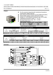
The Realtek RTL8201CL is a Fast Ethernet Phyceiver with selectable MII or SNI interface to the MAC <strong>chip</strong>. It<br />
provides the following features:<br />
! Sup<strong>port</strong>s MII/7-wire SNI (Serial Network<br />
Interface) interface<br />
! Sup<strong>port</strong>s <strong>10</strong>/<strong>10</strong>0Mbps operation<br />
! Sup<strong>port</strong>s half/full duplex operation<br />
! Sup<strong>port</strong> of twisted pair or Fiber mode output<br />
! IEEE 802.3/802.3u compliant<br />
! Sup<strong>port</strong>s IEEE 802.3u clause 28 auto<br />
negotiation<br />
! Sup<strong>port</strong>s power down mode<br />
! Sup<strong>port</strong>s operation under Link Down Power<br />
Saving mode<br />
! Sup<strong>port</strong>s Base Line Winder (BLW)<br />
compensation<br />
! Sup<strong>port</strong>s repeater mode<br />
! Speed/duplex/auto negotiation adjustable<br />
! 3.3V operation with 5V IO signal tolerance<br />
! Low operation power consumption and only<br />
need <strong>single</strong> supply 3.3V<br />
! Adaptive Equalization<br />
! 25MHz crystal/oscillator as clock source<br />
! Multiple network status LED sup<strong>port</strong><br />
! Flow control ability sup<strong>port</strong> to co-work with<br />
MAC (by MDC/MDIO)<br />
! 48 pin LQFP package<br />
2. General Description<br />
The RTL8201CL is a <strong>single</strong>-<strong>port</strong> Phyceiver with an MII (Media Independent Interface)/SNI (Serial Network<br />
Interface). It implements all <strong>10</strong>/<strong>10</strong>0M Ethernet Physical-layer functions including the Physical Coding Sublayer<br />
(PCS), Physical Medium Attachment (PMA), Twisted Pair Physical Medium Dependent Sublayer (TP-PMD),<br />
<strong>10</strong>Base-Tx Encoder/Decoder and Twisted Pair Media Access Unit (TPMAU). A PECL interface is sup<strong>port</strong>ed to<br />
connect with an external <strong>10</strong>0Base-FX fiber optical transceiver. The <strong>chip</strong> is fabricated with an advanced CMOS<br />
process to meet low voltage and low power requirements. Further more, it is developed with on <strong>chip</strong> Digital Signal<br />
Processing technology to ensure excellent performance under all operating conditions.<br />
The RTL8201CL can be used as a Network Interface Adapter, MAU, CNR, ACR, Ethernet Hub, and Ethernet<br />
Switch. Additionally, it can also be used in any embedded system with an Ethernet MAC that needs a UTP physical<br />
connection or Fiber PECL interface to external <strong>10</strong>0Base-FX optical transceiver module.<br />
2002-03-29 2<br />
Rev.1.0<br />
Tel: +49(0)234-9351135 · Fax: +49(0)234-9351137 E-MAIL: info@cornelius-consult.de http://www.cornelius-consult.de
RTL8201CL<br />
3. Block Diagram<br />
<strong>10</strong>0M<br />
MII<br />
Interface<br />
SNI<br />
Interface<br />
<strong>10</strong>/<strong>10</strong>0<br />
half/full<br />
Switch<br />
Logic<br />
5B 4B<br />
Decoder<br />
4B 5B<br />
Encoder<br />
Data<br />
Alignment<br />
Scrambler<br />
Descrambler<br />
RXD<br />
RXC 25M<br />
TXD<br />
TXC 25M<br />
<strong>10</strong>/<strong>10</strong>0M Auto-negotiation<br />
Control Logic<br />
Link pulse<br />
<strong>10</strong>M<br />
TXC<strong>10</strong><br />
TXD<strong>10</strong><br />
Manchester coded<br />
waveform<br />
<strong>10</strong>M Output waveform<br />
shaping<br />
RXC<strong>10</strong><br />
RXD<strong>10</strong><br />
Data Recovery<br />
Receive low pass filter<br />
TXC 25M<br />
TXD<br />
Parrallel<br />
to Serial<br />
TD+<br />
3 Level<br />
Driver<br />
TXO+<br />
TXO -<br />
Variable Current<br />
Baseline<br />
wander<br />
Correction<br />
Peak<br />
Detect<br />
MLT-3<br />
to NRZI<br />
3 Level<br />
Comparator<br />
Adaptive<br />
Equalizer<br />
RXIN+<br />
RXIN-<br />
RXC 25M<br />
RXD<br />
Serial to<br />
Parrallel<br />
ck<br />
data<br />
Slave<br />
PLL<br />
Control<br />
Voltage<br />
Master<br />
PPL<br />
25M<br />
2002-03-29 3<br />
Rev.1.0<br />
Tel: +49(0)234-9351135 · Fax: +49(0)234-9351137 E-MAIL: info@cornelius-consult.de http://www.cornelius-consult.de
RTL8201CL<br />
4. Pin Assignments<br />
RTL8201CL<br />
16. RXC<br />
1. COL<br />
2. TXEN<br />
3. TXD3<br />
4. TXD2<br />
5. TXD1<br />
6. TXD0<br />
7. TXC<br />
34. TPTX+<br />
33. TPTX-<br />
31. TPRX+<br />
30. TPRX-<br />
28. RTSET<br />
26. MDIO<br />
25. MDC<br />
37. ANE<br />
38. DUPLEX<br />
24. RXER<br />
/FXEN<br />
23. CRS<br />
39. SPEED<br />
40. RPTR<br />
22. RXDV<br />
21. RXD0<br />
41. LDPS<br />
20. RXD1<br />
43. ISOLATE<br />
44. MII/SNIB<br />
19. RXD2<br />
18. RXD3<br />
46. X1<br />
47. X2<br />
9. LED0/<br />
PHYAD0<br />
<strong>10</strong>. LED1/<br />
PHYAD1<br />
12. LED2/<br />
PHYAD2<br />
36. AVDD33<br />
35. AGND<br />
32. PWFBOUT<br />
29. AGND<br />
27. NC<br />
42. RESETB<br />
17. DGND<br />
45. DGND<br />
15. LED4/<br />
PHYAD4<br />
48. DVDD33<br />
14. DVDD33<br />
13. LED3/<br />
PHYAD3<br />
8. PWFBIN<br />
11. DGND<br />
2002-03-29 4<br />
Rev.1.0<br />
Tel: +49(0)234-9351135 · Fax: +49(0)234-9351137 E-MAIL: info@cornelius-consult.de http://www.cornelius-consult.de
5. Pin Description<br />
LI: Latched Input during Power up or Reset<br />
I/O: Bi-directional input and output<br />
I: Input<br />
O: Output<br />
P: Power<br />
5.1 MII Interface<br />
RTL8201CL<br />
Symbol Type Pin No. Description<br />
TXC O 7 Transmit Clock: This pin provides a continuous clock as a timing<br />
reference for TXD[3:0] and TXEN.<br />
TXEN I 2 Transmit Enable: The input signal indicates the presence of a valid<br />
nibble data on TXD[3:0].<br />
TXD[3:0] I 3, 4, 5, 6 Transmit Data: MAC will source TXD[0..3] synchronous with TXC<br />
when TXEN is asserted.<br />
RXC O 16 Receive Clock: This pin provides a continuous clock reference for<br />
RXDV and RXD[0..3] signals. RXC is 25MHz in the <strong>10</strong>0Mbps mode<br />
and 2.5Mhz in the <strong>10</strong>Mbps mode.<br />
COL O 1 Collision Detect: COL is asserted high when a collision is detected on the<br />
media.<br />
CRS O 23 Carrier Sense: This pin’s signal is asserted high if the media is not in IDEL<br />
state.<br />
RXDV O 22 Receive Data Valid: This pin’s signal is asserted high when received<br />
data is present on the RXD[3:0] lines; the signal is de-asserted at the<br />
end of the packet. The signal is valid on the rising of the RXC.<br />
RXD[3:0] O 18, 19, 20, 21 Receive Data: These are the four parallel receive data lines aligned<br />
on the nibble boundaries driven synchronously to the RXC for<br />
reception by the external physical unit (PHY).<br />
RXER/<br />
FXEN<br />
O/LI 24 Receive Error: if any 5B decode error occurs, such as invalid J/K,<br />
T/R, invalid symbol, this pin will go high.<br />
Fiber/UTP Enable: During power on reset, this pin status is latched<br />
to determine at which media mode to operate:<br />
1: Fiber mode<br />
0: UTP mode<br />
An internal weak pull low resistor, sets this to the default of UTP mode. It is<br />
possible to use an external 5.1KΩ pull high resistor to enable fiber mode.<br />
After power on, the pin operates as the Receive Error pin.<br />
MDC I 25 Management Data Clock: This pin provides a clock synchronous to<br />
MDIO, which may be asynchronous to the transmit TXC and receive<br />
RXC clocks. The clock rate can be up to 2.5MHz.<br />
MDIO I/O 26 Management Data Input/Output: This pin provides the bi-directional<br />
signal used to transfer management information.<br />
5.2 SNI (Serial Network Interface): <strong>10</strong>Mbps only<br />
Symbol Type Pin No. Description<br />
COL O 1 Collision Detect<br />
RXD0 O 21 Received Serial Data<br />
CRS O 23 Carrier Sense<br />
RXC O 16 Receive Clock: Resolved from received data<br />
TXD0 I 6 Transmit Serial Data<br />
TXC O 7 Transmit Clock: Generate by PHY<br />
TXEN I 2 Transmit Enable: For MAC to indicate transmit operation<br />
2002-03-29 5<br />
Rev.1.0<br />
Tel: +49(0)234-9351135 · Fax: +49(0)234-9351137 E-MAIL: info@cornelius-consult.de http://www.cornelius-consult.de
5.3 Clock Interface<br />
RTL8201CL<br />
Symbol Type Pin No. Description<br />
X2 O 47 25MHz Crystal Output: This pin provides the 25MHz crystal output.<br />
It must be left open when an external 25MHz oscillator drives X1.<br />
X1 I 46 25MHz Crystal Input: This pin provides the 25MHz crystal input. If a<br />
25MHz oscillator is used, connect X1 to the oscillator’s output. Refer<br />
to section 8.3 to obtain clock source specifications.<br />
5.4 <strong>10</strong>Mbps / <strong>10</strong>0Mbps Network Interface<br />
Symbol Type Pin No. Description<br />
O<br />
34<br />
O<br />
33<br />
TPTX+<br />
TPTX-<br />
Transmit Output: Differential transmit output pair shared by<br />
<strong>10</strong>0Base-TX, <strong>10</strong>0Base-FX and <strong>10</strong>Base-T modes. When configured as<br />
<strong>10</strong>0Base-TX, output is an MLT-3 encoded waveform. When configured<br />
as <strong>10</strong>0Base-FX, the output is pseudo-ECL level.<br />
RTSET I 28 Transmit Bias Resistor Connection: This pin should be pulled to<br />
GND by a 5.9KΩ (1%) resistor to define driving current for transmit<br />
DAC. The resistance value may be changed, depending on<br />
experimental results of the RTL8201CL.<br />
TPRX+<br />
TPRX-<br />
I<br />
I<br />
31<br />
30<br />
Receive Input: Differential receive input pair shared by <strong>10</strong>0Base-TX,<br />
<strong>10</strong>0Base-FX, and <strong>10</strong>Base-T modes.<br />
5.5 Device Configuration Interface<br />
Symbol Type Pin No. Description<br />
ISOLATE I 43 Set high to isolate the RTL8201CL from the MAC. This will also isolate the<br />
MDC/MDIO management interface. In this mode, the power consumption is<br />
minimum. This pin can be directly connected to GND or VCC.<br />
RPTR I 40 Set high to put the RTL8201CL into repeater mode. This pin can be<br />
directly connected to GND or VCC.<br />
SPEED LI 39 This pin is latched to input during a power on or reset condition. Set<br />
high to put the RTL8201CL into <strong>10</strong>0Mbps operation. This pin can be<br />
directly connected to GND or VCC.<br />
DUPLEX LI 38 This pin is latched to input during a power on or reset condition. Set<br />
high to enable full duplex. This pin can be directly connected to GND or<br />
VCC.<br />
ANE LI 37 This pin is latched to input during a power on or reset condition. Set<br />
high to enable Auto-negotiation mode, set low to force mode. This pin<br />
can be directly connected to GND or VCC.<br />
LDPS I 41 Set high to put the RTL8201CL into LDPS mode. This pin can be directly<br />
connected to GND or VCC. Refer to Section 7.7 for more information.<br />
MII/SNIB LI/O 44 This pin is latched to input during a power on or reset condition. Pull<br />
high to set the RTL8201CL into MII mode operation. Set low for SNI<br />
mode. This pin can be directly connected to GND or VCC.<br />
2002-03-29 6<br />
Rev.1.0<br />
Tel: +49(0)234-9351135 · Fax: +49(0)234-9351137 E-MAIL: info@cornelius-consult.de http://www.cornelius-consult.de
5.6 LED Interface/PHY Address Config<br />
RTL8201CL<br />
These five pins are latched into the RTL8201CL during power up reset to configure PHY address [0:4] used for MII<br />
management register interface. And then, in normal operation after initial reset, they are used as driving pins for<br />
status indication LED. The driving polarity, active low or active high, is determined by each latched status of the<br />
PHY address [4:0] during power-up reset. If latched status is High then it will be active low, and if latched status is<br />
Low then it will be active high. Refer to Section 7.5 for more information.<br />
Symbol Type Pin No. Description<br />
PHYAD0/<br />
LED0<br />
LI/O 9 PHY Address [0]<br />
Link LED: Active when linked.<br />
PHYAD1/<br />
LED1<br />
LI/O <strong>10</strong> PHY Address [1]<br />
Full Duplex LED: Active when in Full Duplex operation.<br />
PHYAD2/<br />
LED2<br />
LI/O 12 PHY Address [2]<br />
Link <strong>10</strong>/ACT LED: Active when linked in <strong>10</strong>Base-T mode, and<br />
PHYAD3/<br />
LED3<br />
PHYAD4/<br />
LED4<br />
blinking when transmitting or receiving data.<br />
LI/O 13 PHY Address [3]<br />
Link <strong>10</strong>0/ACT LED: Active when linked in <strong>10</strong>0Base-TX and blinking<br />
when transmitting or receiving data.<br />
LI/O 15 PHY Address [4]<br />
Collision LED: Active when collisions occur.<br />
5.7 Reset and other pins<br />
Symbol Type Pin No. Description<br />
RESETB I 42 RESETB: Set low to reset the <strong>chip</strong>. For a complete reset function,<br />
this pin must be asserted low for at least <strong>10</strong>ms.<br />
PWFBOUT O 32 Power Feedback Output: Be sure to connect a 22uF tantalum<br />
capacitor for frequency compensation and a 0.1uF capacitor for noise<br />
de-coupling. Then connect this pin through a ferrite bead to<br />
PWFBIN(pin8). The connection method is figured in section 7.11.<br />
PWFBIN I 8 Power Feedback Input: see the description of PWFBOUT.<br />
NC 27 Not connection<br />
5.8 Power and Ground pins<br />
Symbol Type Pin No. Description<br />
AVDD33 P 36 3.3V Analog power input: 3.3V power supply for analog circuit;<br />
should be well decoupled.<br />
AGND P 29,35 Analog Ground: Should be connected to a larger GND plane<br />
DVDD33 P 14,48 3.3V Digital Power input: 3.3V power supply for digital circuit.<br />
DGND P 11,17,45 Digital Ground: Should be connected to a larger GND plane.<br />
2002-03-29 7<br />
Rev.1.0<br />
Tel: +49(0)234-9351135 · Fax: +49(0)234-9351137 E-MAIL: info@cornelius-consult.de http://www.cornelius-consult.de
6. Register Descriptions<br />
This section will describe definitions and usage for each of the registers available in the RTL8201CL.<br />
6.1 Register 0 Basic Mode Control Register<br />
RTL8201CL<br />
Address Name Description/Usage Default/Attribute<br />
0: Reset This bit sets the status and control registers of<br />
0, RW<br />
the PHY in a default state. This bit is<br />
self-clearing.<br />
1 = software reset<br />
0 = normal operation<br />
0: Loopback This bit enables loopback of transmit data<br />
0, RW<br />
nibbles TXD to the receive data path.<br />
1 = enable loopback<br />
0 = normal operation<br />
0: Spd_Set This bit sets the network speed.<br />
1, RW<br />
1 = <strong>10</strong>0Mbps<br />
0 = <strong>10</strong>Mbps<br />
After completing auto negotiation, this bit will<br />
reflect the duplex status.(1: Full duplex, 0: Half<br />
duplex)<br />
When <strong>10</strong>0Base-FX mode is enabled, this bit=1<br />
and is read only.<br />
0: Auto This bit enables/disables the Nway<br />
1, RW<br />
Negotiation<br />
Enable<br />
auto-negotiation function.<br />
1 = enable auto-negotiation; bits 0: and<br />
0: will be ignored.<br />
0 = disable auto-negotiation; bits 0: and<br />
0: will determine the link speed and the data<br />
transfer mode, respectively.<br />
When <strong>10</strong>0Base-FX mode is enabled, this bit=0<br />
and is read only.<br />
0: Power Down This bit turns down the power of the PHY <strong>chip</strong><br />
including internal crystal oscillator circuit. The<br />
MDC, MDIO is still alive for accessing the MAC.<br />
1 = power down<br />
0 = normal operation<br />
0, RW<br />
0: Reserved<br />
0: Restart Auto<br />
Negotiation<br />
This bits allows the Nway auto-negotiation<br />
function to be reset.<br />
1 = re-start auto-negotiation<br />
0 = normal operation<br />
0: Duplex Mode This bit sets the duplex mode if auto negotiation<br />
is disabled (bit 0:=0)<br />
1 = full duplex<br />
0 = half duplex<br />
After completing auto negotiation, this bit will<br />
reflect the duplex status.(1: Full duplex, 0: Half<br />
duplex)<br />
0: Reserved<br />
0, RW<br />
1, RW<br />
2002-03-29 8<br />
Rev.1.0<br />
Tel: +49(0)234-9351135 · Fax: +49(0)234-9351137 E-MAIL: info@cornelius-consult.de http://www.cornelius-consult.de
6.2 Register 1 Basic Mode Status Register<br />
Address Name Description/Usage Default/Attribute<br />
1: <strong>10</strong>0Base-T4 1 = enable <strong>10</strong>0Base-T4 sup<strong>port</strong><br />
0, RO<br />
0 = suppress <strong>10</strong>0Base-T4 sup<strong>port</strong><br />
1: <strong>10</strong>0Base_TX_ 1 = enable <strong>10</strong>0Base-TX full duplex sup<strong>port</strong><br />
1, RO<br />
FD 0 = suppress <strong>10</strong>0Base-TX full duplex sup<strong>port</strong><br />
1: <strong>10</strong>0BASE_TX_ 1 = enable <strong>10</strong>0Base-TX half duplex sup<strong>port</strong><br />
1, RO<br />
HD 0 = suppress <strong>10</strong>0Base-TX half duplex sup<strong>port</strong><br />
1: <strong>10</strong>Base_T_FD 1 = enable <strong>10</strong>Base-T full duplex sup<strong>port</strong><br />
1, RO<br />
0 = suppress <strong>10</strong>Base-T full duplex sup<strong>port</strong><br />
1: <strong>10</strong>_Base_T_H 1 = enable <strong>10</strong>Base-T half duplex sup<strong>port</strong><br />
1, RO<br />
D 0 = suppress <strong>10</strong>Base-T half duplex sup<strong>port</strong><br />
1: Reserved<br />
1: MF Preamble The RTL8201CL will accept management<br />
1, RO<br />
Suppression frames with preamble suppressed. The<br />
RTL8201CL accepts management frames<br />
without preamble. A Minimum of 32 preamble<br />
bits are required for the first SMI read/write<br />
transaction after reset. One idle bit is required<br />
between any two management transactions as<br />
1: Auto<br />
Negotiation<br />
Complete<br />
per IEEE802.3u specifications<br />
1 = auto-negotiation process completed<br />
0 = auto-negotiation process not completed<br />
1: Remote Fault 1 = remote fault condition detected (cleared on<br />
read)<br />
0 = no remote fault condition detected<br />
When in <strong>10</strong>0Base-FX mode, this bit means an<br />
in-band signal Far-End-Fault is detected. Refer<br />
to Section 7.11.<br />
1: Auto<br />
Negotiation<br />
1 = Link had not been experienced fail state<br />
0 = Link had been experienced fail state<br />
1: Link Status 1 = valid link established<br />
0 = no valid link established<br />
1: Jabber Detect 1 = jabber condition detected<br />
0 = no jabber condition detected<br />
1: Extended 1 = extended register capability<br />
Capability 0 = basic register capability only<br />
0, RO<br />
0, RO<br />
1, RO<br />
0, RO<br />
0, RO<br />
1, RO<br />
RTL8201CL<br />
6.3. Register 2 PHY Identifier Register 1<br />
Address Name Description/Usage Default/Attribute<br />
2: PHYID1 PHY identifier ID for software recognize<br />
0000, RO<br />
RTL8201CL<br />
6.4. Register 3 PHY Identifier Register 2<br />
Address Name Description/Usage Default/Attribute<br />
3: PHYID2 PHY identifier ID for software recognize<br />
8201, RO<br />
RTL8201<br />
2002-03-29 9<br />
Rev.1.0<br />
Tel: +49(0)234-9351135 · Fax: +49(0)234-9351137 E-MAIL: info@cornelius-consult.de http://www.cornelius-consult.de
RTL8201CL<br />
6.5. Register 4 Auto-negotiation Advertisement<br />
Register(ANAR)<br />
This register contains the advertised abilities of this device as they will be transmitted to its link partner during<br />
Auto-negotiation.<br />
Address Name Description/Usage Default/Attribute<br />
4: NP Next Page bit.<br />
0, RO<br />
0 = transmitting the primary capability data page<br />
1 = transmitting the protocol specific data page<br />
4: ACK 1 = acknowledge reception of link partner capability<br />
0, RO<br />
data word<br />
0 = do not acknowledge reception<br />
4: RF 1 = advertise remote fault detection capability<br />
0, RW<br />
0 = do not advertise remote fault detection capability<br />
4: Reserved<br />
4: TFC 1 = TX flow control is sup<strong>port</strong>ed by local node<br />
0, RW<br />
0 = TX flow control is NOT sup<strong>port</strong>ed by local node<br />
4: Pause 1 = RX flow control is sup<strong>port</strong>ed by local node<br />
0, RW<br />
0 = RX flow control is NOT sup<strong>port</strong>ed by local node<br />
4: T4 1 = <strong>10</strong>0Base-T4 is sup<strong>port</strong>ed by local node<br />
0, RO<br />
0 = <strong>10</strong>0Base-T4 not sup<strong>port</strong>ed by local node<br />
4: TXFD 1 = <strong>10</strong>0Base-TX full duplex is sup<strong>port</strong>ed by local node<br />
1, RW<br />
0 = <strong>10</strong>0Base-TX full duplex not sup<strong>port</strong>ed by local node<br />
4: TX 1 = <strong>10</strong>0Base-TX is sup<strong>port</strong>ed by local node<br />
1, RW<br />
0 = <strong>10</strong>0Base-TX not sup<strong>port</strong>ed by local node<br />
4: <strong>10</strong>FD 1 = <strong>10</strong>Base-T full duplex sup<strong>port</strong>ed by local node<br />
1, RW<br />
0 = <strong>10</strong>Base-T full duplex not sup<strong>port</strong>ed by local node<br />
4: <strong>10</strong> 1 = <strong>10</strong>Base-T is sup<strong>port</strong>ed by local node<br />
1, RW<br />
0 = <strong>10</strong>Base-T not sup<strong>port</strong>ed by local node<br />
4: Selector Binary encoded selector sup<strong>port</strong>ed by this node.<br />
Currently only CSMA/CD is specified. No<br />
other protocols are sup<strong>port</strong>ed.<br />
, RW<br />
6.6 Register 5 Auto-Negotiation Link Partner Ability<br />
Register(ANLPAR)<br />
This register contains the advertised abilities of the Link Partner as received during Auto-negotiation. The content<br />
changes after the successful Auto-negotiation if Next-pages are sup<strong>port</strong>ed.<br />
Address Name Description/Usage Default/Attribute<br />
5: NP Next Page bit.<br />
0, RO<br />
0 = transmitting the primary capability data page<br />
1 = transmitting the protocol specific data page<br />
5: ACK 1 = link partner acknowledges reception of local<br />
0, RO<br />
node’s capability data word<br />
0 = no acknowledgement<br />
5: RF 1 = link partner is indicating a remote fault<br />
0, RO<br />
0 = link partner does not indicate a remote fault<br />
5: Reserved<br />
5: TFC 1 = TX flow control is sup<strong>port</strong>ed by Link partner<br />
0, RO<br />
0 = TX flow control is NOT sup<strong>port</strong>ed by Link partner<br />
5: Pause 1 = RX flow control is sup<strong>port</strong>ed by Link partner<br />
0, RO<br />
0 = RX flow control is NOT sup<strong>port</strong>ed by Link partner<br />
5: T4 1 = <strong>10</strong>0Base-T4 is sup<strong>port</strong>ed by link partner<br />
0 = <strong>10</strong>0Base-T4 not sup<strong>port</strong>ed by link partner<br />
0, RO<br />
2002-03-29 <strong>10</strong><br />
Rev.1.0<br />
Tel: +49(0)234-9351135 · Fax: +49(0)234-9351137 E-MAIL: info@cornelius-consult.de http://www.cornelius-consult.de
RTL8201CL<br />
5: TXFD 1 = <strong>10</strong>0Base-TX full duplex is sup<strong>port</strong>ed by link partner<br />
0 = <strong>10</strong>0Base-TX full duplex not sup<strong>port</strong>ed by link partner<br />
5: <strong>10</strong>0BASE-TX 1 = <strong>10</strong>0Base-TX is sup<strong>port</strong>ed by link partner<br />
0 = <strong>10</strong>0Base-TX not sup<strong>port</strong>ed by link partner<br />
This bit will also be set after the link in <strong>10</strong>0Base is<br />
established by parallel detection.<br />
5: <strong>10</strong>FD 1 = <strong>10</strong>Base-T full duplex is sup<strong>port</strong>ed by link partner<br />
0 = <strong>10</strong>Base-T full duplex not sup<strong>port</strong>ed by link partner<br />
5: <strong>10</strong>Base-T 1 = <strong>10</strong>Base-T is sup<strong>port</strong>ed by link partner<br />
0 = <strong>10</strong>Base-T not sup<strong>port</strong>ed by link partner<br />
This bit will also be set after the link in <strong>10</strong>Base is<br />
established by parallel detection.<br />
5: Selector Link Partner’s binary encoded node selector<br />
Currently only CSMA/CD is specified<br />
0, RO<br />
1, RO<br />
0, RO<br />
0, RO<br />
, RO<br />
6.7 Register 6 Auto-negotiation Expansion Register(ANER)<br />
This register contains additional status for NWay auto-negotiation.<br />
Address Name Description/Usage Default/Attribute<br />
6: Reserved This bit is always set to 0.<br />
6: MLF Status indicating if a multiple link fault has<br />
0, RO<br />
occurred.<br />
1 = fault occurred<br />
0 = no fault occurred<br />
6: LP_NP_ABLE Status indicating if the link partner sup<strong>port</strong>s Next<br />
0, RO<br />
Page negotiation.<br />
1 = sup<strong>port</strong>ed<br />
0 = not sup<strong>port</strong>ed<br />
6: NP_ABLE This bit indicates if the local node is able to send<br />
0, RO<br />
additional Next Pages.<br />
6: PAGE_RX This bit is set when a new Link Code Word Page<br />
0, RO<br />
has been received. It is automatically cleared<br />
when the auto-negotiation link partner’s ability<br />
register (register 5) is read by management.<br />
6: LP_NW_ABLE 1 = link partner sup<strong>port</strong>s Nway auto-negotiation. 0, RO<br />
6.8 Register 16 Nway Setup Register(NSR)<br />
Address Name Description/Usage Default/Attribute<br />
16: Reserved<br />
16: ENNWLE 1 = LED4 Pin indicates linkpulse 0, RW<br />
16: Testfun 1 = Auto-neg speeds up internal timer 0, RW<br />
16: NWLPBK 1 = set Nway to loopback mode. 0, RW<br />
16: Reserved<br />
16: FLAGABD 1 = Auto-neg experienced ability detect state 0, RO<br />
16: FLAGPDF 1 = Auto-neg experienced parallel detection fault<br />
0, RO<br />
state<br />
16: FLAGLSC 1 = Auto-neg experienced link status check state 0, RO<br />
2002-03-29 11<br />
Rev.1.0<br />
Tel: +49(0)234-9351135 · Fax: +49(0)234-9351137 E-MAIL: info@cornelius-consult.de http://www.cornelius-consult.de
RTL8201CL<br />
6.9 Register 17 Loopback, Bypass, Receiver Error Mask<br />
Register(LBREMR)<br />
Address Name Description/Usage Default/Attribute<br />
17: RPTR Set to 1 to put the RTL8201CL into repeater<br />
0, RW<br />
mode<br />
17: BP_4B5B Assertion of this bit allows bypassing of the<br />
0, RW<br />
4B/5B & 5B/4B encoder.<br />
17: BP_SCR Assertion of this bit allows bypassing of the<br />
0, RW<br />
scrambler/descrambler.<br />
17: LDPS Set to 1 to enable Link Down Power Saving<br />
0, RW<br />
mode<br />
17: AnalogOFF Set to 1 to power down analog function of<br />
0, RW<br />
transmitter and receiver.<br />
17: Reserve Reserve<br />
17: LB Set to 1 to enablePCS Loopback 0, RW<br />
17: F_Link_<strong>10</strong>B Used to logic force good link in <strong>10</strong>Mbps for<br />
1, RW<br />
diagnostic purposes. (Assert 0 to active)<br />
17: F_Link_<strong>10</strong>0B Used to logic force good link in <strong>10</strong>0Mbps for<br />
1, RW<br />
diagnostic purposes. (Assert 1 to active)<br />
17: JBEN Set to 1 to enable Jabber Function in <strong>10</strong>BT 0, RW<br />
17: CODE_err Assertion of this bit causes a code error<br />
0, RW<br />
detection to be re<strong>port</strong>ed.<br />
17: PME_err Assertion of this bit causes a pre-mature end<br />
0, RW<br />
error detection to be re<strong>port</strong>ed.<br />
17: LINK_err Assertion of this bit causes a link error detection<br />
0, RW<br />
to be re<strong>port</strong>ed.<br />
17: PKT_err Assertion of this bit causes a detection of packet<br />
0, RW<br />
errors due to 722 ms time-out to be re<strong>port</strong>ed.<br />
17: FXMODE This bit indicates status whether Fiber Mode is<br />
0, R<br />
Enabled<br />
17: RMIIMODE This bit indicates status whether RMII mode is<br />
Enabled<br />
0, R<br />
6.<strong>10</strong> Register 18 RX_ER Counter(REC)<br />
Address Name Description/Usage Default/Attribute<br />
18: RXERCNT This 16-bit counter increments by 1 for each<br />
H’[0000],<br />
valid packet received.<br />
RW<br />
6.11 Register 19 SNR Display Register<br />
Address Name Description/Usage Default/Attribute<br />
19: Reserved Please do not alternate this field with Realtek’s<br />
approval. (Test Mode Purpose for Realtek Only)<br />
19: SNR This 4-bit shows SNR value [000], RW<br />
2002-03-29 12<br />
Rev.1.0<br />
Tel: +49(0)234-9351135 · Fax: +49(0)234-9351137 E-MAIL: info@cornelius-consult.de http://www.cornelius-consult.de
6.12 Register 25 Test Register<br />
Address Name Description/Usage Default/ Attribute<br />
25 Test Reserved for internal testing R/W<br />
25: PHYAD[4:0] Reflects the PHY address defined by external<br />
RO<br />
PHY address configuration pins<br />
25 Test Reserved for internal testing RO<br />
25 LINK<strong>10</strong> 1: Link established in <strong>10</strong>Base OK<br />
RO<br />
0: No link established in <strong>10</strong>Base<br />
25 LINK<strong>10</strong>0 1: Link established in <strong>10</strong>0Base OK<br />
0: No link established in <strong>10</strong>0Base<br />
RO<br />
RTL8201CL<br />
2002-03-29 13<br />
Rev.1.0<br />
Tel: +49(0)234-9351135 · Fax: +49(0)234-9351137 E-MAIL: info@cornelius-consult.de http://www.cornelius-consult.de
7. Functional Description<br />
RTL8201CL<br />
The RTL8201CL Phyceiver is a physical layer device that integrates <strong>10</strong>Base-T and <strong>10</strong>0Base-TX functions and<br />
some extra power manage features into a 48 pin <strong>single</strong> <strong>chip</strong> which is used in <strong>10</strong>/<strong>10</strong>0 Fast Ethernet applications.<br />
This device sup<strong>port</strong>s the following functions:<br />
# MII interface with MDC/MDIO SMI management interface to communicate with MAC<br />
# IEEE 802.3u clause 28 Auto-Negotiation ability<br />
# Flow control ability sup<strong>port</strong> to cooperate with MAC<br />
# Speed, duplex, auto-negotiation ability configurable by hard wire or MDC/MDIO.<br />
# Flexible LED configuration.<br />
# 7-wire SNI(Serial Network Interface) sup<strong>port</strong>, works only on <strong>10</strong>Mbps mode.<br />
# Power Down mode sup<strong>port</strong><br />
# 4B/5B transform<br />
# Scrambling/De-scrambling<br />
# NRZ to NRZI, NRZI to MLT3<br />
# Manchester Encode and Decode for <strong>10</strong> BaseT operation<br />
# Clock and Data recovery<br />
# Adaptive Equalization<br />
# Far End Fault Indication (FEFI) in fiber mode<br />
7.1 MII and Management Interface<br />
7.1.1 Data Transition<br />
To set the RTL8201CL for MII mode operation, pull MII/SNIB pin high and properly set the ANE, SPEED, and<br />
DUPLEX pins.<br />
The MII (Media Independent Interface) is an 18-signal interface which is described in IEEE 802.3u supplying a<br />
standard interface between PHY and MAC layer. This interface operates in two frequencies – 25Mhz and 2.5Mhz<br />
to sup<strong>port</strong> <strong>10</strong>0Mbps/<strong>10</strong>Mbps bandwidth for both transmit and receive functions. While transmitting packets, the<br />
MAC will first assert the TXEN signal and change byte data into 4 bits nibble and pass to the PHY by TXD[0..3].<br />
PHY will sample TXD[0..3] synchronously with TXC — the transmit clock signal supplied by PHY – during the<br />
interval TXEN is asserted. While receiving a packet, the PHY will assert the RXEN signal, pass the received nibble<br />
data RXD[0..3] clocked by RXC, which is recovered from the received data. CRS and COL signals are used for<br />
collision detection and handling.<br />
In <strong>10</strong>0Base-TX mode, when decoded signal in 5B is not IDLE, the CRS signal will assert and when 5B is<br />
recognized as IDLE it will be de-asserted. In <strong>10</strong>Base-T mode, CRS will assert when the <strong>10</strong>M preamble been<br />
confirmed and will be de-asserted when the IDLE pattern been confirmed.<br />
The RXDV signal will be asserted when decoded 5B are /J/K/and will be de-asserted if the 5B are /T/R/or IDLE in<br />
<strong>10</strong>0Mbps mode. In <strong>10</strong>Mbps mode, the RXDV signal is the same as the CRS signal.<br />
The RXER (Receive Error) signal will be asserted if any 5B decode errors occur such as invalid J/K, T/R, invalid<br />
symbol, this pin will go high for one or more clock period to indicate to the reconciliation sublayer that an error was<br />
detected somewhere in the frame.<br />
The RTL8201CL does not use the TXER signal and will not affect the transmit function.<br />
2002-03-29 14<br />
Rev.1.0<br />
Tel: +49(0)234-9351135 · Fax: +49(0)234-9351137 E-MAIL: info@cornelius-consult.de http://www.cornelius-consult.de
RTL8201CL<br />
7.1.2 Serial Management<br />
The MAC layer device can use the MDC/MDIO management interface to control a maximum of 31 RTL8201CL<br />
devices, configured with different PHY addresses (00001b to 11111b). During a hardware reset, the logic levels of<br />
pins 9,<strong>10</strong>,12,13,15 are latched into the RTL8201CL to be set as the PHY address for serial management interface<br />
communication. Setting the PHY address to 00000b will put the RTL8201CL into power down mode. The read and<br />
write frame structure for the management interface follows.<br />
MDC<br />
MDIO<br />
32 1s<br />
0 1 0 1<br />
A4<br />
A3<br />
A2<br />
A1<br />
A0<br />
R4<br />
R3<br />
R2<br />
R1<br />
R0<br />
1 0<br />
D15<br />
D14<br />
D13<br />
D12<br />
D11<br />
D<strong>10</strong><br />
D9<br />
D8<br />
D7<br />
D6<br />
D5<br />
D4<br />
D3<br />
D2<br />
D1<br />
D0<br />
Preamble<br />
ST<br />
OP<br />
PHYAD[4:0]<br />
REGAD[4:0]<br />
TA<br />
DATA<br />
Idle<br />
MDIO is sourced by MAC. Clock data into PHY on rising edge of MDC<br />
Write Cycle<br />
MDC<br />
MDIO<br />
32 1s<br />
Z<br />
0 1 1 0<br />
A4<br />
A3<br />
A2<br />
A1<br />
A0<br />
R4<br />
R3<br />
R2<br />
R1<br />
R0<br />
0<br />
D15<br />
D14<br />
D13<br />
D12<br />
D11<br />
D<strong>10</strong><br />
D9<br />
D8<br />
D7<br />
D6<br />
D5<br />
D4<br />
D3<br />
D2<br />
D1<br />
D0<br />
Preamble<br />
ST<br />
OP<br />
PHYAD[4:0]<br />
REGAD[4:0]<br />
TA<br />
DATA<br />
Idle<br />
MDIO is sourced by MAC. Clock data into PHY on rising edge of MDC<br />
Read Cycle<br />
MDIO is sourced by PHY. Clock data from PHY on rising edge of MDC<br />
Preamble 32 contiguous logic '1's sent by the MAC on MDIO along with 32 corresponding cycles on MDC. This<br />
provides synchronization for the PHY.<br />
ST Start of Frame. Indicated by a 01 pattern.<br />
OP Operation code. Read = <strong>10</strong>. Write = 01.<br />
PHYAD PHY Address. Up to 31 PHYs can be connected to one MAC. This 5 bit field selects which PHY the<br />
frame is directed to.<br />
REGAD Register Address. This is a 5 bit field that selects which one of the 32 registers of the PHY this<br />
operation refers to.<br />
TA Turnaround. This is a two bit time spacing between the register address and the data field of a frame<br />
to avoid contention during a read transaction. For a read transaction, both the STA and the PHY shall<br />
remain in a high-impedance state for the first bit time of the turnaround. The PHY shall drive a zero<br />
bit during the second bit time of the turnaround of a read transaction.<br />
DATA Data. These are the 16 bits of Data.<br />
IDLE Idle Condition, not actually part of the management frame. This is a high impedance state.<br />
Electrically, the PHY's pull-up resistor will pull the MDIO line to a logic one.<br />
2002-03-29 15<br />
Rev.1.0<br />
Tel: +49(0)234-9351135 · Fax: +49(0)234-9351137 E-MAIL: info@cornelius-consult.de http://www.cornelius-consult.de
RTL8201CL<br />
7.2 Auto-negotiation and Parallel Detection<br />
The RTL8201CL sup<strong>port</strong>s IEEE 802.3u clause 28 Auto-negotiation operation which can cooperate with other<br />
transceivers sup<strong>port</strong>ing auto-negotiation. By this mechanism, the RTL8201CL can auto detect the link partner’s<br />
ability and determine the highest speed/duplex configuration and transmit/receive in this configuration. If the link<br />
partner does not sup<strong>port</strong> Auto-negotiation, then the RTL8201CL will enable half duplex mode and enter parallel<br />
detection. The RTL8201CL will default to transmit FLP and wait for the link partner to respond. If the RTL8201CL<br />
receives FPL, then the auto-negotiation process will go on. If it receives NLP, then the RTL8201CL will change to<br />
<strong>10</strong>Mbps and half duplex mode. If it receives a <strong>10</strong>0Mbps IDLE pattern, it will change to <strong>10</strong>0Mbps and half duplex<br />
mode.<br />
To enable the auto-negotiation mode operation on the RTL8201CL, just pull the ANE pin high. And the SPEED pin<br />
and DUPLEX pin will set the ability content of auto-negotiation register. The auto-negotiation mode can be<br />
externally disabled by pulling the ANE pin low. In this case, the SPEED pin and DUXPLEX pin will change the media<br />
configuration of the RTL8201CL.<br />
Below is a list for all configurations of the ANE/SPEED/DUPLEX pins and their operation in Fiber or UTP mode.<br />
Select Medium type and interface mode to MAC<br />
FX<br />
(pin 24)<br />
MII/SNIB<br />
(pin 44)<br />
L H UTP mode and MII interface<br />
L L UTP mode and SNI interface<br />
H X Fiber mode and MII interface<br />
Operation mode<br />
UTP mode and MII interface<br />
ANE<br />
(Pin 37)<br />
SPEED<br />
(Pin 39)<br />
DUPLEX<br />
(Pin 38)<br />
Operation<br />
H L L<br />
Auto-negotiation enable, the ability field does not sup<strong>port</strong> <strong>10</strong>0Mbps and full<br />
duplex mode operation<br />
H L H Auto-negotiation enable, the ability field does not sup<strong>port</strong> <strong>10</strong>0Mbps operation<br />
H H L<br />
H H H<br />
L L L<br />
L L H<br />
L H L<br />
L H H<br />
Auto-negotiation enable, the ability field does not sup<strong>port</strong> full duplex mode<br />
operation<br />
Default setup, auto-negotiation enable, the RTL8201CL will sup<strong>port</strong> <strong>10</strong>BaseT<br />
/<strong>10</strong>0BaseTX, half/full duplex mode operation<br />
Auto-negotiation disable, force the RTL8201CL into <strong>10</strong>BaseT and half duplex<br />
mode<br />
Auto-negotiation disable, force the RTL8201CL into <strong>10</strong>BaseT and full duplex<br />
mode<br />
Auto-negotiation disable, force the RTL8201CL into <strong>10</strong>0BaseTX and half duplex<br />
mode<br />
Auto-negotiation disable, force the RTL8201CL into <strong>10</strong>0BaseTX and full duplex<br />
mode<br />
UTP mode and SNI interface<br />
SNI interface to MAC. It only works in <strong>10</strong>Base-T when the SNI interface is enabled.<br />
ANE SPEED DUPLEX<br />
Operation<br />
(Pin 37) (Pin 39) (Pin 38)<br />
X X L The duplex pin is pulled low to sup<strong>port</strong> the <strong>10</strong>Base-T half duplex<br />
function.<strong>10</strong>Base-T half duplex is the specified default mode in the SNI<br />
interface.<br />
X X H The RTL8201CL also sup<strong>port</strong>s full duplex in SNI mode. The duplex pin is<br />
pulled high to sup<strong>port</strong> <strong>10</strong>Base-T full duplex function.<br />
2002-03-29 16<br />
Rev.1.0<br />
Tel: +49(0)234-9351135 · Fax: +49(0)234-9351137 E-MAIL: info@cornelius-consult.de http://www.cornelius-consult.de
RTL8201CL<br />
Fiber mode and MII interface<br />
The RTL8201CL only sup<strong>port</strong>s <strong>10</strong>0Base-FX when Fiber mode is enabled. Ignore ANE and Speed hardwire<br />
configuration.<br />
ANE SPEED DUPLEX<br />
Operation<br />
(Pin 37) (Pin 39) (Pin 38)<br />
X X H The duplex pin is pulled high to sup<strong>port</strong> <strong>10</strong>0Base-FX full duplex function.<br />
X X L The duplex pin is pulled low to sup<strong>port</strong> <strong>10</strong>0Base-FX half duplex function.<br />
7.3 Flow control sup<strong>port</strong><br />
The RTL8201CL sup<strong>port</strong>s flow control indications. The MAC can program the MII register to indicate to the PHY<br />
that flow control is sup<strong>port</strong>ed. When MAC sup<strong>port</strong>s the Flow Control mechanism, setting bit <strong>10</strong> of the ANAR<br />
register by MDC/MDIO SMI interface, then the RTL8201CL will add the ability to its N-Way ability. If the Link<br />
partner also sup<strong>port</strong>s Flow Control, then the RTL8201CL can recognize the Link partner’s N-Way ability by<br />
examining bit <strong>10</strong> of ANLPAR (register 5).<br />
7.4 Hardware Configuration and Auto-negotiation<br />
This section describes methods to configure the RTL8201CL and set the auto-negotiation mode. This list will show<br />
the various pins and their setting to provide the desired result.<br />
1) Isolate pin: Set high to isolate the RTL8201CL from the MAC. This will also isolate the MDC/MDIO<br />
management interface. In this mode, power consumption is minimum. Please refer to the section covering<br />
Isolation mode and Power Down mode.<br />
2) RPTR pin: Pull high to set the RTL8201CL into repeater mode. This pin is pulled low by default. Please refer to<br />
the section covering Repeater mode operation.<br />
3) LDPS pin: Pull high to set the RTL8201CL into LDPS mode. This pin is pulled low by default. Please refer to<br />
the section covering Power Down mode and Link Down Power Saving.<br />
4) MII/SNIB: Pull high to set RTL8201CL into MII mode operation, which is the default mode for the RTL8201.<br />
This pin pulled low will set the RTL8201CL into SNI mode operation. When set to SNI mode, the RTL8201CL<br />
will work at <strong>10</strong>Mbps. Please refer to the section covering Serial Network Interface for more detail information.<br />
5) ANE pin: Pull high to enable Auto-negotiation (default). Pull low to disable auto-negotiation and activate the<br />
parallel detection mechanism. Please refer to the section covering Auto-negotiation and Parallel Detection<br />
6) Speed pin: When ANE is pulled high, the ability to adjust speed is setup. When ANE is pulled low, pull this pin<br />
low to force <strong>10</strong>Mbps operation and high to force <strong>10</strong>0Mbps operation. Please refer to the section on<br />
Auto-negotiation and Parallel Detection.<br />
7) DUPLEX pin: When ANE is pulled high, the ability to adjust the DUPLEX pin will be setup. When ANE is pulled<br />
low, pull this pin low to force half duplex and high to force full duplex operation. Please refer to the section<br />
covering Auto-negotiation and Parallel Detection.<br />
2002-03-29 17<br />
Rev.1.0<br />
Tel: +49(0)234-9351135 · Fax: +49(0)234-9351137 E-MAIL: info@cornelius-consult.de http://www.cornelius-consult.de
RTL8201CL<br />
7.5 LED and PHY Address Configuration<br />
In order to reduce the pin count on the RTL8201CL, the LED pins are duplexed with the PHY address pins.<br />
Because the PHYAD strap options share the LED output pins, the external combinations required for strapping and<br />
LED usage must be considered in order to avoid contention. Specifically, when the LED outputs are used to drive<br />
LEDs directly, the active state of each output driver is dependent on the logic level sampled by the corresponding<br />
PHYAD input upon power-up/reset. For example, as following left figure shows, if a given PHYAD input is<br />
resistively pulled high then the corresponding output will be configured as an active low driver. As right figure<br />
shows, if a given PHYAD input is resistively pulled low then the corresponding output will be configured as an<br />
active high driver. The PHY address configuration pins should not be connected to GND or VCC directly, but must<br />
be pulled high or low through a resistor (ex 5.1KΩ). If no LED indications are needed, the components of the LED<br />
path (LED+5<strong>10</strong>Ω) can be removed.<br />
VCC<br />
LED<br />
PAD[0:4]/<br />
LED[0:4]<br />
LED<br />
5.1K ohm<br />
5<strong>10</strong> ohm<br />
5<strong>10</strong> ohm<br />
5.1K ohm<br />
PAD[0:4]/<br />
LED[0:4]<br />
PHY address[:] = logic 1 PHY address[:] = logic 0<br />
LED indication = active low<br />
LED indication = active High<br />
LED0<br />
LED1<br />
LED2<br />
LED3<br />
LED4<br />
Link<br />
Full Duplex<br />
Link <strong>10</strong>-Activity<br />
Link <strong>10</strong>0-Activity<br />
Collision<br />
7.6 Serial Network Interface<br />
LED Definitions<br />
The RTL8201CL also sup<strong>port</strong>s the traditional 7-wire serial interface to cooperate with legacy MACs or embedded<br />
systems. To setup for this mode of operation, pull the MII/SNIB pin low and by doing so, the RTL8201CL will ignore<br />
the setup of the ANE and SPEED pins. In this mode, the RTL8201CL will set the default to work in <strong>10</strong>Mbps and<br />
Half-duplex mode. But the RTL8201CL may also sup<strong>port</strong> full duplex mode operation if the DUPLEX pin has been<br />
pulled high.<br />
This interface consists of <strong>10</strong>Mbps transmit and receive clock generated by PHY, <strong>10</strong>Mbps transmit and receive<br />
serial data, transmit enable, collision detect, and carry sense signals.<br />
7.7 Power Down, Link Down, Power Saving, and Isolation Modes<br />
The RTL8201CL supplies 4 kinds of Power Saving mode operation. This section will discuss all four, including how<br />
to implement each mode. The first three modes are configured through software, and the fourth through hardware.<br />
1) Analog off: Setting bit 11 of register 17 to 1 will put the RTL8201CL into analog off state. In analog off state,<br />
the RTL8201CL will power down all analog functions such as transmit, receive, PLL, etc. However, the internal<br />
25MHz crystal oscillator will not be powered down. The digital functions in this mode are still available which<br />
2002-03-29 18<br />
Rev.1.0<br />
Tel: +49(0)234-9351135 · Fax: +49(0)234-9351137 E-MAIL: info@cornelius-consult.de http://www.cornelius-consult.de
RTL8201CL<br />
allows reacquisition of analog functions.<br />
2) LDPS mode: Setting bit 12 of register 17 to 1 or pulling the LDPS pin high will put the RTL8201CL into LDPS<br />
(Link Down Power Saving) mode. In LDPS mode, the RTL8201CL will detect the link status to decide whether<br />
or not to turn off the transmit function. If the link is off, FLP or <strong>10</strong>0Mbps IDLE/<strong>10</strong>Mbps NLP will not be<br />
transmitted. However, some signals similar to NLP will be transmitted. Once the receiver detects any leveled<br />
signals, it will stop the signal and transmit FLP or <strong>10</strong>0Mbps IDLE/<strong>10</strong>Mbps NLP again. This may save about<br />
60%~80% power when the link is down.<br />
3) PWD mode: Setting bit 11 of register 0 to 1 will put the RTL8201CL into power down mode. This is the<br />
maximum power saving mode while the RTL8201CL is still alive. In PWD mode, the RTL8201CL will turn off all<br />
analog/digital functions except the MDC/MDIO management interface. Therefore, if the RTL8201CL is put into<br />
PWD mode and the MAC wants to recall the PHY, it must create the MDC/MDIO timing by itself (this is done by<br />
software).<br />
4) Isolation mode: This mode is different from the three previous software configured power saving modes. This<br />
mode is configured by hardware pin 43. Setting pin 43 high will isolate the RTL8201CL from the Media Access<br />
Controller (MAC) and the MDC/MDIO management interface. In this mode, power consumption is minimum.<br />
7.8 Media Interface<br />
7.8.1 <strong>10</strong>0Base TX<br />
1) <strong>10</strong>0Base-TX Transmit Function: The <strong>10</strong>0Base-TX transmit function is performed as follows: First the transmit<br />
data in 4 bit nibbles (TXD[3:0]), clocked in 25MHz (TXC) will be transformed into 5B symbol code, called 4B/5B<br />
encoding. Scrambling, serializing and conversion to 125Mhz, and NRZ to NRZI will then take place. After this<br />
process, the NRZI signal will pass to the MLT3 encoder, then to the transmit line driver. The transmitter will first<br />
assert TXEN. Before transmitting the data pattern, it will send a /J/K/ symbol (Start-of-frame delimiter), the data<br />
symbol, and finally a /T/R/ symbol known as the End-Of-Frame delimiter. The 4B/5B and the scramble process<br />
can be bypassed by setting the PHY register. For better EMI performance consideration, the seed of the<br />
scrambler is related to the PHY address. Therefore in a hub/switch environment, every RTL8201CL will be set<br />
into a different PHY address so that they will use different scrambler seeds, which will spread the output of the<br />
MLT3 signals.<br />
2) <strong>10</strong>0Base-TX Receive Function: The <strong>10</strong>0Base-TX receive function is performed as follows: The received<br />
signal will first be compensated by the adaptive equalizer to make up for the signal loss due to cable<br />
attenuation and ISI. The Baseline Wander Corrector will monitor the process and dynamically apply corrections<br />
to the process of signal equalization. The PLL will then recover the timing information from the signals and form<br />
the receive clock. With this, the received signal may be sampled to form NRZI data. The next steps are the<br />
NRZI to NRZ process, unscrambling of the data, serial to parallel and 5B to 4B conversion and passing of the<br />
4B nibble to the MII interface.<br />
7.8.2 <strong>10</strong>0Base-FX Fiber Mode Operation<br />
RTL8201CL can be configured as <strong>10</strong>0Base-FX by hardware configuration. The priority of setting <strong>10</strong>0Base-FX is<br />
greater than Nway. Scrambler is not needed in <strong>10</strong>0Base-FX.<br />
1) <strong>10</strong>0Base-FX Transmit Function: The <strong>10</strong>0Base-FX transmit function is performed as follows: Di-bits of TXD<br />
are processed as <strong>10</strong>0Base-TX, except without scrambler before the NRZI stage. Instead of converting to<br />
MLT-3 signals, as in <strong>10</strong>0Base-TX, the serial data stream is driven out as NRZI PECL signals, which enter the<br />
fiber transceiver in differential-pairs form.<br />
2) In <strong>10</strong>0Base-FX Receive Function: The <strong>10</strong>0Base-FX receive function is performed as follows: The signal is<br />
received through PECL receiver inputs from the fiber transceiver, and directly passed to the clock recovery<br />
circuit for data/clock recovery. The scrambler/de-scrambler is bypassed in <strong>10</strong>0Base-FX.<br />
2002-03-29 19<br />
Rev.1.0<br />
Tel: +49(0)234-9351135 · Fax: +49(0)234-9351137 E-MAIL: info@cornelius-consult.de http://www.cornelius-consult.de
RTL8201CL<br />
7.8.3 <strong>10</strong>Base Tx/Rx<br />
1) <strong>10</strong>Base Transmit Function: The <strong>10</strong>Base transmit function is performed as follows: The transmit 4 bits<br />
nibbles(TXD[0:3]) clocked in 2.5MHz(TXC) is first feed to parallel to serial converter, then put the <strong>10</strong>Mbps NRZ<br />
signal to Manchester coding. The Manchester encoder converts the <strong>10</strong> Mbps NRZ data into a Manchester<br />
Encoded data stream for the TP transmitter and adds a start of idle pulse (SOI) at the end of the packet as<br />
specified in IEEE 802.3. Then, the encoded data stream is shaped by band- limited filter embedded in<br />
RTL8201CL and then transmitted to TP line.<br />
2) <strong>10</strong>Base Receive function: The <strong>10</strong>Base receive function is performed as follows: In <strong>10</strong>Base receive mode,<br />
The Manchester decoder in RTL8201CL converts the Manchester encoded data stream from the TP receiver<br />
into NRZ data by decoding the data and stripping off the SOI pulse. Then, the serial NRZ data stream is<br />
converted to parallel 4 bit nibble signal(RXD[0:3]).<br />
7.9 Repeater Mode Operation<br />
Setting bit 15 of register 17 to 1 or pulling the RPTR pin high will set the RTL8201CL into repeater mode. In<br />
repeater mode, the RTL8201CL will assert CRS high only when receiving a packet. In NIC mode, the RTL8201CL<br />
will assert CRS high both in transmitting and receiving packets. If using the RTL8201CL in a repeater, please set<br />
the RTL8201CL to Repeater mode, and if using the RTL8201CL in a NIC or switch application, please set the<br />
default mode. NIC/Switch mode is the default setting and has the RPTR pin pulled low or bit 15 of register 17 is set<br />
to 0.<br />
7.<strong>10</strong> Reset, and Transmit Bias(RTSET)<br />
The RTL8201CL can be reset by pulling the RESETB pin low for about <strong>10</strong>ms, then pulling the pin high. It can also<br />
be reset by setting bit 15 of register 0 to 1, and then setting it back to 0. Reset will clear the registers and<br />
re-initialize them, and the media interface will first disconnect and restart the auto-negotiation/parallel detection<br />
process.<br />
The RTSET pin must be pulled low by a 5.9KΩ resister with 1% accuracy to establish an accurate transmit bias,<br />
this will affect the signal quality of the transmit waveform. Keep the circuitry away from other clock traces or<br />
transmit/receive paths to avoid signal interference.<br />
7.11 3.3V power supply and voltage conversion circuit<br />
RTL8201CL is fabricated in 0.18um process. The core circuit needs to be powered by 1.8V , however, the circuit of<br />
digital IO and DAC need 3.3V power supply. RTL8201CL has embedded a regulator to convert 3.3V to 1.8V. Just<br />
like many commercial voltage conversion devices, the 1.8V output pin (PWFBOUT) of this circuit requires the use<br />
of an output capacitor (22uF tantalum capacitor) as part of the device frequency compensation and another small<br />
capacitor (0.1uF) for high frequency noise de-coupling. And PWFBIN is fed with the 1.8V power externally from<br />
PWFBOUT through a ferrite bead as below figure shown. Strongly emphasize here, do not provide any extra<br />
external 1.8V produced by any other power device other than PWFBOUT and PWFBIN.<br />
The analog and digital Ground planes should be as large and intact as possible. If the ground plane is large<br />
enough, the analog and digital grounds can be separated, which is a more ideal configuration. However, if the total<br />
ground plane is not sufficiently large, partition of the ground plane is not a good idea. In this case, all the ground<br />
pins can be connected together to a larger <strong>single</strong> and intact ground plane.<br />
2002-03-29 20<br />
Rev.1.0<br />
Tel: +49(0)234-9351135 · Fax: +49(0)234-9351137 E-MAIL: info@cornelius-consult.de http://www.cornelius-consult.de
RTL8201CL<br />
RTL8201B(L)<br />
3.3V<br />
DVDD33(pin14)<br />
3.3V-drived<br />
circuit<br />
AVDD33(pin36)<br />
Ferrite Bead<br />
3.3V<br />
0.1uF<br />
0.1uF<br />
DVDD33(pin48)<br />
Error Amp<br />
0.1uF<br />
-<br />
+<br />
MOSFET P<br />
1.2V<br />
bandgap<br />
voltage<br />
PWFBOUT(pin32)<br />
22uF<br />
0.1uF<br />
Ferrite Bead<br />
PWFBIN(pin8)<br />
2.5V-drived<br />
circuit<br />
0.1uF<br />
7.12 Far End Fault Indication (FEFI)<br />
The MII Reg.1.4 (Remote Fault) is the FEFI bit when <strong>10</strong>0FX mode is enabled which indicates that FEFI<br />
has been detected. FEFI is an alternative in-band signaling method which is composed of 84<br />
consecutive ‘1’ followed by one ‘0’. From the point of view of the RTL8201CL, when this pattern is<br />
detected three times, Reg.1.4 is set, which means the transmit path (the Remote side’s receive path)<br />
has a problem. On the other hand, the incoming signal failure in causing a link OK will force the<br />
RTL8201CL to start sending this pattern, which in turn causes the remote side to detect a<br />
Far-End-Fault. This means that the receive path has a problem from the point of view of the<br />
RTL8201CL. The FEFI mechanism is used only in <strong>10</strong>0Base-FX mode.<br />
2002-03-29 21<br />
Rev.1.0<br />
Tel: +49(0)234-9351135 · Fax: +49(0)234-9351137 E-MAIL: info@cornelius-consult.de http://www.cornelius-consult.de
RTL8201CL<br />
8. Electrical Characteristics<br />
8.1 D.C. Characteristics<br />
8.1.1. Absolute Maximum Ratings<br />
Symbol Conditions Minimum Typical Maximum<br />
Supply Voltage 3.0V 3.3V 3.6V<br />
Storage Temp. -55°C 125°C<br />
8.1.2. Operating Conditions<br />
Symbol Conditions Minimum Typical Maximum<br />
Vcc 3.3V 3.3V Supply voltage 3.0V 3.3V 3.6V<br />
TA Operating Temperature 0°C 70°C<br />
8.1.3. Power Dissipation<br />
Test condition: VCC=3.3V<br />
Symbol Condition Total Current Consumption<br />
P LDPS<br />
Link down power saving mode<br />
P AnaOff<br />
Analog off mode<br />
P PWD<br />
Power down mode<br />
P Isolate<br />
Isolate mode<br />
P <strong>10</strong>0F<br />
<strong>10</strong>0Base full duplex<br />
P <strong>10</strong>F<br />
<strong>10</strong>Base full duplex<br />
P <strong>10</strong>TX<br />
<strong>10</strong>Base transmit<br />
P <strong>10</strong>RX<br />
<strong>10</strong>Base receive<br />
<strong>10</strong>Base idle<br />
P <strong>10</strong>IDLE<br />
8.1.4 Supply Voltage: Vcc<br />
Symbol Conditions Minimum Typical Maximum<br />
TTL V IH Input High Vol. 0.5*Vcc Vcc+0.5V<br />
TTL V IL Input Low Vol. -0.5V 0.3*Vcc<br />
TTL V OH Output High Vol. IOH=-8mA 0.9*Vcc Vcc<br />
TTL V OL Output Low Vol. IOL=8mA 0.1*Vcc<br />
TTL I OZ Tri-state Leakage Vout=Vcc or -<strong>10</strong>uA<br />
<strong>10</strong>uA<br />
GND<br />
I IN Input Current Vin=Vcc or -1.0uA<br />
1.0uA<br />
GND<br />
Icc Average Operating Iout=0mA<br />
200mA<br />
Supply Current<br />
PECL V IH PECL Input High Vol Vdd-1.16V Vdd-0.88V<br />
PECL V IL PECL Input Low Vol. Vdd-1.81V Vdd-1.47V<br />
PECL V OH PECL Output High<br />
Vdd-1.02V<br />
Vol.<br />
PECL V OL PECL Output Low Vol. Vdd-1.62V<br />
2002-03-29 22<br />
Rev.1.0<br />
Tel: +49(0)234-9351135 · Fax: +49(0)234-9351137 E-MAIL: info@cornelius-consult.de http://www.cornelius-consult.de
RTL8201CL<br />
8.2 A.C. Characteristics<br />
8.2.1 MII Timing of Transmission Cycle<br />
Shown is an example transfer of a packet from MAC to PHY in MII interface.<br />
Symbol Description Minimum Typical Maximum Unit<br />
t 1 TXCLK high pulse width <strong>10</strong>0Mbps 14 20 26 ns<br />
<strong>10</strong>Mbps 140 200 260 ns<br />
t 2 TXCLK low pulse width <strong>10</strong>0Mbps 14 20 26 ns<br />
<strong>10</strong>Mbps 140 200 260 ns<br />
t 3 TXCLK period<br />
<strong>10</strong>0Mbps 40 ns<br />
<strong>10</strong>Mbps 400 ns<br />
<strong>10</strong>0Mbps <strong>10</strong> 24 ns<br />
t 4<br />
TXEN, TXD[0:3] setup to TXCLK<br />
rising edge<br />
t 5 TXEN, TXD[0:3] hold after<br />
TXCLK rising edge<br />
t 6<br />
t 7<br />
t 8<br />
TXEN sampled to CRS high<br />
TXEN sampled to CRS low<br />
Transmit latency<br />
<strong>10</strong>Mbps 5 ns<br />
<strong>10</strong>0Mbps <strong>10</strong> 25 ns<br />
<strong>10</strong>Mbps 5 ns<br />
<strong>10</strong>0Mbps 40 ns<br />
<strong>10</strong>Mbps 400 ns<br />
<strong>10</strong>0Mbps 160 ns<br />
<strong>10</strong>Mbps 2000 ns<br />
<strong>10</strong>0Mbps 60 70 140 ns<br />
<strong>10</strong>Mbps 400 ns<br />
t 9 Sampled TXEN inactive to end <strong>10</strong>0Mbps <strong>10</strong>0 170 ns<br />
of frame <strong>10</strong>Mbps ns<br />
TXCLK<br />
V IH(min)<br />
V IL(max)<br />
t 4<br />
t 5<br />
t 1<br />
t 3<br />
t 2<br />
TXD[0:3]<br />
TXEN<br />
V IH(min)<br />
V IL(max)<br />
TXCLK<br />
TXEN<br />
TXD[0:3]<br />
CRS<br />
TPTX+t<br />
6<br />
t 7<br />
t 8<br />
t 9<br />
2002-03-29 23<br />
Rev.1.0<br />
Tel: +49(0)234-9351135 · Fax: +49(0)234-9351137 E-MAIL: info@cornelius-consult.de http://www.cornelius-consult.de
8.2.2 MII Timing of Reception Cycle<br />
RTL8201CL<br />
Shown is an example of transfer of a packet from PHY to MAC in MII interface<br />
Symbol Description Minimum Typical Maximum Unit<br />
t 1 RXCLK high pulse width<br />
<strong>10</strong>0Mbps 14 20 26 ns<br />
<strong>10</strong>Mbps 140 200 260 ns<br />
t 2 RXCLK low pulse width<br />
<strong>10</strong>0Mbps 14 20 26 ns<br />
<strong>10</strong>Mbps 140 200 260 ns<br />
t 3 RXCLK period<br />
<strong>10</strong>0Mbps 40 ns<br />
<strong>10</strong>Mbps 400 ns<br />
t 4 RXER, RXDV, RXD[0:3] setup to <strong>10</strong>0Mbps <strong>10</strong> ns<br />
RXCLK rising edge <strong>10</strong>Mbps 6 ns<br />
t 5 RXER, RXDV, RXD[0:3] hold after <strong>10</strong>0Mbps <strong>10</strong> ns<br />
RXCLK rising edge<br />
<strong>10</strong>Mbps 6 ns<br />
t 6 Receive frame to CRS high <strong>10</strong>0Mbps 130 ns<br />
<strong>10</strong>Mbps 600 ns<br />
t 7 End of receive frame to CRS low <strong>10</strong>0Mbps 240 ns<br />
<strong>10</strong>Mbps 600 ns<br />
t 8 Receive frame to sampled edge <strong>10</strong>0Mbps 150 ns<br />
of RXDV<br />
<strong>10</strong>Mbps 3200 ns<br />
t 9 End of receive frame to sampled <strong>10</strong>0Mbps 120 ns<br />
edge of RXDV<br />
<strong>10</strong>Mbps 800 ns<br />
RXCLK<br />
RXD[0:3]<br />
RXDV<br />
RXER<br />
t 4<br />
t 5<br />
t 1<br />
t 3<br />
t 2<br />
V IH(min)<br />
V IL(max)<br />
V IH(min)<br />
V IL(max)<br />
RXCLK<br />
t 8<br />
t 9<br />
RXDV<br />
RXD[0:3]<br />
TPRX+t<br />
6<br />
t 7<br />
CRS<br />
2002-03-29 24<br />
Rev.1.0<br />
Tel: +49(0)234-9351135 · Fax: +49(0)234-9351137 E-MAIL: info@cornelius-consult.de http://www.cornelius-consult.de
8.2.3 SNI Timing of Transmission Cycle<br />
RTL8201CL<br />
Shown is an example transfer of a packet from MAC to PHY in SNI interface. SNI mode only runs in <strong>10</strong>Mbps.<br />
Symbol Description Minimum Typical Maximum Unit<br />
t 1 TXCLK high pulse width 36 ns<br />
t 2 TXCLK low pulse width 36 ns<br />
t 3 TXCLK period 80 120 ns<br />
t 4 TXEN, TXD0 setup to TXCLK rising edge 20 ns<br />
t 5 TXEN, TXD0 hold after TXCLK rising edge <strong>10</strong> ns<br />
t 8 Transmit latency 50 ns<br />
TXCLK<br />
V IH(min)<br />
V IL(max)<br />
t 4<br />
t 5<br />
t 1<br />
t 3<br />
t 2<br />
TXD0<br />
TXEN<br />
V IH(min)<br />
V IL(max)<br />
TXCLK<br />
TXEN<br />
TXD0<br />
TPTX+t<br />
8<br />
t 9<br />
2002-03-29 25<br />
Rev.1.0<br />
Tel: +49(0)234-9351135 · Fax: +49(0)234-9351137 E-MAIL: info@cornelius-consult.de http://www.cornelius-consult.de
8.2.4 SNI Timing of Reception Cycle<br />
RTL8201CL<br />
Shown is an example of transfer of a packet from PHY to MAC in SNI interface. SNI mode only runs in <strong>10</strong>Mbps.<br />
Symbol Description Minimum Typical Maximum Unit<br />
t 1 RXCLK high pulse width 36 ns<br />
t 2 RXCLK low pulse width 36 ns<br />
t 3 RXCLK period 80 120 ns<br />
t 4 RXD0 setup to RXCLK rising edge 40 ns<br />
t 5 RXD0 hold after RXCLK rising edge 40 ns<br />
t 6 Receive frame to CRS high 50 ns<br />
t 7 End of receive frame to CRS low 160 ns<br />
t 8 Decoder acquisition time 600 1800 ns<br />
RXCLK<br />
V IH(min)<br />
V IL(max)<br />
t 4<br />
t 5<br />
t 1<br />
t 3<br />
t 2<br />
RXD0<br />
V IH(min)<br />
V IL(max)<br />
RXCLK<br />
t 8<br />
RXD0<br />
TPRX+t<br />
6<br />
t 7<br />
CRS<br />
2002-03-29 26<br />
Rev.1.0<br />
Tel: +49(0)234-9351135 · Fax: +49(0)234-9351137 E-MAIL: info@cornelius-consult.de http://www.cornelius-consult.de
8.2.5 MDC/MDIO timing<br />
RTL8201CL<br />
Symbol Description Minimum Typical Maximum Unit<br />
t 1 MDC high pulse width 160 ns<br />
t 2 MDC low pulse width 160 ns<br />
t 3 MDC period 400 ns<br />
t 4 MDIO setup to MDC rising edge <strong>10</strong> ns<br />
t 5 MDIO hold time from MDC rising <strong>10</strong> ns<br />
edge<br />
t 6 MDIO valid from MDC rising edge 0 300 ns<br />
MDC<br />
V IH(min)<br />
V IL(max)<br />
MDIO<br />
sourced by<br />
STA<br />
MDIO<br />
sourced by<br />
RTL8201B<br />
t 4<br />
t 5<br />
t 1<br />
t 3<br />
t 2<br />
t 6<br />
V IH(min)<br />
V IL(max)<br />
V IH(min)<br />
V IL(max)<br />
8.2.6 Transmission Without Collision<br />
Shown is an example transfer of a packet from MAC to PHY.<br />
2002-03-29 27<br />
Rev.1.0<br />
Tel: +49(0)234-9351135 · Fax: +49(0)234-9351137 E-MAIL: info@cornelius-consult.de http://www.cornelius-consult.de
RTL8201CL<br />
8.2.7 Reception Without Error<br />
Shown is an example of transfer of a packet from PHY to MAC<br />
2002-03-29 28<br />
Rev.1.0<br />
Tel: +49(0)234-9351135 · Fax: +49(0)234-9351137 E-MAIL: info@cornelius-consult.de http://www.cornelius-consult.de
RTL8201CL<br />
8.3 Crystal and Transformer Specifications<br />
8.3.1 Crystal Specifications<br />
Item Parameter Range<br />
1 Nominal Frequency 25.000 MHz<br />
2 Oscillation Mode Base wave<br />
3 Frequency Tolerance at 25℃ ±50 ppm<br />
4 Temperature Characteristics ±50 ppm<br />
5 Operating Temperature Range -<strong>10</strong>℃ ~ +70℃<br />
6 Equivalent Series Resistance 30 ohm Max.<br />
7 Drive Level 0.1 mV<br />
8 Load Capacitance 20 pF<br />
9 Shunt Capacitance 7 pF Max.<br />
<strong>10</strong> Insulation Resistance Mega ohm Min./DC <strong>10</strong>0V<br />
11 Test Impedance Meter Saunders 250A<br />
12 Aging Rate A Year ±0.0003%<br />
8.3.2 Transformer Specifications<br />
Parameter Transmit End Receive End<br />
Turn ratio 1:1 CT 1:1<br />
Inductance (min.) 350 uH @ 8mA 350 uH @ 8mA<br />
Leakage inductance 0.05-0.15 uH 0.05-0.15 uH<br />
Capacitance (max) 15 pF 15 pF<br />
DC resistance (max) 0.4 ohm 0.4 ohm<br />
2002-03-29 29<br />
Rev.1.0<br />
Tel: +49(0)234-9351135 · Fax: +49(0)234-9351137 E-MAIL: info@cornelius-consult.de http://www.cornelius-consult.de
RTL8201CL<br />
9. Mechanical Dimensions<br />
Notes:<br />
1.To be determined at seating plane -c-<br />
2.Dimensions D1 and E1 do not include mold<br />
protrusion.<br />
Symb<br />
ol<br />
Dimension in<br />
inch<br />
Dimension in<br />
mm<br />
D1 and E1 are maximum plastic body size<br />
dimensions including mold mismatch.<br />
Min Nom Max Min Nom Max 3.Dimension b does not include dambar protrusion.<br />
A - - 0.067 - - 1.70 Dambar can not be located on the lower radius of the<br />
A1 0.000 0.004 0.008 0.00 0.1 0.20 4.Exact shape of each corner is optional.<br />
A2 0.051 0.055 0.059 1.30 1.40 1.50 5.These dimensions apply to the flat section of the lead<br />
b 0.006 0.009 0.011 0.15 0.22 0.29 between 0.<strong>10</strong> mm and 0.25 mm from the lead tip.<br />
b1 0.006 0.008 0.0<strong>10</strong> 0.15 0.20 0.25 6. A1 is defined as the distance from the seating plane t<br />
c 0.004 - 0.008 0.09 - 0.20 lowest point of the package body.<br />
c1 0.004 - 0.006 0.09 - 0.16 7.Controlling dimension: millimeter.<br />
D 0.354 BSC 9.00 BSC 8. Reference document: JEDEC MS-026, BBC<br />
D1 0.276 BSC 7.00 BSC<br />
E 0.354 BSC 9.00 BSC TITLE: 48LD LQFP ( 7x7x1.4mm)<br />
E1 0.276 BSC 7.00 BSC PACKAGE OUTLINE DRAWING, FOOTPRINT 2.0mm<br />
0.020 BSC 0.50 BSC LEADFRAME MATERIAL:<br />
e<br />
L 0.016 0.024 0.031 0.40 0.60 0.80 APPROVE DOC. NO.<br />
L1 0.039 REF 1.00 REF VERSION 1<br />
θ 0° 3.5° 9° 0° 3.5° 9° PAGE OF<br />
θ1 0° - - 0° - - CHECK DWG NO. SS048 - P1<br />
θ2 12° TYP 12° TYP DATE Sept. 25.2000<br />
θ3 12° TYP 12° TYP REALTEK SEMI-CONDUCTOR CORP.<br />
2002-03-29 30<br />
Rev.1.0<br />
Tel: +49(0)234-9351135 · Fax: +49(0)234-9351137 E-MAIL: info@cornelius-consult.de http://www.cornelius-consult.de
RTL8201CL<br />
<strong>10</strong>. Revision History<br />
Realtek Semiconductor Corp.<br />
Headquarters<br />
1F, No. 2, Industry East Road IX, Science-based<br />
Industrial Park, Hsinchu, 300, Taiwan, R.O.C.<br />
Tel : 886-3-5780211 Fax : 886-3-5776047<br />
WWW: www.<strong>realtek</strong>.com.tw<br />
2002-03-29 31<br />
Rev.1.0<br />
Tel: +49(0)234-9351135 · Fax: +49(0)234-9351137 E-MAIL: info@cornelius-consult.de http://www.cornelius-consult.de