Tracer SC (Catalogue)
Tracer SC (Catalogue)
Tracer SC (Catalogue)

You also want an ePaper? Increase the reach of your titles
YUMPU automatically turns print PDFs into web optimized ePapers that Google loves.
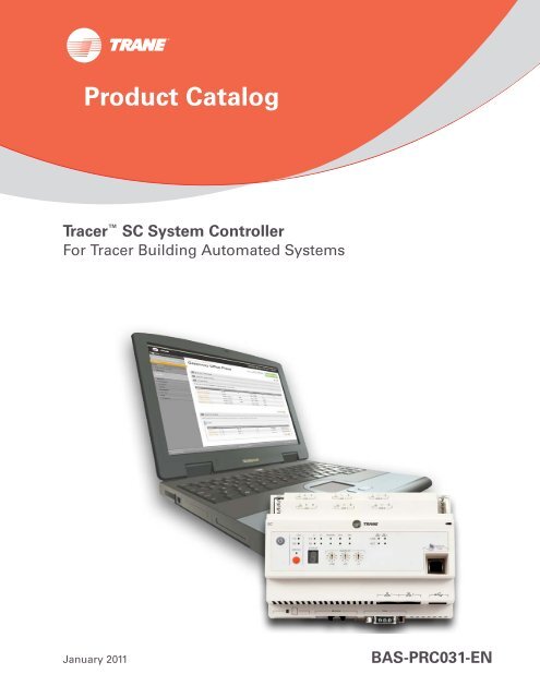
Product Catalog<br />
<strong>Tracer</strong> <strong>SC</strong> System Controller<br />
For <strong>Tracer</strong> Building Automated Systems<br />
January 2011<br />
BAS-PRC031-EN
Copyright<br />
© 2011 Trane All rights reserved<br />
This document and the information in it are the property of Trane and may not be used<br />
or reproduced in whole or in part, without the written permission of Trane. Trane reserves<br />
the right to revise this publication at any time and to make changes to its content without<br />
obligation to notify any person of such revision or change.<br />
Trademarks<br />
Trane and its logo are trademarks of Trane in the United States and other countries. All<br />
trademarks referenced in this document are the trademarks of their respective owners.<br />
2 BAS-PRC031-EN, 14 Jan 2011
Table of Contents<br />
Product Introduction . . . . . . . . . . . . . . . . . . . . . . . . . . . . . . . . . . . . . . . . . . . . . . . . . . . . 4<br />
User Interface . . . . . . . . . . . . . . . . . . . . . . . . . . . . . . . . . . . . . . . . . . . . . . . . . . . . . 5<br />
Alarms and Events . . . . . . . . . . . . . . . . . . . . . . . . . . . . . . . . . . . . . . . . . . . . 6<br />
Data Logs . . . . . . . . . . . . . . . . . . . . . . . . . . . . . . . . . . . . . . . . . . . . . . . . . . . . 6<br />
Schedules . . . . . . . . . . . . . . . . . . . . . . . . . . . . . . . . . . . . . . . . . . . . . . . . . . . . 7<br />
Area . . . . . . . . . . . . . . . . . . . . . . . . . . . . . . . . . . . . . . . . . . . . . . . . . . . . . . . . 8<br />
Variable Air Systems . . . . . . . . . . . . . . . . . . . . . . . . . . . . . . . . . . . . . . . . . . . 8<br />
Chilled Plant Control . . . . . . . . . . . . . . . . . . . . . . . . . . . . . . . . . . . . . . . . . . . 8<br />
Overrides . . . . . . . . . . . . . . . . . . . . . . . . . . . . . . . . . . . . . . . . . . . . . . . . . . . . 9<br />
Reports . . . . . . . . . . . . . . . . . . . . . . . . . . . . . . . . . . . . . . . . . . . . . . . . . . . . . . 9<br />
<strong>Tracer</strong> Graphical Programming (TGP2) . . . . . . . . . . . . . . . . . . . . . . . . . . . . 9<br />
Graphics and the <strong>Tracer</strong> Graphics Editor . . . . . . . . . . . . . . . . . . . . . . . . . . 9<br />
Tree Layout . . . . . . . . . . . . . . . . . . . . . . . . . . . . . . . . . . . . . . . . . . . . . . . . . 12<br />
Backup and Restore . . . . . . . . . . . . . . . . . . . . . . . . . . . . . . . . . . . . . . . . . . 12<br />
Troubleshooting . . . . . . . . . . . . . . . . . . . . . . . . . . . . . . . . . . . . . . . . . . . . . 12<br />
Security . . . . . . . . . . . . . . . . . . . . . . . . . . . . . . . . . . . . . . . . . . . . . . . . . . . . 12<br />
Hardware Components . . . . . . . . . . . . . . . . . . . . . . . . . . . . . . . . . . . . . . . . . . . . 13<br />
<strong>Tracer</strong> Building Automation System . . . . . . . . . . . . . . . . . . . . . . . . . . . . . . . . . . . . . 14<br />
<strong>Tracer</strong> System Architecture . . . . . . . . . . . . . . . . . . . . . . . . . . . . . . . . . . . . . . . . 14<br />
User Interface Control . . . . . . . . . . . . . . . . . . . . . . . . . . . . . . . . . . . . . . . . . 15<br />
System Control . . . . . . . . . . . . . . . . . . . . . . . . . . . . . . . . . . . . . . . . . . . . . . 15<br />
Unit Control . . . . . . . . . . . . . . . . . . . . . . . . . . . . . . . . . . . . . . . . . . . . . . . . . 15<br />
Service Tools . . . . . . . . . . . . . . . . . . . . . . . . . . . . . . . . . . . . . . . . . . . . . . . . . . . . . 16<br />
Resources . . . . . . . . . . . . . . . . . . . . . . . . . . . . . . . . . . . . . . . . . . . . . . . . . . . . . . . . . . . . 17<br />
Specifications . . . . . . . . . . . . . . . . . . . . . . . . . . . . . . . . . . . . . . . . . . . . . . . . . . . . . . . . . 18<br />
BAS-PRC031-EN, 14 Jan 2011 3
Product Introduction<br />
The <strong>Tracer</strong> <strong>SC</strong> system controller acts as the central coordinator for all individual equipment<br />
devices on a <strong>Tracer</strong> building automation system (see p. 14). The Web-based interface of the <strong>Tracer</strong><br />
<strong>SC</strong> system controller provides an easy and convenient way for building operators to access their<br />
building automation system. Access is available from any personal computer that meets system<br />
requirements, even from remote locations.<br />
The following list highlights the features and benefits of the <strong>Tracer</strong> <strong>SC</strong> system controller:<br />
Features<br />
User interface:<br />
•Web-enabled<br />
• Simpler to navigate to status and setting screens<br />
• View the most frequently needed facility status information<br />
from one page<br />
• Automatic data collection on key unit and system parameters<br />
• Enhanced data logging capabilities<br />
• Easier to create complex graphics to better represent your<br />
HVAC system<br />
Open, scalable, flexible controls:<br />
• Scalable system size to accommodate customers’ specific<br />
needs (small steps can be taken to building up system size)<br />
• Protocol-independent communications (BACnet, LonTalk)<br />
• BACnet, LonTalk, or any combination on the same system<br />
Achieve points toward Leadership in Energy and Environmental<br />
Design (LEED) certification through:<br />
• Site commissioning report<br />
• Energy data collection measurement<br />
• Optimizing energy performance<br />
• Maintaining indoor air quality<br />
Energy-saving programs:<br />
• Fan pressure optimization—Controls pressure in ductwork<br />
based on demand<br />
• Ventilation reset—Conditions only the required amount of<br />
outdoor air<br />
• Chiller Plant Control (CPC)—Manages chiller adds and subtracts to meet<br />
cooling loads<br />
Pre-programmed system applications:<br />
• Alarm and event log<br />
• Variable Air Systems (VAS)<br />
•Area<br />
• Chiller Plant Control<br />
•Scheduling<br />
• Overrides<br />
•Reporting<br />
• Data logging<br />
•Security<br />
Faster installation and commissioning:<br />
• Device discovery<br />
• Preformatted object types<br />
• Preconfiguration of controller data<br />
Benefits<br />
Provides access to system data from any PC in any location.<br />
More users can access the HVAC system.<br />
Increased usability and improved performance.<br />
Accommodates future changes through flexible technology.<br />
Lower operating costs through less energy use.<br />
Minimize impact on environment and infrastructure.<br />
Increase worker productivity through better air quality and<br />
reduced absenteeism.<br />
Make buildings run more efficiently.<br />
Provide consistent comfort and improved indoor air quality.<br />
Reduce/eliminate hot/cold complaints.<br />
Gets your building up and running faster.<br />
4 BAS-PRC031-EN, 14 Jan 2011
Product Introduction<br />
User Interface<br />
The <strong>Tracer</strong> <strong>SC</strong> user interface provides an easy way for building operators to set up, operate, and<br />
modify a building automation system. The home page (Figure 1) contains system status<br />
information and links to navigate to all areas of the system.<br />
The main features of the user interface are described in this section.<br />
Figure 1.<br />
<strong>Tracer</strong> <strong>SC</strong> user interface: Home page<br />
Tree layout<br />
tool for<br />
graphics<br />
Global<br />
navigation bar<br />
System<br />
navigation<br />
links<br />
Alarm quantity<br />
by event class<br />
Currently<br />
active<br />
schedules<br />
Current status<br />
BAS-PRC031-EN, 14 Jan 2011 5
Product Introduction<br />
Alarms and Events<br />
Events are occurrences that are detected by a <strong>Tracer</strong> building automation system. They can include<br />
diagnostics, critical operating conditions, as well as routine procedures.<br />
An event that is triggered by the detection of an abnormal or critical operating condition is<br />
generally considering to be an alarm. If an alarm exists, an alarm icon flashes in the global<br />
navigation bar, which remains visible in the right corner of every page of the user interface (see<br />
Figure 2, for example).<br />
When the system detects an event, data about the event appears in a log on the Alarms and Events<br />
page (Figure 2). The data displayed in the log includes when and where the event occurred and<br />
whether the operator is required to acknowledge it. An operator can also use the log to add<br />
comments about events. Column headings can be used to sort and filter events. They can also be<br />
removed or exported from the log.<br />
Figure 2.<br />
Alarms and Events log<br />
Data Logs<br />
The Alarms and Events log has seven categories that can be used to sort and filter them. Sorting<br />
can be based, for example, on severity level. Filtering can be used to view only the alarms from a<br />
specific piece of equipment, for example, or those received at a specific time or from a specific<br />
alarm category.<br />
Events can also be routed by e-mail to selected system operators. Event routing rules can be<br />
configured so that events respond to specific conditions when they occur.<br />
Data logs, also referred to as trends, allow the user to produce a variety of data samples at defined<br />
intervals to show the historical and current status of the facility. Data logs record, in real-time, the<br />
value of a data point in the system and the time at which the value was recorded.<br />
6 BAS-PRC031-EN, 14 Jan 2011
Product Introduction<br />
Data logs can be viewed in real-time, or at a later time in either graphical or tabular format. They<br />
can also be printed and saved. With the proper security access, system users can configure (create,<br />
delete, and update) and manage (clear, enable, and disable) data logs in the system. (See Figure 3<br />
for an example of a data log.)<br />
Figure 3.<br />
Data log example<br />
Schedules<br />
Scheduling is one of a facility’s most important energy-saving strategies. Its use ensures that<br />
equipment runs only when needed. Schedules can be used to:<br />
• Keep equipment running at minimal energy-use levels on weekends and holidays<br />
• Create exceptions to the standard schedule<br />
• Perform optimal start and stop of equipment to optimize energy use while maintaining comfort<br />
requirements<br />
• Change setpoints at specific times of day<br />
BAS-PRC031-EN, 14 Jan 2011 7
Product Introduction<br />
From the home page, you can select:<br />
• All schedules, which shows all schedules in the system<br />
• Active schedules, which shows just the active schedules in the system<br />
Figure 4 shows an example of an All Schedules page.<br />
Figure 4.<br />
The All Schedules page<br />
Area<br />
Variable Air Systems<br />
Chilled Plant Control<br />
The Area application coordinates HVAC equipment for a specific area of the building. You can use<br />
the application to assign unit controllers, binary outputs, and binary values to be members of a<br />
common area. You can then efficiently perform a single operation (such as changing a setpoint,<br />
creating a schedule, performing an override) and apply it to all members of the area. In addition,<br />
the area application can use one of six algorithms, along with area temperatures and humidity<br />
inputs, to make an economizing decision. The application also supports optimal start/stop,<br />
humidity pulldown, night purge, unoccupied heating/cooling, unoccupied humidify, unoccupied<br />
dehumidify, and timed override functions.<br />
The Variable Air Systems (VAS) application coordinates air-handling units, variable-air-volume<br />
(VAV) boxes, and ventilation within a building. VAV units are assigned to the air-handling unit that<br />
supplies air to them. The VAS application coordinates the start-up and shut-down of the system to<br />
ensure proper static pressure control. Energy-saving applications, including static pressure<br />
optimization and ventilation optimization, are available as standard VAS application features.<br />
The Chiller Plant Control application coordinates chillers and provides system chilled water control.<br />
It controls the leaving-water temperature by adding chillers as the building cooling load increases,<br />
calculates the chilled water setpoint for each chiller, and recovers from failures by starting the next<br />
chiller in the sequence immediately after a chiller is marked as failed.<br />
8 BAS-PRC031-EN, 14 Jan 2011
Product Introduction<br />
Overrides<br />
Reports<br />
CPC optimizes energy use by subtracting chillers when the requirements of the cooling load<br />
decreases. In addition, CPC matches chillers to the building load and equalizes runtime and wear<br />
on each chiller by using different rotation schemes.<br />
Overrides can be performed on equipment, areas, and points for either a designated amount of<br />
time or until the user decides to put the point back into automatic control.<br />
Standard reports for Trane equipment are available from <strong>Tracer</strong> <strong>SC</strong>. These reports provide a<br />
valuable source of data that can be used for record-keeping and troubleshooting.<br />
Report types include:<br />
• Site reports<br />
• VAS commissioning reports<br />
• Points reports<br />
• Chiller reports<br />
Report features include:<br />
• Scheduling reports to run during specific date periods and run frequencies<br />
• Specifying file storage options for scheduled reports<br />
• Exporting reports to save to your PC as csv, text, or pdf files<br />
• Editing scheduled reports<br />
<strong>Tracer</strong> Graphical Programming (TGP2)<br />
<strong>Tracer</strong> Graphical Programming (TGP2) is a powerful graphical program that allows you to<br />
customize <strong>Tracer</strong> system applications. TGP2 routines are typically used for sequencing equipment,<br />
calculating setpoints and values, and performing shutdown sequences.<br />
Note: TGP2 is available through the <strong>Tracer</strong> TU service tool.<br />
Graphics and the <strong>Tracer</strong> Graphics Editor<br />
The <strong>Tracer</strong> Graphics Editor, available through the <strong>Tracer</strong> TU service tool, is used to create, edit, and<br />
publish graphics for use on <strong>Tracer</strong> <strong>SC</strong>. Graphics on the <strong>Tracer</strong> <strong>SC</strong> are used to monitor and control<br />
building equipment and applications. They can display data related to climate, lighting, and other<br />
controllable operations. They can be used to change setpoints and to override equipment<br />
operation.<br />
The <strong>Tracer</strong> Graphics Editor can be used to align graphical elements, determine which elements<br />
appear on top, and perform cut, copy, and paste functions.<br />
You can include in graphics:<br />
• Any data that is available in the system as a numerical or text value<br />
• Analog values that can change colors if they deviate from a desired value<br />
• Multiple graphic images in JPEG, GIF, and animated GIF formats<br />
• Visual elements from the building, such as floor plans or exterior views from CAD drawings<br />
• Digital photography in JPG and GIF formats<br />
• Animated images to represent binary and analog values<br />
• Target buttons that provide links to related sources<br />
• User controls including push buttons, check boxes, drop-down list boxes, and entry fields<br />
Graphics can be grouped in a logical way to make navigation through the building automation<br />
system simulate walking through the building. See Figure 5, Figure 6, and Figure 7 as examples.<br />
BAS-PRC031-EN, 14 Jan 2011 9
Product Introduction<br />
Figure 5. Home page showing graphic of building exterior (Example 1)<br />
Figure 6. Home page with floor plan graphic (Example 2)<br />
10 BAS-PRC031-EN, 14 Jan 2011
Product Introduction<br />
Figure 7. Equipment status graphic (Example 3)<br />
BAS-PRC031-EN, 14 Jan 2011 11
Product Introduction<br />
Tree Layout<br />
The Tree Layout tool allows you to build a navigation tree in the user interface. A navigation tree<br />
provides an alternate way to navigate through the user interface. A navigation tree appears as a<br />
separate window on top of the page currently in view (see Figure 8).<br />
The navigation tree consists of nodes, display text, and icons. You build the tree by choosing<br />
display text for nodes, arranging the nodes, and assigning associated graphics to them. The<br />
graphics represent equipment and areas of the facility.<br />
Figure 8.<br />
Example of a navigation tree<br />
Backup and Restore<br />
Database changes made by other users are automatically reflected in the <strong>Tracer</strong> <strong>SC</strong> without the<br />
need for a central server. The system database can be archived or backed up for local or off-site<br />
storage of data if it is ever needed for restoring the system, in the event of a problem.<br />
Troubleshooting<br />
Security<br />
<strong>Tracer</strong> <strong>SC</strong> constantly evaluates all of the system parameters and reports abnormal conditions to<br />
the operator. Problems ranging from a communication failure caused by a broken wire to the failure<br />
of a sensor are automatically detected and reported to the Alarms and Events log (see p. 6).<br />
A sophisticated password system protects a <strong>Tracer</strong> system from unauthorized access. Each<br />
operator is assigned a role. Roles are defined by access rights. Several pre-defined roles can be<br />
selected from the <strong>Tracer</strong> <strong>SC</strong> interface. Operators have access only to those features which define<br />
their roles. Roles can also be customized. An operator with administrative-level security can access<br />
all information on the system and has the ability to alter passwords.<br />
12 BAS-PRC031-EN, 14 Jan 2011
Product Introduction<br />
Hardware Components<br />
The <strong>Tracer</strong> <strong>SC</strong> system controller is housed in a protective enclosure that makes it easy to access.<br />
Figure 9, p. 13, illustrates the parts and function of the device.<br />
Figure 9.<br />
<strong>Tracer</strong> <strong>SC</strong> system controller components<br />
LonTalk<br />
BACnet<br />
MS/TP LINK 1<br />
BACnet<br />
MS/TP LINK 2<br />
Intermodule<br />
connector<br />
(IMC) for<br />
power<br />
Intermodule<br />
connector<br />
(IMC) for<br />
power<br />
BACnet LEDs<br />
LonTalk LEDs<br />
Status LED<br />
Power button<br />
LonTalk service LED<br />
LonTalk service pin<br />
7-segment display<br />
Ethernet LEDs<br />
USB port for<br />
service tool<br />
connection<br />
Rotary switches<br />
USB host (future)<br />
SD card port (future)<br />
Modem (future; currently not enabled)<br />
RS-232 serial connection<br />
(factory use only)<br />
Ethernet network connection 2<br />
(supports TCP/IP) (recommended<br />
for direct connection to PC)<br />
Ethernet network connection 1<br />
(supports BACnet and TCP/IP<br />
(recommended for building<br />
LAN connection)<br />
BAS-PRC031-EN, 14 Jan 2011 13
<strong>Tracer</strong> Building Automation System<br />
A <strong>Tracer</strong> building automation system provides centralized building control through a single,<br />
integrated system. Climate, lighting, scheduling, energy consumption, air quality monitoring, and<br />
other controllable features of a facility can be programmed and managed by a <strong>Tracer</strong> building<br />
automation system for simple, consistent, and reliable operations.<br />
In addition to controlling any type of HVAC equipment, a <strong>Tracer</strong> building automation system can<br />
be connected to other building systems such as security systems and lab hood controls. These<br />
applications work together to maximize the comfort and security of people in the building, while<br />
minimizing energy use.<br />
<strong>Tracer</strong> System Architecture<br />
The control elements are distributed throughout the <strong>Tracer</strong> building automation system. system<br />
controller is at the highest level of control. Unitary equipment has unit controllers, which compose<br />
subsystems. All controllers on the system are integrated into a network for communication and<br />
monitoring.<br />
In a <strong>Tracer</strong> building automation system, control is distributed to the following three levels to ensure<br />
integrity, as shown in Figure 10, p. 14:<br />
• User interface control<br />
• System control<br />
• Unit control<br />
Figure 10. <strong>Tracer</strong> building automation system architecture<br />
LonTalk unit controllers<br />
(Complete list is on on p. 15)<br />
BACnet unit controllers<br />
(Complete list is on p. 15)<br />
Ethernet WAN/LAN (BACnet/IP)<br />
JENEsys BAS bridge<br />
<strong>Tracer</strong> <strong>SC</strong><br />
PC with Web browser<br />
14 BAS-PRC031-EN, 14 Jan 2011
<strong>Tracer</strong> Building Automation System<br />
User Interface Control<br />
System Control<br />
The <strong>Tracer</strong> <strong>SC</strong> user interface is viewed and operated from a Web-enabled PC. The user interface<br />
provides the ability for a building operator to configure, monitor, and modify system operations<br />
at the highest level of control (see “User Interface,” p. 5, for details.)<br />
Commands communicated from this control level can override automatic system-level control<br />
functions and some unit-level control functions.<br />
The <strong>Tracer</strong> <strong>SC</strong> system controller communicates with all unit controllers, acting as the central<br />
coordinator for all individual equipment devices. It gathers data from unit controllers, schedules<br />
and coordinates equipment operations, monitors for abnormal situations, and performs other<br />
miscellaneous building management and system-level functions.<br />
The <strong>Tracer</strong> <strong>SC</strong> system controller is designed to function automatically, without intervention of<br />
commands from the operator interface control level.<br />
The <strong>Tracer</strong> <strong>SC</strong> supports the JENEsys BAS bridge, which enhances system integration by<br />
providing a communication bridge between competitive proprietary protocols or other protocols<br />
such as Modbus.<br />
Unit Control<br />
Unit controllers provide all necessary unit control functions. They operate associated unitary<br />
equipment, while ensuring that all built-in safety features are enabled and that diagnostics are<br />
issued.<br />
Each controller is designed to operate in stand-alone mode. Therefore, if system control fails, unit<br />
operation can continue.<br />
Each <strong>Tracer</strong> <strong>SC</strong> can support a maximum quantity of 120 unit controllers. Unit controllers installed<br />
on a <strong>Tracer</strong> <strong>SC</strong> can be a combination of the following BACnet and LonTalk unit controllers.<br />
Notes:<br />
• Three types of product licenses are available for the <strong>Tracer</strong> <strong>SC</strong>. They are based on the maximum<br />
number of unit controllers that each <strong>Tracer</strong> <strong>SC</strong> supports: 30, 60, or 120.<br />
• BACnet controllers cannot exceed 60 controllers per link or 120 total controllers per <strong>Tracer</strong> <strong>SC</strong>.<br />
• Of the total number of unit controllers on the LonTalk link, the number of MP580/581s cannot<br />
exceed 20.<br />
BACnet (MS/TP) unit controllers supported by <strong>Tracer</strong> <strong>SC</strong><br />
<strong>Tracer</strong> <strong>SC</strong> systems support the following BACnet (MS/TP) unit controllers:<br />
• <strong>Tracer</strong> UC400 unit controller for variable-air-volume (VAV) equipment<br />
• <strong>Tracer</strong> UC400 unit controller for programmable equipment<br />
• <strong>Tracer</strong> UC800/AdaptiView unit controller for CenTraVac chillers<br />
• BCI-I: BACnet communications interface for IntelliPak system<br />
• BCI-C: BACnet communications interface for chillers<br />
• BCI-R: BACnet communications interface for ReliaTel<br />
• Non-Trane BACnet (MS/TP) devices<br />
LonTalk unit controllers supported by <strong>Tracer</strong> <strong>SC</strong><br />
<strong>Tracer</strong> <strong>SC</strong> systems support the following Trane unit controllers:<br />
• <strong>Tracer</strong> AH540/541 air-handler controller<br />
BAS-PRC031-EN, 14 Jan 2011 15
<strong>Tracer</strong> Building Automation System<br />
Service Tools<br />
• <strong>Tracer</strong> MP501 multi-purpose controller<br />
• <strong>Tracer</strong> MP503 input/output module<br />
• <strong>Tracer</strong> MP580/581 programmable controller<br />
• <strong>Tracer</strong> VV550/551 VAV controller<br />
• <strong>Tracer</strong> ZN510/511 zone controller<br />
• <strong>Tracer</strong> ZN517 unit controller<br />
• <strong>Tracer</strong> ZN520/521 zone controller<br />
• <strong>Tracer</strong> ZN523 zone controller<br />
• <strong>Tracer</strong> ZN524 water-source heat pump unit controller<br />
• <strong>Tracer</strong> ZN525 zone controller<br />
• <strong>Tracer</strong> CH530 chiller controller<br />
• <strong>Tracer</strong> CH532 chiller controller<br />
• LCI-C: LonTalk communications interface for chillers<br />
• LCI-I: LonTalk communications interface for IntelliPak systems<br />
• LCI-R: LonTalk communications interface for ReliaTel systems<br />
• Non-Trane LonTalk devices using <strong>SC</strong>C, DAC, and chiller profiles; and devices supporting<br />
LonTalk standard network generic variables<br />
Two service tools are available for the support of unit controllers and for additional functions on<br />
systems using <strong>Tracer</strong> <strong>SC</strong>:<br />
The <strong>Tracer</strong> TU Service Tool<br />
Use the <strong>Tracer</strong> TU service tool:<br />
• For configuring BACnet unit controllers<br />
• For downloading <strong>Tracer</strong> <strong>SC</strong> software updates<br />
• For obtaining data file from <strong>Tracer</strong> <strong>SC</strong> for use in creating TGP2 programs, and for accessing the<br />
TGP2 editor<br />
• For accessing the <strong>Tracer</strong> Graphics Editor (TGE), which is used to copy graphics files to the <strong>Tracer</strong><br />
<strong>SC</strong> and to edit them.<br />
• As an additional way to backup and restore data to <strong>Tracer</strong> <strong>SC</strong><br />
The Rover Service Tool<br />
Use the Rover Version 7 service tool:<br />
• For configuring LonTalk unit controllers<br />
• For setting the <strong>Tracer</strong> <strong>SC</strong> LonTalk network address<br />
• To discover unit controller and the <strong>Tracer</strong> <strong>SC</strong><br />
16 BAS-PRC031-EN, 14 Jan 2011
Resources<br />
The following resources are available for managing <strong>Tracer</strong> building automation systems:<br />
<strong>Tracer</strong> <strong>SC</strong> Installation, setup, and operation<br />
• <strong>Tracer</strong> <strong>SC</strong> System Controller Installation and Setup Guide (BAS-SVX31)<br />
• <strong>Tracer</strong> <strong>SC</strong> online help<br />
• <strong>Tracer</strong> <strong>SC</strong> Installation Instructions (X39641100)<br />
• Unit Controller Wiring Guide for the <strong>Tracer</strong> <strong>SC</strong> System Controller (BAS-SVN03)<br />
Programming<br />
• <strong>Tracer</strong> Graphical Programming (TGP2) Editor<br />
• <strong>Tracer</strong> Graphical Programming (TGP2) Application Guide (BAS-APG008) and online help<br />
HVAC applications<br />
• <strong>Tracer</strong> <strong>SC</strong> Air Systems Application Guide (BAS-APG007)<br />
• <strong>Tracer</strong> <strong>SC</strong> Chiller Plant Control Application Guide (BAS-APG012)<br />
Service tools<br />
• <strong>Tracer</strong> TU—<strong>Tracer</strong> TU Service Tool Getting Started Guide (TTU-SVN01) and online help<br />
• Rover Version 7 Operation and Setup Guide (EMTX-SVX01) and online help<br />
Graphics support<br />
• Centralized Services<br />
• <strong>Tracer</strong> Graphics Editor (TGE): launches from within the <strong>Tracer</strong> TU service tool (with online help)<br />
• <strong>Tracer</strong> TU Service Tool Getting Started Guide (TTU-SVN01)<br />
Software updates<br />
• <strong>Tracer</strong> TU Service Tool Getting Started Guide (TTU-SVN01)<br />
Web sites<br />
• MyTraneControls.com: A free online Web site designed to assist <strong>Tracer</strong> building automation<br />
system owners and operators.<br />
<strong>Tracer</strong> BAS training courses<br />
• The Trane College of Building Automation offers a comprehensive portfolio of technical<br />
courses on the operation, installation, and programming of <strong>Tracer</strong> building automation<br />
systems. Refer to http://trane.com/Commercial/DNA/View.aspx?i=586.<br />
Service, maintenance, troubleshooting<br />
In addition to the resources listed above:<br />
• Trane Product Support<br />
• Warranty information<br />
BAS-PRC031-EN, 14 Jan 2011 17
Specifications<br />
This section contains specifications for <strong>Tracer</strong> <strong>SC</strong> system controllers and for <strong>Tracer</strong> building<br />
automation systems.<br />
Computer<br />
<strong>Tracer</strong> <strong>SC</strong> system<br />
controller<br />
Browser requirements<br />
Software requirements<br />
Power requirements<br />
Operating environment<br />
Storage environment<br />
Enclosure (optional)<br />
Weight<br />
Mounting<br />
UL listing<br />
FCC<br />
• Internet Explorer Version 7.0 or higher, or Mozilla Firefox Version 3.0 or higher<br />
• Java SE Runtime Environment (JRE) Version 5.0 (preferred: Version 6 Update 10 or<br />
higher)<br />
• Adobe Flash player<br />
• Internet Explorer Version 7.0 or higher or Mozilla Firefox Version 3.0 or higher<br />
• USB driver—For service tool connection and for direct access to <strong>Tracer</strong> <strong>SC</strong> Web pages<br />
• Nominal rating: 120/230 Vac; 50 or 60 Hz; 1 pH<br />
• Maximum current: 6.0 A at 120 Vac dedicated circuit breaker<br />
• Temperature: From –40°F to 122°F (–40°C to 50°C)<br />
• Relative humidity: From 10% to 90%, non-condensing<br />
• Temperature: From –40°F to 158°F (–40°C to 70°C)<br />
• Relative humidity: From 5% to 95%, non-condensing<br />
• NEMA-1<br />
• 14 lb (6.5 kg)<br />
• Wall-mounted with #10 (5 mm) screws and #10 wall anchors<br />
• Mounting surface must be able to support 60 lb (28 kg)<br />
• UL -916-PAZX—energy management<br />
• CUL -C22.2—signal devices—Canada<br />
• FCC part 15, Class A<br />
CE<br />
• Emissions<br />
• Immunity<br />
• Safety<br />
EN61326:1998 Class B<br />
EN61326:1998 Commercial<br />
EN61010-1:2001<br />
Processor<br />
PowerPC405 Core<br />
Memory<br />
• FLASH<br />
• SDRAM<br />
500 MB<br />
256 MB<br />
System<br />
Communication<br />
Battery<br />
BACnet<br />
LonTalk<br />
• No battery required. The clock is maintained for a minimum of three days by the super<br />
capacitor. All other programs are backed up by nonvolatile memory.<br />
<strong>Tracer</strong> building automation systems communicates with BACnet devices that support:<br />
• Communications based on the BACnet ASHRAE/ANSI 135 standard<br />
• ENV-1805-1/ENV-13321-1<br />
• 10BASE-T/100BASE-TX dedicated Ethernet (ISO/IEC 8802-3) or Transmission Control<br />
Protocol/Internet Protocol (TCP/IP) compatible network<br />
Note: Non-Trane BACnet devices will be supported in a 2010 product release.<br />
<strong>Tracer</strong> building automation systems communicates with LonTalk devices that support:<br />
• Communications based on the EIA-709.1 (LonTalk) standard<br />
• LonTalk standard network variable types (SNVTs)<br />
• FTT-10A or FT-X1 transceivers<br />
• Twisted-pair physical media (Level 4 wiring)<br />
Note: Limited support for non-Trane LonTalk devices will be implemented in the July 2009 product<br />
release.<br />
18 BAS-PRC031-EN, 14 Jan 2011
Specifications<br />
Dimensions for the <strong>Tracer</strong> <strong>SC</strong> Enclosure (optional)<br />
Ø1.13 in (28.6 mm) +<br />
Ø1.38 in (34.9 mm)<br />
KNOCKOUT<br />
Ø.88 in (22.2 mm)<br />
KNOCKOUT<br />
3.13 in<br />
(80 mm)<br />
14.75 in<br />
(373 mm)<br />
2.25 in<br />
(56 mm)<br />
16.5 in<br />
(418 mm)<br />
15 in<br />
(381 mm)<br />
5.5 in<br />
(140 mm)<br />
Ø1.13 in (28.6 mm) +<br />
Ø1.38 in (34.9 mm)<br />
KNOCKOUT<br />
13.25 in<br />
(337 mm)<br />
BAS-PRC031-EN, 14 Jan 2011 19
Minimum Clearances for the <strong>Tracer</strong> <strong>SC</strong> Enclosure (optional)<br />
12 in. (30 cm)<br />
36 in. (90 cm)<br />
24 in. (60 cm)<br />
12 in. (30 cm)<br />
12 in. (30 cm)<br />
50 in. (130 cm recommended)<br />
Trane optimizes the performance of homes and buildings around the world. A business of Ingersoll Rand, the<br />
leader in creating and sustaining safe, comfortable and energy efficient environments, Trane offers a broad<br />
portfolio of advanced controls and HVAC systems, comprehensive building services, and parts. For more<br />
information, visit www.Trane.com.<br />
Trane has a policy of continuous product and product data improvement and reserves the right to change design and specifications without notice.<br />
© 2011 Trane All rights reserved<br />
BAS-PRC031-EN, 14 Jan 2011<br />
Supersedes BAS-PRC031-EN (19 Jul 2010)