DIGITAL THERMOSTAT - Western Gauge and Instruments Ltd.
DIGITAL THERMOSTAT - Western Gauge and Instruments Ltd.
DIGITAL THERMOSTAT - Western Gauge and Instruments Ltd.

Create successful ePaper yourself
Turn your PDF publications into a flip-book with our unique Google optimized e-Paper software.
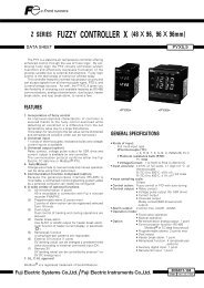
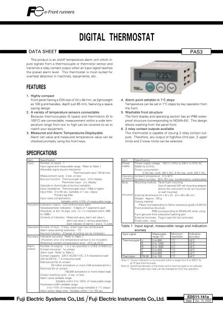
<strong>DIGITAL</strong> <strong>THERMOSTAT</strong><br />
DATA SHEET<br />
PAS3<br />
This product is an on/off temperature alarm unit which inputs<br />
signals from a thermocouple or thermistor sensor <strong>and</strong><br />
transmits a relay contact output when an input signal reaches<br />
the preset alarm level. This thermostat is most suited for<br />
overheat detection in machines, equipments, etc.<br />
FEATURES<br />
1. Highly compact<br />
Front panel having a DIN size of 24 x 48 mm, as lightweight<br />
as 100 g <strong>and</strong> besides, depth just 85 mm, featuring a space<br />
saving design.<br />
2. A variety of temperature sensors connectable<br />
Because thermocouples (5 types) <strong>and</strong> thermistors (0 to<br />
100°C) are connectable, measurement within a wide temperature<br />
range from low to high can be covered so as to<br />
match your equipment.<br />
3. Measured <strong>and</strong> Alarm Temperatures Displayable<br />
Alarm set value <strong>and</strong> measured temperature value can be<br />
checked promptly using the front keys.<br />
4. Alarm point settable in 1°C steps<br />
Temperature can be set in 1°C steps by key operation from<br />
the front.<br />
5. Washable front structure<br />
The front display <strong>and</strong> operating section has an IP66 waterproof<br />
structure (corresponding to NEMA-4X). This design<br />
allows washing from the panel front.<br />
6. 2 relay contact outputs available<br />
This thermostat is capable of issuing 2 relay contact outputs.<br />
Therefore, any output of high/low limit pair, 2 upper<br />
limits <strong>and</strong> 2 lower limits can be selected.<br />
SPECIFICATIONS<br />
Item Specification<br />
Input Number of inputs: 1<br />
Input signal <strong>and</strong> measurable range: Refer to Table 1.<br />
Allowable signal source resistance:<br />
Thermocouple input 100 Ω max.<br />
Measurement cycle: 2 sec. or less<br />
Burnout function: Thermocouple input; UUU display<br />
Thermistor input: LLL display<br />
(Upscale or downscale at burnout settable)<br />
Input impedance: Thermocouple input 1 MΩ or higher<br />
Input filter: 0 to 90 sec. (settable in 1 sec. steps)<br />
Primary lag filter<br />
Input value compensation:<br />
Settable within ±10% of measurable range<br />
Indication Indication means: LCD (without back light)<br />
Value/parameter indication: 4 digits of 7 segments each<br />
(However, at the 1st digit, only - or 1 is indicated within -999<br />
to 1999.)<br />
Contents of indication: Measured value, alarm set value 1,<br />
alarm set value 2, various parameters<br />
Each indicator of alarms 1 <strong>and</strong> 2, ˚C scale<br />
Operation Number of keys: 3 keys, sheet type keys (embossed)<br />
Alarm value setting resolution: 1˚C<br />
Key lock function: (Change of setting can be inhibited.)<br />
Accuracy Indication accuracy: Refer to Table 1.<br />
(However, error of a temperature sensor is not included.)<br />
Reference contact compensation error: ±3˚C (at 23˚C)<br />
Alarm Number of outputs: 1 or 2 (as specified in CODE SYMBOLS)<br />
output Contact structure: 1a contact<br />
Alarm type: Refer to Table 2.<br />
Contact capacity: 220 V AC/30 V DC, 2 A (resistance load)<br />
220 AC/30 DC, 1 A (inductive load)<br />
Mechanical life of contact:<br />
20 million activations or more (100 activations/min.)<br />
Electrical life of contact:<br />
100,000 activations or more (rated load)<br />
Output resetting cycle: 2 sec. or less<br />
Alarm value settable range:<br />
Settable within 0 to 100% of measurable range<br />
Hysteresis width settable range:<br />
0 to 110% of measurable range (settable in 1˚C steps)<br />
Alarm action delay time: Settable within 1 to 120 sec.<br />
Item Specification<br />
Power Power supply voltage: 100 V (–15%) to 240 V (+10%) AC<br />
supply 50/60 Hz (±10%)<br />
Power consumption:<br />
3 VA max. (with 100 V AC), 6 VA max. (with 240 V AC)<br />
Operating Ambient temperature: 0 to 50˚C<br />
conditions Ambient humidity: 90% RH max. (condensation unallowable)<br />
Body Mounting method: Panel flush mounting<br />
Use of optional DIN rail-mounting adapter<br />
allows the instrument to be rail mounted<br />
or wall mounted.<br />
structure External dimensions (H x W x D): 24 x 48 x 85 mm<br />
Weight: Approx. 100 g<br />
Casing material:<br />
Plastic (corresponding to flame resistance grade UL94V-0)<br />
Front protective structure:<br />
IP66 (corresponding to NEMA-4X) when using<br />
Fuji’s genuine front waterproof packing part<br />
External terminals: Plug-in type (for bar terminals)<br />
Finish color: Ivory<br />
Table 1 Input signal, measurable range <strong>and</strong> indication<br />
acurasy<br />
Input signal<br />
Thermocouple<br />
Thermistor<br />
J<br />
K<br />
R<br />
T<br />
E<br />
PB-36<br />
Measurable<br />
range (˚C)<br />
0 to 800<br />
0 to 1200<br />
0 to 1600<br />
0 to 400<br />
0 to 600<br />
0 to 100<br />
Minimum<br />
resolution<br />
1˚C<br />
1˚C<br />
4˚C<br />
1˚C<br />
1˚C<br />
1˚C<br />
Indication<br />
accuracy<br />
±3˚C<br />
±3˚C<br />
±4˚C<br />
±3˚C<br />
±3˚C<br />
±4˚C<br />
Note 1) Correct indication is not ensured within a range from 0 to 500˚C for<br />
an R type thermocouple.<br />
Note 2) Switching between a thermistor <strong>and</strong> a thermocouple is not allowed.<br />
Thermocouple input type can be changed by front key operation.<br />
EDS11-141a<br />
Date Apr. 10, 2002
PAS3<br />
Table 2 Alarm types<br />
Code of<br />
PA1, 2<br />
0<br />
1<br />
Alarm<br />
direction<br />
No<br />
alarm<br />
Upper<br />
limit<br />
Set value<br />
notation<br />
–<br />
Absolute<br />
value<br />
With<br />
holding<br />
(Note 2)<br />
–<br />
No<br />
Relay<br />
action<br />
at alarm<br />
–<br />
Relay<br />
excitation<br />
Action diagram<br />
(Note 1)<br />
CODE SYMBOLS<br />
Input signal<br />
Thermocouple<br />
Thermistor<br />
Temperature sensor<br />
Option<br />
Provided<br />
Number of alarm<br />
1<br />
2<br />
1<br />
2<br />
Code symbols<br />
PAS3K1Y1<br />
PAS3K1A1<br />
PAS3H1Y1<br />
PAS3H1A1<br />
2<br />
3<br />
4<br />
5<br />
6<br />
7<br />
8<br />
Lower<br />
limit<br />
Upper<br />
limit<br />
Lower<br />
limit<br />
Upper<br />
limit<br />
Lower<br />
limit<br />
Upper<br />
limit<br />
Lower<br />
limit<br />
Absolute<br />
value<br />
Absolute<br />
value<br />
Absolute<br />
value<br />
Absolute<br />
value<br />
Absolute<br />
value<br />
Absolute<br />
value<br />
Absolute<br />
value<br />
No<br />
Yes<br />
Yes<br />
No<br />
No<br />
Yes<br />
Yes<br />
Relay<br />
excitation<br />
Relay<br />
excitation<br />
Relay<br />
excitation<br />
Relay nonexcitation<br />
Relay nonexcitation<br />
Relay nonexcitation<br />
Relay nonexcitation<br />
(Note 1) How to read action<br />
area: A range in which “ALM1 or ALM2” is indicated on LCD at the front.<br />
area: A range in which alarm relay is excited<br />
point: Alarm set value<br />
The horizontal axis represents measured values (PV).<br />
(Note 2) What is the hold function?<br />
Even if the process value is within the alarm range when turning on power,<br />
the alarm does not turn on immediately but only after it leaves <strong>and</strong> then returns<br />
to the alarm range.<br />
PV (process value)<br />
OPTIONAL DEVICE<br />
DIN rail adapter (Model: ZZP*CTK368715P1)<br />
SETTING at DELIVERY<br />
Measurable range K thermocouple input (0 to 1200˚C)<br />
Thermistor input (0 to 100˚C)<br />
Alarm set value<br />
K thermocouple input: For 1-point alarm<br />
(upper limit 1200˚C)<br />
K thermocouple input: For 2-point alarm<br />
(upper limit 1200˚C, lower limit alarm 0˚C)<br />
Thermistor input: For 1-point alarm<br />
(upper limit 100˚C)<br />
Thermistor input: For 2-point alarm<br />
(upper limit 100˚C, lower limit alarm 0˚C)<br />
Alarm hysteresis width 1˚C<br />
Alarm delay time<br />
0 sec.<br />
Indication<br />
Measured value<br />
Burnout<br />
Upscale at burnout<br />
Input filter<br />
5 sec.<br />
Input value compensation 0%<br />
Note 1) Switching between a thermistor <strong>and</strong> a thermocouple is not allowed.<br />
Note 2) Thermocouple input type can be changed by front key operation.<br />
Power ON<br />
Lower limit alarm<br />
Lower limit alarm<br />
(with hold)<br />
Power OFF<br />
off<br />
off<br />
on<br />
Power ON<br />
Fig. 1 Alarm output hysteresis width<br />
off<br />
on<br />
on<br />
off<br />
off<br />
Period where lower<br />
limit alarm is output<br />
SCOPE of DELIVERY<br />
Thermostat unit, panel-mounting adapter, front waterproof<br />
packing, instruction manual<br />
Thermistor sensor added for thermistor input<br />
Alarm output<br />
Alarm output hysteresis width (˚C)<br />
(1˚C)<br />
Example 49˚C Set value 50˚C<br />
ON<br />
Example) Alarm set value 50˚C<br />
Alarm output hysteresis width 1˚C<br />
ATTACHED THERMISTOR SENSOR<br />
• Attachment for thermistor-input thermostat<br />
Measurable range<br />
0 to 100˚C<br />
B constant<br />
3390 K<br />
Nominal resistance value<br />
6 kΩ (0˚C)<br />
Lead wire<br />
Heat-resisting vinyl chloride wire<br />
Lead wire length<br />
500 mm<br />
Lead wire heat resisting temperature –20 to 105˚C<br />
Color code<br />
Black<br />
Accuracy<br />
Within ±2˚C<br />
• Outline diagram (unit: mm)<br />
φ 6.5 MAX.<br />
Epoxy resins<br />
(black)<br />
20 MAX.<br />
Heat-resisting parallel vinyl chloride wire<br />
(12/0.18 TA)(black)<br />
About 520<br />
5<br />
CODE SYMBOLS of SPARE THERMISTOR<br />
SENSOR<br />
ZZP*CTK7L3491P1
OUTLINE DIAGRAM (Unit:mm)<br />
Waterproof packing<br />
48<br />
1<br />
PV SET1 SET2<br />
24<br />
ALM1 ALM2<br />
34.2<br />
22<br />
4<br />
84<br />
85<br />
Mounting adapter<br />
Panel (1 ≤ t ≤ 8)<br />
PANEL CUTOUT DIAGRAM (Unit:mm)<br />
For mounting “n” units<br />
For close mounting in horizontal direction<br />
45.0 +0.5<br />
0<br />
(48 X n–3)<br />
+0.5<br />
0<br />
22.2<br />
+0.3<br />
0<br />
50 MIN.<br />
22.2 +0.3<br />
0<br />
This mounting does not meet NEMA-4X/IP66<br />
(front waterproof specification).<br />
(Because the packing cannot be used in horizontally<br />
close mounting.)<br />
57 MIN.<br />
DIN RAIL ADAPTER<br />
52.4<br />
PV SET1 SET2<br />
45.4<br />
ALM1 ALM2<br />
2-ø4.3<br />
DIN rail<br />
DIN rail adapter (option)<br />
For wall mounting<br />
43.8<br />
96.2<br />
92.5<br />
M4<br />
PAS3...<br />
MFD.<br />
No.<br />
36.8<br />
9<br />
MAX. torque 0.49Nm
PAS3<br />
CONNECTION DIAGRAM<br />
USABLE WIRING MATERIALS<br />
• Wire<br />
<strong>Gauge</strong>: AWG28 (0.1 mm 2 ) ... AWG16 (1.25 mm 2 )<br />
Strip-off length: 5 to 6 mm<br />
AWG28...AWG16<br />
1 2 3<br />
– +<br />
Thermocouple<br />
input<br />
2 3<br />
4 5 6 7 8 9<br />
Alarm output 1<br />
Alarm output 2<br />
Power supply<br />
AC 100-240 V<br />
50/60 Hz<br />
5 to 6 mm<br />
• Bar terminal<br />
Dimension of strip-off conductor section: 2 x 1.5 mm or smaller<br />
Length of strip-off conductor section: 5 to 6 mm<br />
1.5MAX.<br />
2MAX.<br />
5 to 6 mm<br />
Thermistor<br />
CONNECTION METHOD<br />
PAS3<br />
Screw driver<br />
Wires<br />
Caution on Safety<br />
*Before using this product, be sure to read its instruction manual in advance.<br />
Head office<br />
6-17, Sanbancho, Chiyoda-ku, Tokyo 102-0075, Japan<br />
http://www.fesys.co.jp<br />
Sales Div.<br />
International Sales Dept.<br />
No.1, Fuji-machi, Hino-city, Tokyo, 191-8502 Japan<br />
Phone: 81-42-585-6201, 6202<br />
Fax: 81-42-585-6187<br />
http: //www.fic-net.co.jp<br />
Information in this catalog is subject to change without notice.<br />
Printed in Japan