DIGITAL THERMOSTAT - Western Gauge and Instruments Ltd.
DIGITAL THERMOSTAT - Western Gauge and Instruments Ltd.
DIGITAL THERMOSTAT - Western Gauge and Instruments Ltd.

Create successful ePaper yourself
Turn your PDF publications into a flip-book with our unique Google optimized e-Paper software.
PAS3<br />
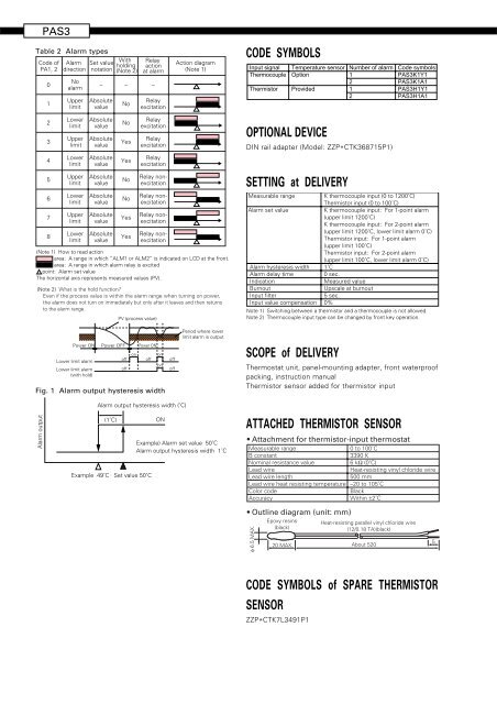
Table 2 Alarm types<br />
Code of<br />
PA1, 2<br />
0<br />
1<br />
Alarm<br />
direction<br />
No<br />
alarm<br />
Upper<br />
limit<br />
Set value<br />
notation<br />
–<br />
Absolute<br />
value<br />
With<br />
holding<br />
(Note 2)<br />
–<br />
No<br />
Relay<br />
action<br />
at alarm<br />
–<br />
Relay<br />
excitation<br />
Action diagram<br />
(Note 1)<br />
CODE SYMBOLS<br />
Input signal<br />
Thermocouple<br />
Thermistor<br />
Temperature sensor<br />
Option<br />
Provided<br />
Number of alarm<br />
1<br />
2<br />
1<br />
2<br />
Code symbols<br />
PAS3K1Y1<br />
PAS3K1A1<br />
PAS3H1Y1<br />
PAS3H1A1<br />
2<br />
3<br />
4<br />
5<br />
6<br />
7<br />
8<br />
Lower<br />
limit<br />
Upper<br />
limit<br />
Lower<br />
limit<br />
Upper<br />
limit<br />
Lower<br />
limit<br />
Upper<br />
limit<br />
Lower<br />
limit<br />
Absolute<br />
value<br />
Absolute<br />
value<br />
Absolute<br />
value<br />
Absolute<br />
value<br />
Absolute<br />
value<br />
Absolute<br />
value<br />
Absolute<br />
value<br />
No<br />
Yes<br />
Yes<br />
No<br />
No<br />
Yes<br />
Yes<br />
Relay<br />
excitation<br />
Relay<br />
excitation<br />
Relay<br />
excitation<br />
Relay nonexcitation<br />
Relay nonexcitation<br />
Relay nonexcitation<br />
Relay nonexcitation<br />
(Note 1) How to read action<br />
area: A range in which “ALM1 or ALM2” is indicated on LCD at the front.<br />
area: A range in which alarm relay is excited<br />
point: Alarm set value<br />
The horizontal axis represents measured values (PV).<br />
(Note 2) What is the hold function?<br />
Even if the process value is within the alarm range when turning on power,<br />
the alarm does not turn on immediately but only after it leaves <strong>and</strong> then returns<br />
to the alarm range.<br />
PV (process value)<br />
OPTIONAL DEVICE<br />
DIN rail adapter (Model: ZZP*CTK368715P1)<br />
SETTING at DELIVERY<br />
Measurable range K thermocouple input (0 to 1200˚C)<br />
Thermistor input (0 to 100˚C)<br />
Alarm set value<br />
K thermocouple input: For 1-point alarm<br />
(upper limit 1200˚C)<br />
K thermocouple input: For 2-point alarm<br />
(upper limit 1200˚C, lower limit alarm 0˚C)<br />
Thermistor input: For 1-point alarm<br />
(upper limit 100˚C)<br />
Thermistor input: For 2-point alarm<br />
(upper limit 100˚C, lower limit alarm 0˚C)<br />
Alarm hysteresis width 1˚C<br />
Alarm delay time<br />
0 sec.<br />
Indication<br />
Measured value<br />
Burnout<br />
Upscale at burnout<br />
Input filter<br />
5 sec.<br />
Input value compensation 0%<br />
Note 1) Switching between a thermistor <strong>and</strong> a thermocouple is not allowed.<br />
Note 2) Thermocouple input type can be changed by front key operation.<br />
Power ON<br />
Lower limit alarm<br />
Lower limit alarm<br />
(with hold)<br />
Power OFF<br />
off<br />
off<br />
on<br />
Power ON<br />
Fig. 1 Alarm output hysteresis width<br />
off<br />
on<br />
on<br />
off<br />
off<br />
Period where lower<br />
limit alarm is output<br />
SCOPE of DELIVERY<br />
Thermostat unit, panel-mounting adapter, front waterproof<br />
packing, instruction manual<br />
Thermistor sensor added for thermistor input<br />
Alarm output<br />
Alarm output hysteresis width (˚C)<br />
(1˚C)<br />
Example 49˚C Set value 50˚C<br />
ON<br />
Example) Alarm set value 50˚C<br />
Alarm output hysteresis width 1˚C<br />
ATTACHED THERMISTOR SENSOR<br />
• Attachment for thermistor-input thermostat<br />
Measurable range<br />
0 to 100˚C<br />
B constant<br />
3390 K<br />
Nominal resistance value<br />
6 kΩ (0˚C)<br />
Lead wire<br />
Heat-resisting vinyl chloride wire<br />
Lead wire length<br />
500 mm<br />
Lead wire heat resisting temperature –20 to 105˚C<br />
Color code<br />
Black<br />
Accuracy<br />
Within ±2˚C<br />
• Outline diagram (unit: mm)<br />
φ 6.5 MAX.<br />
Epoxy resins<br />
(black)<br />
20 MAX.<br />
Heat-resisting parallel vinyl chloride wire<br />
(12/0.18 TA)(black)<br />
About 520<br />
5<br />
CODE SYMBOLS of SPARE THERMISTOR<br />
SENSOR<br />
ZZP*CTK7L3491P1