Z SERIES FUZZY CONTROLLER X (48)96, 96)96mm)
Z SERIES FUZZY CONTROLLER X (48)96, 96)96mm)
Z SERIES FUZZY CONTROLLER X (48)96, 96)96mm)

You also want an ePaper? Increase the reach of your titles
YUMPU automatically turns print PDFs into web optimized ePapers that Google loves.
Z <strong>SERIES</strong> <strong>FUZZY</strong> <strong>CONTROLLER</strong> X (<strong>48</strong>)<strong>96</strong>, <strong>96</strong>)<strong>96</strong>mm)<br />
DATA SHEET<br />
PYX5,9<br />
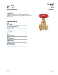
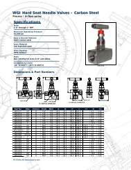
The PYX is a state-the-art temperature controller offering<br />
enhanced control through the use of fuzzy logic. By employing<br />
fuzzy logic the PYX virtually eliminates system<br />
overshoot and effectively supresses fluctuation of the<br />
process variable due to external disturbances. Fuzzy logic<br />
control is the technology of tomorrow offered today.<br />
This controller features universal input/output circuitry and<br />
can accept signals from all thermocouple types, RTD's, and<br />
current/voltage sources. As well, the PYX-5, 9 gives you<br />
the flexibility of choosing such available features as RS-<strong>48</strong>5<br />
communications, analog retransmission, dual output, heater<br />
break alarm, and loop break alarm, to name a few.<br />
FEATURES<br />
1. Incorporation of fuzzy control<br />
An improved response characteristic of controller is<br />
ensured thanks to the fuzzy control exercised while<br />
detecting an overshoot or a difference from the set<br />
temperature value due to a large disturbance.<br />
(Time taken for returning to the set value can be shortened<br />
and temperature variation width can be narrowed.)<br />
2. Universal input<br />
11 kinds of thermocouples, resistance bulbs and voltage/<br />
current inputs is available.<br />
3. Universal output (option)<br />
Relay contact, voltage pulse output for SSR drive and<br />
current output is available on one controller.<br />
The communication protocol conforms either the Fuji<br />
Electric CC data line or Modbus® RTU.<br />
4. Auto/Manual<br />
Change auto-mode to manual-mode and manual operation<br />
can be done using front panel keys.<br />
5. Communication function comprised (option)<br />
Because the general-purpose interface (RS-<strong>48</strong>5) is<br />
mountable, a centralized monitoring/setting system aided<br />
by a personal computer can readily be configured.<br />
6. A wide variety of optional functions<br />
(1) A0 re-transmission (1 point)<br />
A0 is recordable in connection with Fuji's microjet<br />
recorder PHA/PHC.<br />
(2) Programmable alarm (2 points max.)<br />
2 points of alarm action can be registered selected<br />
from 16 kinds.<br />
(3) Dual output<br />
Dual control of heating and cooling operations are<br />
allowed.<br />
(4) Heater break alarm<br />
Use ALM1 or ALM2 output for heater break alarm.<br />
(with function of heater current display, in parameter<br />
" ")<br />
(5) Ramp/soak function<br />
4 ramp/soak-pair patterns are registrable.<br />
(6) External DI function (1 point)<br />
SV (setting value) can be changed a predetermined<br />
value according to external command input (DI).<br />
(7) Remote SV<br />
SV (setting value) can be controlled by external 1 to<br />
5V DC analog input.<br />
7. UL, C-UL approval<br />
Modbus ® is a registered trademark of Gould Modicon.<br />
<br />
GENERAL SPECIFICATIONS<br />
<br />
• Kinds of input:<br />
Full multi-input type<br />
•Thermocouple (TC):<br />
J, K, R, B, T, E, S, N, U, WRe5-26, PL-II<br />
• Platinum resistance bulb (RTD):<br />
Pt 100Ω<br />
• Voltage/Current: 1 to 5V/0 to 5V/4 to 20mA DC<br />
• Input accuracy: ± 0.5% of full scale, ± 1 digit (± 1°C at<br />
thermocouple)<br />
B (TC) 0 to 500°C: ±5% of<br />
R (TC) 0 to 400°C: ±1% of } full scale<br />
• Input sampling cycle:<br />
0.5sec<br />
• Control action: Fuzzy control or PID with auto-tuning<br />
• Control output: • Relay contact<br />
• Voltage pulse output (for SSR drive)<br />
• Current output<br />
• Universal output<br />
(Relay contact/SSR drive/current<br />
output)<br />
• Alarm output: 2 points max. (ALM1, ALM2)<br />
• Operation mode:<br />
• Fixed value operation<br />
• Manual operation<br />
• Option • Re-transmission analog output: 1 point<br />
• Communication function: RS-<strong>48</strong>5<br />
Modbus® or CC-data line protocol.<br />
• Programmable alarms: 2 points max.<br />
• Dual output<br />
• Heater break alarm: 1 point<br />
• Ramp/soak function: 4 ramp/soak-pair<br />
patterns<br />
• Auxiliary digital input: 1 point<br />
• Remote SV input: 1 point<br />
EDSX11-134<br />
Date Jan. 25, 1999
PYX5,9<br />
2<br />
FUNCTION AND PERFORMANCE<br />
1. Input<br />
(1) Process variable input signal<br />
Kind of input<br />
Thermocouple<br />
Resistance<br />
bulb<br />
Voltage input<br />
Current input<br />
Description<br />
• Cold junction compensation<br />
comprised<br />
• Burn-out circuit built in<br />
• Burn-out circuit built in<br />
• Allowable wiring resistance<br />
10Ω max. (per wire)<br />
Input resistance 1MΩ min.<br />
Input resistance 250Ω<br />
Remarks: (1) For 4 to 20mA DC input specification, a 250 Ω resistor is<br />
furnished with the controller delivered.<br />
(2) The 250Ω resistor should be removed for changeover from<br />
4 to 20mA DC to 1 to 5V DC input.<br />
Kinds of input<br />
Resistance<br />
bulb<br />
JIS<br />
IEC<br />
J<br />
K<br />
R<br />
B<br />
T<br />
E<br />
S<br />
N (Nichrosil-Nisil)<br />
U<br />
WRe5-26(Tangsten rhenium)<br />
PL-II (Platinel)<br />
Pt 100<br />
1 to 5V DC<br />
0 to 5V DC<br />
4 to 20mA DC<br />
(a) Input accuracy:± 0.5% of full scale, ± 1 digit<br />
Cold junction compensation error:<br />
± 1°C<br />
(b) Input range<br />
Pt100<br />
Thermocouple<br />
J<br />
J<br />
K<br />
K<br />
K<br />
R<br />
B<br />
T<br />
T<br />
E<br />
E<br />
S<br />
N<br />
U<br />
WRe5-26<br />
PL-II<br />
Voltage 1 to 5V DC<br />
0 to 5V DC<br />
Current 4 to 20mA<br />
DC<br />
Code<br />
00<br />
01<br />
02<br />
03<br />
04<br />
05<br />
06<br />
07<br />
20<br />
21<br />
22<br />
23<br />
24<br />
25<br />
26<br />
27<br />
28<br />
29<br />
2A<br />
2B<br />
2C<br />
2D<br />
2E<br />
2F<br />
40<br />
41<br />
40*<br />
Temperature<br />
range [°C]<br />
0 to 150<br />
0 to 300<br />
0 to 500<br />
0 to 600<br />
–50 to 100<br />
–100 to 200<br />
–150 to 600<br />
–150 to 850<br />
0 to 400<br />
0 to 800<br />
0 to 400<br />
0 to 800<br />
0 to 1200<br />
0 to 1600<br />
0 to 1800<br />
–199.9 to 200<br />
–150 to 400<br />
0 to 800<br />
–199.9 to 800<br />
0 to 1600<br />
0 to 1300<br />
–199.9 to 400<br />
0 to 2300<br />
Temperature<br />
range [°F]<br />
32 to 302<br />
32 to 572<br />
32 to 932<br />
32 to 1112<br />
–58 to 212<br />
–1<strong>48</strong> to 392<br />
–238 to 1112<br />
–238 to 1562<br />
32 to 752<br />
32 to 1472<br />
32 to 752<br />
32 to 1472<br />
32 to 2192<br />
32 to 2912<br />
32 to 3272<br />
–328 to 392<br />
–238 to 752<br />
32 to 1472<br />
–328 to 1472<br />
32 to 2912<br />
32 to 2372<br />
–328 to 752<br />
32 to 4172<br />
32 to 2372<br />
0 to 1300<br />
Scale settable within<br />
–1999 to 9999<br />
(<br />
* ) Connect 250Ω between terminal<br />
No. 16 and 18 in case of current input<br />
0.1°C 0.1°F<br />
display<br />
<br />
<br />
<br />
×<br />
<br />
<br />
<br />
<br />
<br />
<br />
<br />
<br />
<br />
<br />
<br />
<br />
<br />
×<br />
×<br />
×<br />
<br />
<br />
<br />
<br />
×<br />
×<br />
(c) Input sampling cycle: 500ms<br />
(d) Burn-out<br />
• Control output direction (upper side or lower side) is programmable<br />
at occurrence of burn-out.<br />
• For resistance bulb input, detection is allowed even if<br />
any of the three wires is discontinued.<br />
(2) Digital input (option)<br />
Number of input points: 1 point<br />
Spec.<br />
: 16V DC, 15mA<br />
(3) Remote SV input (option)<br />
Input signal: 1 to 5V DC, 1 point<br />
Accuracy: ± 0.5% ± 1 digit<br />
Input sampling cycle: 0.5sec<br />
Input scaling: Allowed<br />
Input filter: First delay (time constant 1sec fixed)<br />
Display of remote mode: LED on front panel<br />
Detection of input signal wire discontinued: None<br />
<br />
×<br />
×<br />
<br />
×<br />
×<br />
<br />
×<br />
<br />
×<br />
×<br />
×<br />
×<br />
×<br />
×<br />
×<br />
×<br />
×<br />
×<br />
×<br />
×<br />
×<br />
Changeover Remote/Auto: Bumpless<br />
2. Control functions<br />
(1) Fuzzy control:The basic actions in PID control have been<br />
realized according to fuzzy control rules.<br />
(2) PID control with auto-tuning:<br />
Proportional band (P): 0 to 999.9%<br />
(2-position action when P = 0)<br />
Reset time (I): 0 to 3200sec<br />
(Integral action cut when I = 0)<br />
Rate time (D): 0 to 999.9sec<br />
(Derivation action cut when D = 0)<br />
(Fuzzy control action or PID action with auto-tuning is<br />
selectable by using the front panel key.)<br />
(3) Proportional cycle: 1 to 120sec<br />
(4) Control cycle: 500ms<br />
3. Output<br />
(1) Control output<br />
– Standard type – (option)<br />
Of the following output types, any one should be<br />
specified.<br />
Relay contact<br />
output<br />
SSR drive<br />
output<br />
Normally open<br />
SPDT contact<br />
Transistor<br />
output<br />
Electrical expected life :<br />
More than 10 5 operations at<br />
220V AC, 3A (resistive load)<br />
Mechanical expected life :<br />
More than 2 x 10 7 operations<br />
ON: 9 to 24V DC, 20mA max.<br />
OFF: 0.5V or less<br />
Load resistance: 600Ω or more<br />
Current output 4 to 20mA DC Allowable load resistance :<br />
600Ω or less<br />
– Dual output type – (option)<br />
Of the following output types, any one should be specified<br />
for each of the heating and cooling sides.<br />
Relay contact<br />
output<br />
SSR drive<br />
output<br />
Normally open<br />
SPDT contact<br />
Transistor<br />
output<br />
Electrical expected life :<br />
More than 10 5 operations at<br />
220V AC, 3A (resistive load)<br />
Mechanical expected life :<br />
More than 2 x 10 7 operations<br />
ON: 9 to 24V DC, 20mA max.<br />
OFF: 0.5V or less<br />
Load resistance: 600Ω or more<br />
Current output 4 to 20mA DC Allowable load resistance :<br />
600Ω or less<br />
(2) AO re-transmission (option)<br />
• Number of output points: 1 point<br />
• Output data: Any of process variable, set value or<br />
manipulated variable<br />
• Output accuracy: ± 0.5% of full scale<br />
• Kind of output: 1 to 5V DC<br />
• Add-on function: Scaling function<br />
• Load resistance: 500kΩ or more<br />
4. Setting and indication<br />
(1) Accuracy: ±0.5% of full scale, ±1 digit (±1°C at 23°C)<br />
B (TC) 0 to 500°C: ± 5% of full scale<br />
R (TC) 0 to 400°C: ± 1% of full scale<br />
(2) Setting method:<br />
Key operation<br />
(3) Indication method:<br />
Numerical display; Each of PV and SV<br />
independently displayed (PV: Red, SV:<br />
Green)<br />
(4) Status indication:<br />
Control outputs 1 and 2<br />
Alarms 1 and 2<br />
Remote SV
5. Alarm (option)<br />
(1) Upper/lower limit alarm:<br />
Desired kind of alarm is selectable from<br />
Fig. 1(page 4) by using the front panel key.<br />
Alarm output: 2 points<br />
Relay contact<br />
output<br />
(2) Heater break alarm<br />
• Discontinuation is detectable only when single-phase<br />
heater is used.<br />
• Primary input of current transformer (CT)(*) : 1 to 50A<br />
Relay contact<br />
output<br />
Note: *<br />
Normally open<br />
SPST contact<br />
Normally open<br />
SPST contact<br />
220V AC, 1A (resistive load)<br />
220V AC, 1A (resistive load)<br />
The current transformer (CT) need be ordered<br />
separately from this controller (CT is installed<br />
outside the controller)<br />
6. Protection from power failure<br />
Set value, PID parameters, etc. are retained in the<br />
nonvolatile memory unit. Therefore, on power recovery,<br />
control restarts according to the values effective just<br />
before power failure.<br />
7. Self-diagnosis<br />
Program error is monitored with a watch dog timer.<br />
8. Operating and storage conditions<br />
(1) Allowable ambient temperature:<br />
–10 to +50°C<br />
(2) Allowable ambient humidity:<br />
90% RH max. (free from condensation)<br />
(3) Storage temperature:<br />
–20 to +60°C<br />
9. Rating specifications<br />
(1) Power supply:100 –15% to 240 +10% V AC<br />
(2) Power consumption:<br />
About 10VA, 100V AC<br />
About 18VA, 220V AC<br />
(3) Dielectric strength:<br />
1500V AC for 1 minute between power<br />
terminal and:<br />
input terminal<br />
communication terminal<br />
output terminal<br />
relay terminal<br />
500V AC for 1 minute (at other locations)<br />
(4) Insulation resistance:<br />
50MΩ min. (at 500V DC)<br />
10. Physical data<br />
(1) Installation method:<br />
Flush on panel<br />
(2) Enclosure: Plastic housing<br />
(3) External dimensions (H x W x D):<br />
<strong>96</strong> x <strong>48</strong> x 100 mm for PYX5<br />
<strong>96</strong> x <strong>96</strong> x 100 mm for PYX9<br />
(4) Mass {weight}(approx.):<br />
300g for PYX5<br />
400g for PYX9<br />
(5) Finish color: Munsell N1.5 (black)<br />
(6) External terminal:<br />
Screw terminal M3.5<br />
11. Scope of delivery<br />
Controller and mounting bracket<br />
[Item requiring separate order: Current transformer (CT)<br />
for heater break alarm]<br />
CODE SYMBOLS<br />
1 2 3 4 5 6 7 8 9 10 111213<br />
P Y X M 1 -<br />
5<br />
9<br />
M<br />
Y<br />
C<br />
D<br />
E<br />
F<br />
G<br />
H<br />
J<br />
K<br />
Y<br />
C<br />
D<br />
E<br />
F<br />
G<br />
H<br />
0<br />
1<br />
2<br />
3<br />
4<br />
Y<br />
P<br />
Q<br />
R<br />
S<br />
M<br />
N<br />
A<br />
B<br />
C<br />
E<br />
F<br />
K<br />
Description<br />
Front panel size [mm]<br />
<strong>48</strong> x <strong>96</strong><br />
<strong>96</strong> x <strong>96</strong><br />
Kinds of input<br />
TC/RTD/voltage/current<br />
Control output 1<br />
Without<br />
SSR drive(reverse action)<br />
SSR drive(direct action)<br />
4 to 20mA DC(reverse action)<br />
4 to 20mA DC(direct action)<br />
Relay(SPDT reverse action)<br />
Relay(SPDT direct action)<br />
Universal (reverse action)<br />
(*1)<br />
Universal (direct action)<br />
Control output 2<br />
Without<br />
SSR drive(reverse action)<br />
SSR drive(direct action)<br />
4 to 20mA DC (reverse action)<br />
4 to 20mA DC (direct action)<br />
Relay(SPDT reverse action)<br />
Relay(SPDT direct action)<br />
Alarm function<br />
Without<br />
1 point<br />
2 points<br />
HB detection<br />
HB detection + 1 point<br />
Input range code<br />
See input range table in Page 2<br />
Additional function<br />
Without<br />
SV selection command input(DI)<br />
4 ramp/soak + start/reset<br />
RS-<strong>48</strong>5(*4)(Fuji original protocol)<br />
RS-<strong>48</strong>5(*4) +4 ramp/soak<br />
RS<strong>48</strong>5(*5)(Modbus® RTU protocol)<br />
RS<strong>48</strong>5(*5) +4 ramp/soak<br />
Re-transmission<br />
Re-transmission +4 ramp/soak<br />
Remote SV (*3)<br />
Front panel label<br />
English label in °C<br />
English label in °F<br />
English label in %<br />
Note: *(1) Available for the 7th digit code "Y" of control output 2<br />
*(2) Available for the 6th digit code "G", "H" and the 12th digit code "Y"<br />
*(3) Available for the 7th digit code "Y" and the 9th digit code "0" "1"<br />
"2"<br />
*(4) Fuji Electric CC data line protocol.<br />
*(5) Modbus ® RTU protocol.<br />
(*2)<br />
3
PYX5,9<br />
Kinds of alarm<br />
Fig. 1<br />
Function<br />
Action<br />
ASV<br />
ASV<br />
ASV<br />
ASV<br />
ASV<br />
SV<br />
ASV<br />
SV<br />
SV<br />
SV<br />
ASV<br />
SV<br />
SV<br />
ASV<br />
SV<br />
ASV<br />
ASV<br />
PV<br />
PV<br />
PV<br />
PV<br />
PV<br />
PV<br />
PV<br />
PV<br />
PV<br />
PV<br />
Alarm<br />
code<br />
Nothing No Alarm 0<br />
High<br />
absolute<br />
alarm<br />
Low<br />
absolute<br />
alarm<br />
High<br />
deviation<br />
alarm<br />
Low<br />
deviation<br />
alarm<br />
High<br />
deviation<br />
alarm (invert)<br />
Low<br />
deviation<br />
alarm (invert)<br />
High/Low<br />
deviation<br />
alarm<br />
High/Low<br />
deviation<br />
alarm (invert)<br />
Low<br />
absolute alarm<br />
with hold<br />
Low<br />
deviation alarm<br />
with hold<br />
1<br />
2<br />
3<br />
4<br />
5<br />
6<br />
7<br />
Alarm<br />
group<br />
8 A<br />
9<br />
A<br />
PV<br />
Upper/Lower deviation<br />
alarm<br />
Upper/Lower deviation<br />
alarm<br />
Upper/Lower deviation<br />
alarm with hold<br />
Multi-alarming<br />
It allows a maximum of 4 types of alarm settings (among<br />
which, one is dedicated to loop/heater disconnection),<br />
detects those types of alarm individually, and makes logical<br />
OR before outputing it to the alarm relay.<br />
(Multi-alarm)<br />
Setting 1<br />
Setting 2<br />
Setting 3<br />
SV<br />
Setting 4<br />
(dedicated to loop/<br />
heater break alarms)<br />
Operation procedure<br />
Alarm 1<br />
Alarm 2<br />
Alarm 3<br />
Decision of loop/<br />
heater break alarms<br />
OR<br />
Alarm relay<br />
Time<br />
Low deviation<br />
alarm with<br />
hold (invert)<br />
High/Low<br />
deviation alarm<br />
with hold<br />
High/Low<br />
deviation alarm<br />
with hold (invert)<br />
SV<br />
High<br />
absolute alarm<br />
ASV SV<br />
ASV<br />
SV<br />
ASV<br />
ASV<br />
PV<br />
PV<br />
PV<br />
SV<br />
B<br />
C<br />
D<br />
E<br />
(Alarm-1 Type)<br />
(Alarm-2 Type)<br />
Setting 4 Setting 3 Setting 2 Setting 1<br />
selection from<br />
B-group<br />
each one selected<br />
from A-group<br />
Note:<br />
For the setting in the above figure the result of ORing of the heater break<br />
alarm, "holding"-featured low-limit deviation alarm, and high-limit absolute<br />
alarm is output<br />
SV<br />
Low<br />
absolute alarm<br />
ASV<br />
SV<br />
F<br />
Nothing 0<br />
Heater break<br />
Loop break<br />
Loop break +<br />
Heater break<br />
1<br />
2<br />
3<br />
B<br />
Remarks : (1) ASV : Alarm Setting Value<br />
(2) alarm band<br />
(3) What is "alarm with hold"?<br />
Alarm does not live immedietly even when PV enters into<br />
alarm band.<br />
After PV exits from alarm band and re-enters into alarm<br />
band, alarm fires.<br />
(4) SV High absolute alarm/Low absolute alarm are effect only<br />
with Remote SV function.<br />
4
■ SETTING METHOD<br />
1. SV setting<br />
(1) Method 1<br />
(PV)<br />
(SV)<br />
or<br />
(PV)<br />
(SV)<br />
><br />
Start<br />
200<br />
200<br />
> ><br />
><br />
Start<br />
200<br />
200<br />
200<br />
0200<br />
200<br />
0200<br />
><br />
><br />
><br />
><br />
><br />
><br />
or<br />
><br />
data change<br />
200<br />
200<br />
><br />
registration<br />
200<br />
200<br />
: The first digit flashes to allow inc or dec of data.<br />
(2) Method 2<br />
SV change mode<br />
Inc or dec data in the<br />
flashing digit by or<br />
key.<br />
><br />
><br />
Shift flashing digit to<br />
right by > key.<br />
sel<br />
2. How to assign parameters<br />
(1) Calling parameters<br />
(PV)<br />
(SV)<br />
> > > ><br />
200<br />
200<br />
LOC<br />
2<br />
MOD<br />
AUTO<br />
AT<br />
OFF<br />
P-ON<br />
NO<br />
P<br />
100<br />
sel<br />
sel<br />
sel<br />
sel<br />
sel<br />
or<br />
or<br />
or<br />
or<br />
> > > ><br />
Keep sel key pressed<br />
for about 3 sec. in PV/<br />
SV display condition.<br />
Press sel or key for<br />
parameter change.<br />
><br />
Press key for<br />
reverse direction.<br />
><br />
Keep sel key pressed<br />
for about 3 sec in<br />
parameter display<br />
mode, back to PV/SV<br />
mode.<br />
200<br />
0200<br />
><br />
sel<br />
or<br />
><br />
><br />
><br />
><br />
LOOP<br />
0<br />
200<br />
0200<br />
(2) Data changing<br />
><br />
200<br />
200<br />
><br />
><br />
Registration of the setting<br />
value by > key.<br />
(PV)<br />
(SV)<br />
Start<br />
P<br />
10.6<br />
><br />
P change mode<br />
P<br />
0 10.6<br />
><br />
><br />
P<br />
0 10.6<br />
><br />
><br />
P<br />
0 10.6<br />
><br />
><br />
Inc or dec data in the<br />
flashing digit by or<br />
key<br />
><br />
><br />
Shift flashing digit to<br />
right by > key.<br />
><br />
><br />
P<br />
0 10.6<br />
><br />
><br />
><br />
><br />
Registartion of the setting<br />
value by > key.<br />
P<br />
10.6<br />
5
PYX5,9<br />
Parameter sheet for PYX<br />
Lock<br />
level<br />
All<br />
locked<br />
Only<br />
SV<br />
End<br />
User<br />
Set<br />
Maker<br />
Lock<br />
level<br />
All<br />
locked<br />
Only<br />
SV<br />
End<br />
User<br />
Set<br />
Maker<br />
0 1 2 3<br />
0 1 2 3<br />
Mean of parameters Range Unit<br />
Display<br />
Display<br />
Mean of parameters Range Unit<br />
####<br />
Measured value (PV) 0~100%<br />
Engineering<br />
unit<br />
A11H<br />
Hysteressis for Alarm 11 0~100%<br />
Engineering<br />
unit<br />
####<br />
Setting value (SV) 0~100%<br />
Engineering<br />
unit<br />
AL12 Set value for Alarm 12 0~100%<br />
Engineering<br />
unit<br />
####<br />
Manual manipulated variable<br />
(MV)<br />
–3~103%<br />
%<br />
A12H Hysteressis for Alarm 12 0~100%<br />
Engineering<br />
unit<br />
LOCK Lock for other parameters 0~3<br />
AT<br />
STAT<br />
TIME<br />
PROG<br />
TM1R<br />
TM1S<br />
D-SV<br />
CAS<br />
Remote SV input value<br />
OUT 1 MV for output 1<br />
MOD Mode of control AUTO<br />
MAN<br />
Auto tuning command<br />
Ramp / Soak location<br />
Ramp / Soak rest time<br />
Ramp / Soak command<br />
0~100%<br />
REM<br />
OFF<br />
ON<br />
LOW<br />
Second SV 0~100%<br />
OFF<br />
1-RP<br />
1-SK<br />
2-RP<br />
2-SK<br />
3-RP LOOP Time for Loop break detection 0.0~99.59 MM. ss<br />
3-SK<br />
4-RP<br />
4-SK<br />
END<br />
OFF<br />
RUN<br />
HOLD<br />
(END)<br />
SV1 1st. target point (SV) 0~100%<br />
TM2R<br />
TM2S<br />
Time of 1st. Ramp segment 0.0~99.59<br />
Time of 1st. Soak segment 0.0~99.59<br />
SV2 2nd. target point (SV) 0~100%<br />
SV3<br />
TM3R<br />
TM3S<br />
TM4R<br />
TM4S<br />
P-ON<br />
Time of 2nd. Ramp segment 0.0~99.59<br />
Time of 2nd. Soak segment 0.0~99.59<br />
3rd. target point (SV) 0~100%<br />
Time of 3rd. Ramp segment 0.0~99.59<br />
Time of 3rd. Soak segment 0.0~99.59<br />
SV4 4th. target point (SV) 0~100%<br />
P<br />
HYS<br />
I<br />
D<br />
OUT 2<br />
DB<br />
AR<br />
MAN<br />
–3~103%<br />
MV for output 2 –3~103% %<br />
0.0~99.59/<br />
100h<br />
Time of 4th. Ramp segment 0.0~99.59<br />
Time of 4th. Soak segment 0.0~99.59<br />
Auto start demand when turn on NO<br />
for Ramp/Soak<br />
YES<br />
Proportional Band<br />
0.0~999.9<br />
Hysteresis for two step control 0~100%<br />
Reset time<br />
Rate time<br />
Dead Band/ Overlap<br />
0~3200<br />
0~999.9<br />
COOL<br />
Rate of Proportional Band<br />
0.0~10.0<br />
for cooling<br />
–50~50%<br />
Anti-Reset Wind-up 0~100%<br />
Manual Reset value<br />
–100.0~<br />
%<br />
100.0<br />
AL1T Alarm actions for Alarm 1<br />
0000~(*1)<br />
3FFFh<br />
Engineering<br />
unit<br />
%<br />
Engineering<br />
unit<br />
HH. mm<br />
Engineering<br />
unit<br />
HH. mm<br />
HH. mm<br />
Engineering<br />
unit<br />
HH. mm<br />
HH. mm<br />
Engineering<br />
unit<br />
HH. mm<br />
HH. mm<br />
Engineering<br />
unit<br />
HH. mm<br />
HH. mm<br />
%<br />
Engineering<br />
unit<br />
Second<br />
Second<br />
%<br />
Engineering<br />
unit<br />
AL13 Set value for Alarm 13 0~100%<br />
AL2T Alarm actions for Alarm 2<br />
AL21 Set value for Alarm 21<br />
HB-A<br />
CT<br />
CTRL<br />
STNO<br />
A13H Hysteressis for Alarm 13 0~100%<br />
PVT<br />
PVF<br />
PVB<br />
SFT<br />
Curent setting for Heater break<br />
detection<br />
Input type/Decimal point/Temp.<br />
Unit<br />
Upper scale for PV<br />
Lower scale for PV<br />
PV offset<br />
Kind of control<br />
0000~(*1)<br />
3FFFh<br />
0~100%<br />
A21H Hysteressis for Alarm 21 0~100%<br />
AL22 Set value for Alarm 22 0~100%<br />
A22H Hysteressis for Alarm 22 0~100%<br />
AL23 Set value for Alarm 23 0~100%<br />
A23H Hysteressis for Alarm 23 0~100%<br />
PVD<br />
TF<br />
DT<br />
REV-1<br />
Heater Curent indicated value<br />
Decimal point position<br />
Rate of Digital Filter<br />
Cycle of computing<br />
Not es : *(1) : Hexa decimal code : refer to "Kinds of alarm" (page 4).<br />
(2) : Hexa decimal code : refer to "Input range" (page 2).<br />
1~50<br />
0~50<br />
0000~<br />
4111h (*2)<br />
–1999~<br />
9999<br />
–1999~<br />
9999<br />
0~2<br />
0.0~900.0<br />
–50~50%<br />
SV-H High limit setting of SV 0~100%<br />
SV-L Low limit setting of SV 0~100%<br />
REMF Upper scale of Remote SV 0~100%<br />
REMB Lower scale of Remote SV 0~100%<br />
REV-2<br />
TC-1<br />
TC-2<br />
Control action for output 1<br />
(Direct of reverse)<br />
Control action for output 2<br />
(Direct of reverse)<br />
Proportional Cycle for output 1<br />
Proportional Cycle for output 2<br />
FUZY<br />
PID<br />
0.5<br />
1~120<br />
1~120<br />
MV-H High limit of MV<br />
–3~103% %<br />
AO-H Upper scale of AO<br />
0~100% %<br />
AO-L Lower scale of AO<br />
0~100% %<br />
Station No. for communication<br />
NORM<br />
REV<br />
NORM<br />
REV<br />
MV-L Low limit of MV<br />
–3~103% %<br />
BURN Action when input is abnormal 0~4<br />
AOT Kind of Analog ourput source PV<br />
SV<br />
MV<br />
1~15<br />
Engineering<br />
unit<br />
Engineering<br />
unit<br />
Engineering<br />
unit<br />
Engineering<br />
unit<br />
Engineering<br />
unit<br />
Engineering<br />
unit<br />
Engineering<br />
unit<br />
Engineering<br />
unit<br />
Amp.<br />
Amp.<br />
Code No.<br />
1 word<br />
DEC<br />
1 word<br />
DEC<br />
1 byte DEC<br />
Second<br />
Engineering<br />
unit<br />
Engineering<br />
unit<br />
Engineering<br />
unit<br />
Engineering<br />
unit<br />
Engineering<br />
unit<br />
Second<br />
Second<br />
Second<br />
AL11 Set value for Alarm 11<br />
0~100%<br />
Engineering<br />
unit<br />
6
■ FUNCTIONS<br />
(1) Fuzzy feedback control<br />
Fuzzy feedback control expresses the basic actions of<br />
PID control in fuzzy rules and has a nonlinear characteristic<br />
in order to straighten out the problem inherent to PID<br />
control (i.e., overshoot occurs when improving response<br />
or instability arises due to a change in system even when<br />
optimum PID parameters are assigned).<br />
(4) Auto-tuning<br />
PID parameters are automatically set by controller's<br />
measurement and operation.<br />
(a)<br />
Standard type<br />
AT start<br />
AT end (PID setup)<br />
AT operation<br />
• Comparison of controllability<br />
Each result of fuzzy control and PID control is shown<br />
below.<br />
It is understandable that the overshoot due to a change<br />
of set value has been suppressed in fuzzy control.<br />
100.0<br />
<strong>FUZZY</strong><br />
PID<br />
Set value (SV)<br />
(Control output)<br />
ON 100%<br />
OFF 0%<br />
ON<br />
PV (Process value)<br />
ON<br />
OFF<br />
OFF<br />
PID control<br />
ON-OFF action<br />
80.0<br />
(b)<br />
Low PV type<br />
60.0<br />
%<br />
40.0<br />
AT start<br />
AT end (PID setup)<br />
AT operation<br />
20.0<br />
Set value (SV)<br />
SV-10%<br />
0.0<br />
(2) Ramp soak function (option)<br />
Function to automatically change the set point value with<br />
elapsing of time, in accordance with the preset pattern,<br />
as shown below. This device allows maximum of 4 ramp<br />
soak programs.<br />
This first ramp starts at the value measured immediately<br />
before the program is executed (PV).<br />
Set point<br />
Set point 3<br />
Set point 2<br />
Set point 1<br />
Set point 4<br />
First<br />
PV First ramp soak<br />
Second<br />
ramp<br />
Second<br />
soak<br />
Third Third<br />
ramp soak<br />
TM1R TM1S TM2S TM3S<br />
TM2R TM3R TM4R<br />
Ramp : Region in which the SP changes toward the<br />
target value.<br />
Soak : Region in which the SP keeps unchanged at<br />
the target value.<br />
Powering on can automatically trigger the program run<br />
(power-on start function), or an external contact signal<br />
can also do that.<br />
(3) Two set points (option)<br />
Change set points digital input.<br />
Fourth<br />
ramp<br />
Fourth soak<br />
TM4S<br />
Time<br />
Time<br />
(Control output)<br />
ON 100%<br />
OFF 0%<br />
ON<br />
PV (Process value)<br />
OFF<br />
ON<br />
ON-OFF action<br />
OFF<br />
Remarks: (1) Once auto-tuning has been made, PID parameter values<br />
are retained despite power-off operation. Therefore, autotuning<br />
need not be repeated for the subsequent operations.<br />
(2) During auto-tuning, control output corresponds to ON/OFF<br />
action. This may cause PV to change widely depending<br />
on process. If such a change is unallowable, auto-tuning<br />
should not be used.<br />
(3) Do not use the auto-tuning function for a process having<br />
a quick response, such as pressure control, flow control,<br />
etc.<br />
(6) Dual output (option)<br />
(5) Anti-reset Windup (ARW)(*)<br />
Control output (MV)<br />
100%<br />
50%<br />
PID control<br />
MAN<br />
AR<br />
10%<br />
AR<br />
Process valu<br />
(PV)<br />
Setting value<br />
(SV)<br />
Main set point<br />
(SV)<br />
Sub-set point<br />
(d-SV)<br />
Target point<br />
DI input<br />
PD<br />
action<br />
Proportional<br />
band<br />
PID<br />
action<br />
PD<br />
action<br />
I action<br />
cut<br />
I action<br />
cut<br />
Note : *ARW: INTEGRAL action is cut when PV is out range<br />
of AR value.<br />
7
PYX5,9<br />
The controller incorporates both the heating output and<br />
the cooling output for setting "cooling control cycle", "cooling<br />
proportional band" and "dead band or overlap band".<br />
• Example of connection of heater break alarm<br />
Power source<br />
100 to 240V AC, 50/60Hz<br />
(a) Setting of cooling proportional band<br />
Power supply<br />
Heating output<br />
Output<br />
Cooling output<br />
Control output<br />
Coefficient 0.5<br />
Coefficient 1.0<br />
Coefficient 2.0<br />
MG<br />
SW<br />
Magnetic contactor<br />
+ -<br />
Heater break<br />
alarm output<br />
Deviation (-) Setting (SV) Deviation (+)<br />
Heating Cooling<br />
proportional proportional<br />
band band<br />
Current<br />
transformer<br />
*CT<br />
Proportional band (P)<br />
Thermocouple<br />
In cooling side proportional band,<br />
coefficient is set with respect to<br />
heating side proportional band.<br />
(ON/OFF action coefficient 0)<br />
Heater<br />
Electric furnace<br />
(b) Setting of dead band or overlap band<br />
Output<br />
Heating output<br />
Cooling output<br />
Deviation (-) Deviation (+)<br />
(8) Error message<br />
Display<br />
Cause<br />
(1) Thermocouple disconnection<br />
(2) RTD disconnection<br />
(3) Above 105% of input signal<br />
(1) Thermocouple disconnection<br />
(lower direction setting in burnout)<br />
(2) RTD disconnection<br />
(lower direction setting in burnout)<br />
(3) Short circuit between A and B of RTD<br />
(4) Below –5% of input signal<br />
Overlap<br />
band<br />
Dead<br />
band<br />
Setting (SV)<br />
Setting range : 0 to ±25% of<br />
proportional band<br />
Overlap band : -50 to 0<br />
Dead band : 0 to 50<br />
Remarks:<br />
(1) PID auto-tuning is carried out only on the heating side. During autotuning,<br />
output on the cooling side remains turned off. After autotuning,<br />
both heating and cooling operations are performed according<br />
to the same PID values.<br />
(2) ID set value is the same between heating and cooling sides.<br />
Individual setting cannot be accepted.<br />
(7) Heater break alarm (option)<br />
• Use the current transformer (CT) specified by Fuji.<br />
• Heater break is detected only when single-phase heater<br />
is used.<br />
• Heater break alarm is not available when controlling the<br />
heater by thyristor phase-angle control method.<br />
• [alarm detection point] and [Heater current] are registered<br />
using of front key.<br />
8
OUTLINE DIAGRAM (Unit:mm)<br />
Type<br />
Outline<br />
Panel cutout<br />
<strong>48</strong><br />
12 100<br />
When mounting<br />
one unit<br />
When mounting several<br />
units (2≤n≤6) _ _<br />
˚C<br />
+0.6<br />
45 0<br />
a +0.8<br />
0<br />
PV<br />
+0.8<br />
0<br />
+0.8<br />
0<br />
PYX5<br />
<strong>96</strong><br />
SV<br />
90.5<br />
114.5<br />
92<br />
92<br />
SEL<br />
No. of unit 2 3 4 5 6<br />
a 93 141 189 237 285<br />
Panel<br />
Panel mounting bracket<br />
<strong>96</strong> 12 100<br />
˚C<br />
92<br />
+0.8<br />
0<br />
PV<br />
+0.8<br />
0<br />
PYX9<br />
<strong>96</strong><br />
SV<br />
90.5<br />
114.5<br />
92<br />
116min<br />
SEL<br />
100min<br />
Panel<br />
Panel mounting bracket<br />
ORDERING OF CURRENT TRANSFORMER<br />
Current transformer for heater break<br />
Specification : For 20 to 50A<br />
Ordering code : CTL-12-S36-8F<br />
Specification : For 1 to 30A<br />
Ordering code : CTL-6-SF<br />
40 9<br />
30 φ2.36<br />
φ5.8<br />
21<br />
15<br />
25 7.5<br />
2.8<br />
3<br />
10.5<br />
φ12<br />
10<br />
30<br />
15<br />
40<br />
φ3.5<br />
30<br />
7.5<br />
M3 depth 4<br />
40<br />
[in mm]<br />
9
PYX5,9<br />
■ TERMINAL WIRING<br />
(1) Standard type<br />
+<br />
SSR/SSC<br />
drive output<br />
-<br />
(Control output 1)<br />
1<br />
3<br />
+<br />
4 to 20mA<br />
DC output<br />
-<br />
1<br />
3<br />
Alarm 1 output<br />
or HB alarm<br />
Relay<br />
output<br />
1 10<br />
2<br />
11<br />
3<br />
12<br />
4<br />
13<br />
5<br />
14<br />
HB current<br />
input<br />
Relay<br />
output<br />
10<br />
11<br />
10<br />
11<br />
Remote SV<br />
input<br />
TRX1<br />
RS-<strong>48</strong>5<br />
transmission<br />
TRX2<br />
+<br />
12<br />
4 to 20mA<br />
DC output<br />
-<br />
14<br />
+<br />
10<br />
Retransmission<br />
10<br />
11<br />
-<br />
AO 11<br />
+<br />
12<br />
SSR drive<br />
output<br />
-<br />
14<br />
Digital<br />
input<br />
(Control output 2)<br />
Alarm 2 output<br />
or HB alarm<br />
Common<br />
6<br />
7<br />
15<br />
16<br />
+<br />
15<br />
Power supply<br />
100 to 240V AC<br />
50/60Hz<br />
8<br />
9<br />
17<br />
18<br />
-<br />
16<br />
18<br />
Resistance<br />
bulb<br />
16<br />
18<br />
1 to 5V<br />
DC input<br />
16<br />
18<br />
4 to 20mA<br />
DC input<br />
[Process input]<br />
(2) Universal output type<br />
10<br />
11<br />
Remote SV<br />
input<br />
(Control output 1)<br />
Alarm 1 output<br />
or HB alarm<br />
Alarm 2 output<br />
or HB alarm<br />
Common<br />
Relay<br />
output<br />
1 10<br />
2<br />
11<br />
3<br />
12<br />
4<br />
13<br />
5<br />
14<br />
6<br />
15<br />
7<br />
16<br />
HB current<br />
input<br />
+<br />
-<br />
+<br />
10<br />
11<br />
4 to 20mA<br />
DC output<br />
15<br />
TRX1<br />
10<br />
RS-<strong>48</strong>5<br />
transmission<br />
11<br />
TRX2<br />
+<br />
12<br />
SSR drive<br />
output<br />
-<br />
14<br />
+<br />
Retransmission<br />
-<br />
AO<br />
10<br />
11<br />
(Control output 1)<br />
Digital<br />
input<br />
Power supply<br />
100 to 240V AC<br />
50/60Hz<br />
8<br />
9<br />
17<br />
18<br />
-<br />
16<br />
18<br />
Resistance<br />
bulb<br />
16<br />
18<br />
1 to 5V<br />
DC input<br />
16<br />
18<br />
4 to 20mA<br />
DC input<br />
[Process input]<br />
Caution on Safety<br />
*Before using this product, be sure to read its instruction manual in advance.<br />
Head office<br />
6-17, Sanbancho, Chiyoda-ku, Tokyo 102-0075, Japan<br />
http://www.fesys.co.jp<br />
Sales Div.<br />
International Sales Dept.<br />
No.1, Fuji-machi, Hino-city, Tokyo, 191-8502 Japan<br />
Phone: 81-42-585-6201, 6202<br />
Fax: 81-42-585-6187<br />
http: //www.fic-net.co.jp<br />
Information in this catalog is subject to change without notice.<br />
Printed in Japan