
Create successful ePaper yourself
Turn your PDF publications into a flip-book with our unique Google optimized e-Paper software.
R<br />
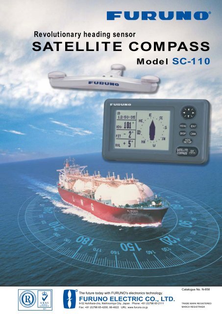
Revolutionary heading sensor<br />
SATELLITE COMPASS<br />
Model SC-110<br />
R<br />
The future today with FURUNO's electronics technology.<br />
FURUNO ELECTRIC CO., LTD.<br />
9-52 Ashihara-cho, Nishinomiya City, Japan Phone: +81 (0)798 65-2111<br />
Fax: +81 (0)798 65-4200, 66-4622 URL: www.furuno.co.jp<br />
Catalogue No. N-858<br />
TRADE MARK REGISTERED<br />
MARCA REGISTRADA
<strong>Furuno</strong>’s high-grade satellite compass<br />
with its superior heading accuracy<br />
for AIS, ECDIS, RADAR<br />
■ Heading information for ARPA, AIS,<br />
ECDIS, Scanning Sonar, Autopilot<br />
■ Heading accuracy ±0.6° exceeding<br />
IMO MSC.116(73) as a THD<br />
(Transmitting Heading Device)<br />
■ SOG, COG, ROT, pitch and roll<br />
■ Excellent follow-up rate of 45°/s<br />
exceeding requirements of high<br />
speed craft (20°/s)<br />
Compass Rose Mode<br />
■ High speed heading data output in<br />
IEC 61162-2 format<br />
■ Clear 4.5" silver bright LCD showing<br />
mimic compass rose with digital<br />
readouts<br />
■ Analog and digital data output for<br />
pitch and roll for ship’s motion<br />
correction<br />
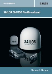
Principle<br />
With the SC-50, a ship's heading is determined by<br />
decoding the phase data in the GPS carrier frequency.<br />
In principle, a pair of antennas A1(ref) and A2(fore),<br />
each connected with an<br />
associated GPS engine and<br />
North<br />
processor, are installed along the<br />
ship's fore-aft line. The GPS<br />
systems at A1 and A2 calculate<br />
the range and azimuth to the<br />
Heading<br />
satellite.<br />
Antenna A3<br />
The difference in range between<br />
A1 and A2 is ∆λ + nλ where λ is<br />
θ<br />
19 cm and n* is automatically<br />
found during the initialization<br />
stage. A fraction of a carrier<br />
nλ<br />
wavelength, ∆λ, is processed by<br />
λ<br />
<strong>Furuno</strong>'s advanced kinematic<br />
technology in geographical<br />
survey, thus determining a vector ∆λ<br />
(range and orientation) A1 to A2,<br />
i.e., heading of ship relative to<br />
north.<br />
Antenna A1<br />
Vector to decide heading<br />
In reality, the third antenna is added to reduce the<br />
influence of pitch, roll and yaw, and five satellites are<br />
used to process 3D data (by 3rd sat), to reduce clock<br />
derived error (by 4th sat), and<br />
to calculate n in initial stage (by<br />
5th sat).<br />
Antenna A2<br />
Fore-aft line<br />
Difference between the<br />
range from satellite to<br />
antenna 1 and the range<br />
to antenna 2.<br />
If GPS signal is blocked by a<br />
tall building or under a bridge,<br />
the 3-axis vibrating-gyro rate<br />
sensors in the processor unit<br />
take the place of the satellite<br />
until all five satellites are in<br />
view. The rate sensors also<br />
contribute to regulating the<br />
heading data against pitch, roll<br />
and yaw together with<br />
the third antenna (A3 in the<br />
illustration).<br />
*Ambiguity "n" is resolved by<br />
LAMBDA algorithm developed by<br />
Prof. Teussen, Delft University of<br />
Technology, The Netherlands.
The SC-110 is an enhanced GPS-based compass<br />
designed for onboard equipment requiring a heading<br />
signal, such as ARPA, AIS, ECDIS, Scanning Sonar,<br />
Autopilot, etc. This equipment also provides all the<br />
necessary functions the latest GPS navigators do.<br />
Fallback arrangement by 3-axis vibrating-gyro rate<br />
sensor provides accurate and constant heading<br />
information even when the satellite signals are blocked<br />
under bridges or reduced by tall buildings. The SC-110<br />
also regulates the compass function when the ship is<br />
subject to pitching, rolling and yawing. The performance<br />
is not affected by ships’ speed, latitude, geomagnetism,<br />
etc. Settling time is almost instant and follow-up<br />
performance is excellent, achieving 45°/s (SOLAS HSC<br />
Code requires 20°/s as a minimum).<br />
In addition to the heading information and positional<br />
data, SOG (speed over ground), COG (course over<br />
ground) and ROT (rate of turn) are displayed. SOG is<br />
remarkably accurate by decoding the Doppler shift in the<br />
received satellite signals. The interface delivers true<br />
heading and course/speed over ground, rate of turn as<br />
well as GPS fix through up to 11 ports. The heading<br />
information is put out in IEC 61162-2 format at a high<br />
update rate of 25ms to satisfy the high speed data-output<br />
required in the special applications.<br />
The roll and pitch angle is also output both in analog and<br />
digital formats to the equipment, such as sonar,<br />
sounders etc. It is useful in offering the stable echo<br />
pictures by compensating the transmitted/received<br />
beams even in the rough seas. Thus, the SC-110 can be<br />
used as a highly accurate motion sensor.<br />
The SC-110 has a unique Set and Drift mode. When<br />
connected with a water-tracking speed-log, such as DS-<br />
80, it calculates set and drift (tide direction and speed) in<br />
the mode. The display helps a radar operator to manually<br />
enter set and drift for accurate sea stabilization pictures.<br />
The SC-110 consists of 3 antennas on a solid precision<br />
support, a processor unit, and a display unit. The triantenna<br />
system helps reduce the influence of ships’<br />
motions. There are no mechanical parts such as gimbals<br />
and rotating meters, thus the compass is free from<br />
regular maintenance.<br />
Heading Mode<br />
NAV Data Mode<br />
ROT Mode<br />
Steering Mode<br />
Set & Drift Mode<br />
(Current (Set and Drift) and Distance Run is selectable.)<br />
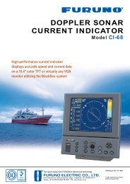
Interconnection<br />
Diagram<br />
Antenna Unit<br />
SC-1203F<br />
Display Unit<br />
SC-502<br />
DGPS<br />
Beacon Receiver<br />
GR-80<br />
Speed alarm/<br />
Heading alarm<br />
(Contact)<br />
Heading (Backup)<br />
/STW<br />
15/30/50 m<br />
Processor Unit<br />
SC-1101<br />
MJ-7 10 m<br />
IEC 611162-1/-2/AD-10<br />
IEC 611162-1/-2/AD-10<br />
IEC 611162-1/-2/AD-10<br />
IEC 611162-1/-2/AD-10<br />
IEC 611162-1/-2/AD-10<br />
AD-10<br />
Radar<br />
ECDIS<br />
AIS<br />
Autopilot (HCS/TCS)<br />
VideoPlotter<br />
Current Indicator<br />
Scanning Sonar<br />
Repeater Interface*<br />
AMI-GFV "KW-941" etc.<br />
for synchro<br />
AMI-GFV "KW-903-SX" etc.<br />
for step by step<br />
Analog Pitch/Roll<br />
Current Indicator<br />
Scanning Sonar<br />
Compass<br />
Rose*<br />
12-24 VDC<br />
Option or local supply<br />
* For further info, contact our depot
SPECIFICATIONS OF SC-110<br />
1. Accuracy<br />
Heading:<br />
±0.6° (95 % static accuracy)<br />
(IMO THD MSC.116(73) static<br />
accuracy: ±1.0° x secant Lat.)<br />
GPS: 10 m (95 %)<br />
DGPS: 5 m (95 %)<br />
2. Follow-up 25°/s rate-of-turn<br />
3. Settling time 4 min<br />
4. Interface<br />
Number of ports<br />
10 ports* 5 ports in AD-10 or<br />
10 ports in IEC 61162-1/-2<br />
* Number of ports is changed by system configuration.<br />
1 port AD-10 only<br />
Serial data sentence<br />
25/100/200 ms, 1s data rate:<br />
HDT, HDM(Heading), Patt(Pitch, Roll<br />
and Yaw), ROT(Rate of turn)<br />
1/2 s data rate: VHW(Heading), VTG, VBW(SOG),<br />
GGA, GLL, GNS(L/L), ZDA(UTC),<br />
GSA, GSV<br />
Log Output<br />
1 port: 200/400 p/nm (closure)<br />
Alarm Output 1 port: Alarm signal (closure signal)<br />
Heading Input 1 port: Backup Heading<br />
(AD-10/IEC 61162-1/-2)<br />
HDT, HDG, HDM, VBW, VHW, VLW<br />
DGPS Input 1 port: RTCM SC-104 format<br />
5. Receiver Type Twelve discrete channels.<br />
C/A code, all-in-view<br />
6. Receive Freq L1 (1575.42 MHz)<br />
7. Display Unit 4.5" diagonal 95 (W) x 60 (H)mm,<br />
120 x 64 pixels<br />
8. Display Mode Steering, Nav Data, Set and Drift,<br />
Compass Rose, ROT, Heading<br />
POWER SUPPLY 12-24 VDC, 15 W<br />
ENVIRONMENTAL<br />
IEC 60945 for EMC, Vibration, Temperature<br />
EQUIPMENT LIST<br />
Standard<br />
1. Display Unit SC-502 1 unit<br />
2. Antenna Unit with 15 m cable SC-1203F 1 unit<br />
3. Processor Unit SC-1101 1 unit<br />
4. Standard Spare Parts, Installation Materials 1 set<br />
Optional<br />
1. Antenna Cable, 15 m 20S0336-1, 30 m CP20-01700,<br />
50 m CP20-01710<br />
2. Flush Mount Kit S type CP20-17, F type CP20-29<br />
3. Repeater Interface for synchro or step by step<br />
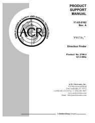
Display Unit<br />
125 4.9"<br />
209 8.2"<br />
175 6.9"<br />
Processor Unit<br />
Antenna Unit<br />
( 994)<br />
30<br />
1.2"<br />
200 7.9"<br />
0.6 kg 1.3 lb<br />
100 3.9"<br />
85 3.4"<br />
78 3.1"<br />
15 0.6"<br />
4- 6<br />
140 5.5" 32 1.3"<br />
3.6 kg 7.9 lb<br />
355 14.0"<br />
335 13.2"<br />
315 12.4"<br />
6.8 kg 15.0 lb<br />
860.8 33.9"<br />
(1016 40")<br />
265 10.4"<br />
100<br />
3.9"<br />
4 - 6<br />
103<br />
4.1"<br />
( 1150)<br />
115 4.5"<br />
(901 35.3")<br />
172 6.8"<br />
SPECIFICATIONS SUBJECT TO CHANGE WITHOUT NOTICE<br />
FURUNO U.S.A., INC.<br />
Camas, Washington, U.S.A.<br />
Phone: +1 360-834-9300 Telefax: +1 360-834-9400<br />
FURUNO (UK) LIMITED<br />
Denmead, Hampshire, U.K.<br />
Phone: +44 2392-230303 Telefax: +44 2392-230101<br />
FURUNO FRANCE S.A.<br />
Bordeaux-Mérignac, France<br />
Phone: +33 5 56 13 48 00 Telefax: +33 5 56 13 48 01<br />
FURUNO ESPANA S.A.<br />
Madrid, Spain<br />
Phone: +34 91-725-90-88 Telefax: +34 91-725-98-97<br />
FURUNO DANMARK AS<br />
Hvidovre, Denmark<br />
Phone: +45 36 77 45 00 Telefax: +45 36 77 45 01<br />
FURUNO NORGE A/S<br />
Ålesund, Norway<br />
Phone: +47 70 102950 Telefax: +47 70 127021<br />
FURUNO SVERIGE AB<br />
Västra Frölunda, Sweden<br />
Phone: +46 31-7098940 Telefax: +46 31-497093<br />
FURUNO SUOMI OY<br />
Helsinki, Finland<br />
Phone: +358 9 341 7570 Telefax: +358 9 341 75716<br />
02085Y Printed in Japan