GP1670F_1870F Operator's Manual - Furuno USA
GP1670F_1870F Operator's Manual - Furuno USA
GP1670F_1870F Operator's Manual - Furuno USA

Create successful ePaper yourself
Turn your PDF publications into a flip-book with our unique Google optimized e-Paper software.
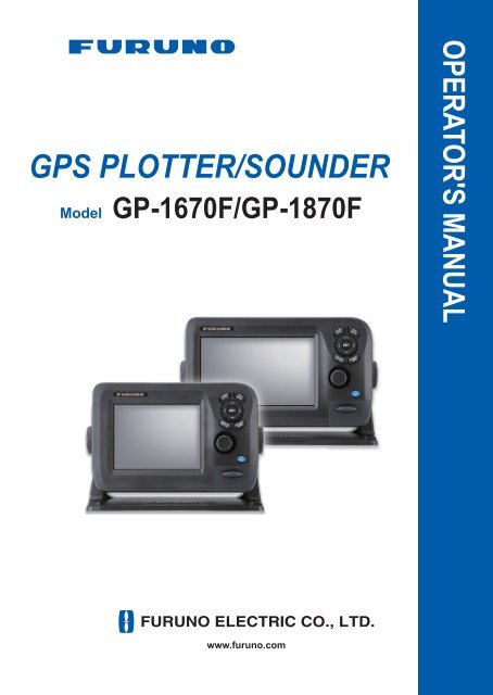
GPS PLOTTER/SOUNDERModelGP-1670F/GP-<strong>1870F</strong>OPERATOR'S MANUALwww.furuno.com
The paper used in this manualis elemental chlorine free.・FURUNO Authorized Distributor/Dealer9-52 Ashihara-cho,Nishinomiya, 662-8580, JAPANAll rights reserved. Printed in JapanPub. No. OME-44770-C(TAHA ) GP-1670F/GP-<strong>1870F</strong>A : JUN . 2012C : FEB . 15, 2013*00017659312**00017659312** 0 0 0 1 7 6 5 9 3 1 2 *
IMPORTANT NOTICESGeneral• This manual has been authored with simplified grammar, to meet the needs of international users.• The operator of this equipment must read and follow the descriptions in this manual. Wrong operationor maintenance can cancel the warranty or cause injury.• Do not copy any part of this manual without written permission from FURUNO.• If this manual is lost or worn, contact your dealer about replacement.• The contents of this manual and equipment specifications can change without notice.• The example screens (or illustrations) shown in this manual can be different from the screensyou see on your display. The screens you see depend on your system configuration and equipmentsettings.• Save this manual for future reference.• Any modification of the equipment (including software) by persons not authorized by FURUNOwill cancel the warranty.• SDHC is a registered trademark of SD-3C, LLC.• All brand and product names are trademarks, registered trademarks or service marks of theirrespective holders.How to discard this productDiscard this product according to local regulations for the disposal of industrial waste. For disposalin the <strong>USA</strong>, see the homepage of the Electronics Industries Alliance (http://www.eiae.org/)for the correct method of disposal.How to discard a used batterySome FURUNO products have a battery(ies). To see if your product has a battery, see the chapteron Maintenance. Follow the instructions below if a battery is used. Tape the + and - terminalsof battery before disposal to prevent fire, heat generation caused by short circuit.In the European UnionThe crossed-out trash can symbol indicates that all types of batteriesmust not be discarded in standard trash, or at a trash site. Take theused batteries to a battery collection site according to your nationallegislation and the Batteries Directive 2006/66/EU.CdIn the <strong>USA</strong>The Mobius loop symbol (three chasing arrows) indicates that Ni-Cdand lead-acid rechargeable batteries must be recycled. Take the usedbatteries to a battery collection site according to local laws.In the other countriesNi-CdPbThere are no international standards for the battery recycle symbol. The number of symbols canincrease when the other countries make their own recycle symbols in the future.i
SAFETY INSTRUCTIONSThe operator must read the safety instructions before attempting to operate the equipment.WARNINGCAUTIONIndicates a potentially hazardous situation which, if not avoided,could result in death or serious injury.Indicates a potentially hazardous situation which, if not avoided,could result in minor or moderate injury.Warning, CautionProhibitive ActionMandatory ActionWARNINGDo not open the equipment.The equipment uses high voltage thatcan cause electrical shock. Refer anyrepair work to a qualified technician.If water leaks into the equipment orsomething is dropped into the equipment,immediately turn off the powerat the switchboard.Fire or electrical shock can result.If the equipment is giving off smokeor fire, immediately turn off the powerat the switchboard.WARNINGFire or electrical shock can result.If you feel the equipment is actingabnormally or giving off strangenoises, immediately turn off thepower at the switchboard and contacta FURUNO service technician.Electrical current flows to the pins ofthe transducer connector when thepower is on, regardless of whetherthe transducer cable is connected ornot.WARNINGDo not disassemble or modify theequipment.Fire, electrical shock or serious injurycan result.Make sure no rain or water splashleaks into the equipment.Fire or electrical shock can result ifwater leaks into the equipment.Do not place liquid-filled containerson or near the equipment.WARNINGFire or electrical shock can result if aliquid spills into the equipment.Do not operate the equipment withwet hands.Electrical shock can result.Use the proper fuse.Use of the wrong fuse can cause fire orelectrical shock.If the transducer cable is not connected,cover the transducer connector with thesupplied cap to prevent electrical shock.ii
SAFETY INSTRUCTIONSCAUTIONDo no turn on the equipment with thetransducer out of water.The transducer can be damaged.The picture is not refreshed whenpicture advancement is stopped.Maneuvering the vessel in this conditioncan result in a dangerous situation.Adjust the gain correctly.Incorrect gain may give a wrong depthindication, which could result in adangerous situation.The data presented by this equipmentis intended as a source of navigationinformation.The prudent navigator never reliesexclusively on any one source ofnavigation information, for safety ofvessel and crew.The LCD panel is made of glass.Handle it with care.Injury can result if the glass breaks.Follow the compass safe distancesshown below to prevent interferenceto a magnetic compass.GP-1670FGP-<strong>1870F</strong>Standardcompass0.30 m0.30 mSteeringcompass0.30 m0.30 mWarning LabelDo not remove the label.To avoid electrical shock,do not removecover. No user-serviceable parts inside.Warning Labeliii
TABLE OF CONTENTSFOREWORD ...................................................................................................................ixSYSTEM CONFIGURATION ..........................................................................................xiEQUIPMENT LISTS.......................................................................................................xii1. OPERATIONAL OVERVIEW .................................................................................1-11.1 Controls...................................................................................................................... 1-11.1.1 Control description ......................................................................................... 1-11.2 RotoKey TM and Soft Controls .................................................................................... 1-51.3 How to Turn the Power On or Off............................................................................... 1-61.4 How to Adjust the Display Brilliance........................................................................... 1-61.5 2D Plotter Displays..................................................................................................... 1-61.6 The Cursor ................................................................................................................. 1-91.7 Navigation Data Boxes............................................................................................. 1-101.7.1 How to select the data to display in a box.................................................... 1-101.8 Home Screen (Display Selection) ............................................................................ 1-111.8.1 How to select a display ................................................................................ 1-111.8.2 How to switch the active screen................................................................... 1-111.8.3 How to customize the home screen............................................................. 1-121.8.4 Description of home screen displays ........................................................... 1-141.9 Display Range.......................................................................................................... 1-181.10 Orientation Mode...................................................................................................... 1-181.11 How to Move the Chart ............................................................................................ 1-191.12 Menu Operation ....................................................................................................... 1-201.13 Object Information.................................................................................................... 1-211.13.1 Simple information ....................................................................................... 1-211.13.2 Detailed information ..................................................................................... 1-211.14 Context-Sensitive Menus ......................................................................................... 1-221.15 Man Overboard (MOB)............................................................................................. 1-241.15.1 How to mark MOB position .......................................................................... 1-241.15.2 How to stop navigating to a MOB mark........................................................ 1-241.15.3 How to erase an MOB mark......................................................................... 1-241.16 How to Take a Screenshot....................................................................................... 1-241.17 Tide Information ....................................................................................................... 1-251.17.1 Tide height information................................................................................. 1-251.17.2 Tide stream information ............................................................................... 1-262. TRACK ...................................................................................................................2-12.1 How to Show, Hide all Track ...................................................................................... 2-12.2 How to Stop Recording Track .................................................................................... 2-12.3 How to Select Recording Method, Recording In-terval .............................................. 2-12.4 How to Change the Color of Your Boat’s Track ......................................................... 2-22.5 How to Change the Color of Your Boat’s Track with Sea Surface Temperature ....... 2-22.6 How to Hide, Show Track by Color ............................................................................ 2-22.7 How to Delete Track by Color .................................................................................... 2-32.8 How to Find Track Information ................................................................................... 2-33. POINTS ..................................................................................................................3-13.1 What is a Point? ......................................................................................................... 3-13.2 How to Enter a Point .................................................................................................. 3-13.2.1 How to enter a point at the current position ................................................... 3-13.2.2 How to enter a point at the cursor position..................................................... 3-2iv
TABLE OF CONTENTS3.2.3 How to enter a position manually on the plotter screen .................................3-33.2.4 How to enter a point from the Points List .......................................................3-33.3 How to Find Detailed Point Information......................................................................3-43.4 How to Move a Point ..................................................................................................3-43.4.1 How to move a point on the screen................................................................3-43.4.2 How to move a point from the Points List.......................................................3-43.5 How to Select Visibility for Points ...............................................................................3-53.6 How to Search, Sort Points on the Points List............................................................3-53.6.1 How to search points......................................................................................3-53.6.2 How to sort points...........................................................................................3-53.7 How to Filter Points by Shape on the Points List........................................................3-63.8 How to Delete Points..................................................................................................3-63.8.1 How to delete a point from the screen............................................................3-63.8.2 How to delete points from the Points List .......................................................3-64. ROUTES ................................................................................................................4-14.1 What is a Route?........................................................................................................4-14.2 How to Create a Route...............................................................................................4-14.2.1 How to create a route from the RotoKey menu ..............................................4-14.2.2 How to create a route from the Routes List....................................................4-24.2.3 How to create a route with the Easy Routing feature .....................................4-34.3 How to Extend a Route on the Screen .......................................................................4-64.4 How to Insert a Point on a Route on the Screen ........................................................4-74.5 How to Move a Point in a Route on the Screen..........................................................4-74.6 How to Delete a Point From a Route on the Screen ..................................................4-74.7 Routes List..................................................................................................................4-84.7.1 How to display the Routes List .......................................................................4-84.7.2 Functions available in the Routes List............................................................4-94.8 Route Report, Route Calculator ...............................................................................4-104.9 How to Display a Route on the Screen.....................................................................4-114.10 How to Connect Two Routes....................................................................................4-114.11 Simple Route Information.........................................................................................4-114.12 How to Rename a Route on the Screen...................................................................4-124.13 How to Delete Routes...............................................................................................4-124.13.1 How to delete a route on the screen ............................................................4-124.13.2 How to delete routes from the Routes List ...................................................4-125. NAVIGATION.........................................................................................................5-15.1 How to Navigate to a Quick Point...............................................................................5-15.2 How to Navigate to a Saved Point..............................................................................5-25.2.1 How to navigate to a saved point selected on the screen ..............................5-25.2.2 How to navigate to a point selected from the Points List................................5-25.3 How to Select a Route for Navigation.........................................................................5-25.3.1 On-screen route .............................................................................................5-25.3.2 Route selected from the Routes List ..............................................................5-35.3.3 How to start navigation from a point on a route..............................................5-35.4 Functions Available When You Follow a Route..........................................................5-45.4.1 Restart navigation ..........................................................................................5-45.4.2 Follow a route in reverse order.......................................................................5-45.4.3 Stop following a route.....................................................................................5-45.4.4 Skip a leg in a route........................................................................................5-46. MAP SETTINGS, 2D PERSPECTIVE/3D DISPLAYS ANDSATELLITE OVERLAY .........................................................................................6-16.1 Map Setup ..................................................................................................................6-16.2 2D Perspective Dispay ...............................................................................................6-5v
TABLE OF CONTENTS6.3 3D Display..................................................................................................................6-66.3.1 3D display description.................................................................................... 6-66.3.2 How to tilt and rotate the 3D display .............................................................. 6-76.3.3 How to make the 3D view clearer .................................................................. 6-76.4 Satellite Photo Overlay............................................................................................... 6-87. FISH FINDER OPERATIONS ................................................................................7-17.1 How the Fish Finder Works........................................................................................ 7-17.2 Fish Finder Display .................................................................................................... 7-27.3 How to Activate the Fish Finder ................................................................................. 7-37.4 How to Select a Display ............................................................................................. 7-37.4.1 How to select a single frequency or dual frequency....................................... 7-37.4.2 How to select a zoom display......................................................................... 7-47.4.3 A-scope display.............................................................................................. 7-57.4.4 Bottom discrimination display......................................................................... 7-67.5 Automatic Fish Finder ................................................................................................ 7-87.5.1 How the automatic fish finder works .............................................................. 7-87.5.2 How to select an automatic fish finder mode ................................................. 7-87.5.3 How to adjust the gain in the auto mode........................................................ 7-87.6 <strong>Manual</strong> Fish Finder Operation.................................................................................... 7-97.6.1 How to select a display range ........................................................................ 7-97.6.2 How to shift the range .................................................................................... 7-97.6.3 How to adjust the gain.................................................................................. 7-107.6.4 How to reduce clutter ................................................................................... 7-107.7 Picture Advance Speed............................................................................................ 7-117.8 How to Reduce Interference .................................................................................... 7-127.9 How to Erase Weak Echoes .................................................................................... 7-127.10 How to Measure Depth, Time Between Locations ................................................... 7-137.11 How to Balance Echo Strength ................................................................................ 7-137.12 White Marker............................................................................................................ 7-147.13 White Line ................................................................................................................ 7-147.14 Alarms ......................................................................................................................7-147.14.1 How to set an alarm ..................................................................................... 7-157.14.2 How to select the echo signal level that triggers the fish alarm ................... 7-157.15 ACCU-FISH TM ......................................................................................................... 7-167.15.1 Considerations for ACCU-FISH TM ............................................................... 7-167.15.2 How to activate ACCU-FISH TM , select display information ......................... 7-177.15.3 Fish size correction ...................................................................................... 7-177.16 Water Temperature Graph ....................................................................................... 7-187.17 FISH FINDER Menu................................................................................................. 7-197.18 Interpreting the Display ............................................................................................ 7-228. ALARMS ................................................................................................................8-18.1 ALARMS Menu .......................................................................................................... 8-18.2 Audio Alarm Conditions.............................................................................................. 8-28.3 Arrival Alarm...............................................................................................................8-28.4 XTE Alarm.................................................................................................................. 8-38.5 Temperature Alarm .................................................................................................... 8-38.6 Shear Alarm ............................................................................................................... 8-48.7 Depth Alarm ............................................................................................................... 8-48.8 Anchor Alarm ............................................................................................................. 8-58.9 Trip Alarm...................................................................................................................8-58.10 Speed Alarm .............................................................................................................. 8-58.11 Fuel Tank Alarm......................................................................................................... 8-68.12 Water Tank Alarm ...................................................................................................... 8-68.13 Black Water Tank Alarm ............................................................................................ 8-6vi
TABLE OF CONTENTS9. MEMORY CARD OPERATIONS ...........................................................................9-19.1 The Memory Card Screen ..........................................................................................9-19.2 How to Initialize SD Cards..........................................................................................9-19.3 How to Eject an SD Card............................................................................................9-29.4 How to Save Data to an SD Card...............................................................................9-29.5 How to Rename Files on an SD Card ........................................................................9-29.6 How to Delete Files from an SD Card ........................................................................9-39.6.1 How to delete individual files from an SD card...............................................9-39.6.2 How to delete all files from an SD card ..........................................................9-39.7 How to Import Data from an SD Card.........................................................................9-39.8 How to Process Screenshots .....................................................................................9-49.8.1 How to select source of screenshots (internal memory or SD card) ..............9-49.8.2 How to save screenshots in the internal memory to an SD card....................9-49.8.3 How to delete screenshots .............................................................................9-510. OTHER FUNCTIONS ..........................................................................................10-110.1 AIS Operations .........................................................................................................10-110.1.1 AIS target symbols .......................................................................................10-110.1.2 How to find AIS target information................................................................10-210.1.3 AIS activation range .....................................................................................10-210.1.4 CPA and TCPA alarms.................................................................................10-210.2 DSC Message Information .......................................................................................10-310.2.1 How to select a device for DSC message information .................................10-310.2.2 DSC message information ...........................................................................10-310.3 Stopwatch, Timer......................................................................................................10-410.4 How to Select Input, Output Data.............................................................................10-510.4.1 Input data .....................................................................................................10-510.4.2 Output data...................................................................................................10-610.5 Engine Display Setup (INSTRUMENTS menu)........................................................10-711. CUSTOMIZING YOUR UNIT ...............................................................................11-111.1 GENERAL Menu ......................................................................................................11-111.2 PLOTTER Menu.......................................................................................................11-211.3 SYSTEM Menu.........................................................................................................11-312. MAINTENANCE, TROUBLESHOOTING ............................................................12-112.1 Maintenance.............................................................................................................12-112.2 How to Replace the Fuse .........................................................................................12-212.3 Troubleshooting........................................................................................................12-212.4 GPS Status Display..................................................................................................12-412.5 How to Restore Defaults, Clear Memory..................................................................12-512.6 System Information...................................................................................................12-613. INSTALLATION ...................................................................................................13-113.1 Installation of Display Unit ........................................................................................13-113.2 Installation of Antenna Unit.......................................................................................13-213.3 Installation or Transducers .......................................................................................13-213.3.1 How to mount a transducer through the hull ................................................13-213.3.2 Transom mount transducer ..........................................................................13-513.3.3 How to mount a transducer inside the hull ...................................................13-613.3.4 Triducer ........................................................................................................13-713.4 Installation of Sensors (option)...............................................................................13-1213.4.1 Speed/temperature sensors ST-02MSB, ST-02PSB .................................13-1213.4.2 Temperature sensors .................................................................................13-1313.5 Wiring .....................................................................................................................13-1513.6 Initial Settings .........................................................................................................13-19vii
TABLE OF CONTENTS13.6.1 INSTALLATION SETTINGS menu............................................................. 13-1913.6.2 CAN bus input/output................................................................................. 13-21APPENDIX 1 MENU TREE .......................................................................................AP-1APPENDIX 2 ABBREVIATIONS, SYMBOLS ...........................................................AP-6APPENDIX 3 JIS CABLE GUIDE ...........................................................................AP-11SPECIFICATIONS .....................................................................................................SP-1PACKING LISTS.......................................................................................................... A-1OUTLINE DRAWINGS................................................................................................. D-1INTERCONNECTION DIAGRAM ................................................................................ S-1INDEX.......................................................................................................................... IN-1viii
FOREWORDA Word to GP-1670F, GP-<strong>1870F</strong> OwnersCongratulations on your choice of the FURUNO GP-1670F, GP-<strong>1870F</strong> GPS Plotter/Sounder. Weare confident you will see why the FURUNO name has become synonymous with quality and reliability.Since 1948, FURUNO Electric Company has enjoyed an enviable reputation for innovative anddependable marine electronics equipment. This dedication to excellence is furthered by our extensiveglobal network of agents and dealers.This equipment is designed and constructed to meet the rigorous demands of the marine environment.However, no machine can perform its intended function unless operated and maintainedproperly. Please carefully read and follow the recommended procedures for operation and maintenance.We would appreciate hearing from you, the end user, about whether we are achieving our purposes.Thank you for considering and purchasing FURUNO equipment.FeaturesThe GP-1670F and GP-<strong>1870F</strong> provide a totally integrated GPS receiver, color video plotter andcolor fish finder. The built-in GPS receiver provides highly accurate position, course and speedinformation. The fish finder presents vivid underwater images on a high quality LCD. The compactdisplay unit and antenna unit permit installation where space is limited.The main features areGeneral• Bright 5.7-inch (GP-1670F) or 7-inch (GP-<strong>1870F</strong>) color LCD with brilliance control.• Excellent viewing angles, even when wearing sunglasses.• Internal GPS receiver provides highly accurate position information (GPS, within 2.5 m, SBAS,within 2 m).• Customizable analog and digital displays show wind angle and speed, engine condition (speed,temperature, oil pressure, etc.), etc.• Large internal memory stores 30,000 track points, 30,000 points, 1,000 routes (500 waypoints/route).• SD card slot accepts SD and SDHC cards for external storage of data and settings.• Full range of alarms: Arrival, Anchor Watch, Cross-track Error, Speed, Depth, Temperature,Fish Alarm, Bottom Alarm, etc.• Man overboard (MOB) feature records latitude and longitude coordinates at the time of MOB.• CAN bus interface for the connection of GPS Receiver, Weather Station, FI-50 (instrument series),Satellite Compass, etc.• Accepts NMEA0183 input with optional NMEA data converter.• Internal GPS antenna available.• C-Map 4D charts available.ix
FOREWORDFish finder• Fish finder measures the depth to the bottom and displays underwater conditions in multi-colors*according to echo strength. A monochrome presentation shows the echoes in shades ofgray. (*Number of colors depends on network sounder, color sounder.).• Automatic and manual fish finder operation. Auto mode automatically adjusts range, gain andclutter ac-cording to purpose - fishing or cruising.• Wide variety of zoom modes for detailed observation of fish and bottom.• ACCU-FISH TM provides length and depth of individual fish. Appropriate transducer required.Other• AIS function (requires connection to an AIS transponder) provides navigational information fromAIS transponder equipped vessels within 50 nm.• Instrument displays (steering, engine, weather, and wind) with connection of relevant sensors.• DSC (Digital Selective Calling) function alerts to DSC messages received and position requests.(Requires DSC capable radiotelephone.)Open Source AcknowledgementThis product makes use of the following open source software:● FreeType (www.freetype.org)Portions of this software are copyright ©2009 The FreeType Project(www.freetype.org). All rights reserved.● libpng (http://www.libpng.org/)This software is based in part on the work of the Independent JPEG Group.● libjpeg (http://www.ijg.org/)We would like to thank each developer of the above-mentioned opensource software for their great contribution to the open source community.x
SYSTEM CONFIGURATIONThe environmental category of each unit is as follows:UnitDisplay unitGPS antenna unitTransducer, sensorOther unitsProtected from the weatherEnvironmental categoryExposed to the weather, or protected from the weather incase of internal antennaSubmerged in waterProtected from the weatherGP-1670FWater temp./speed sensorST-02MSB, ST-02PSBWater temp. sensorT-02MSB, T-02MTB, T-03MSBMatching BoxMB-1100*Transducer520-5PSD, 520-5MSD,525-5PWD, 525STID-MSD,525STID-PWDORInternal GPSantennaAntenna UnitGPA-017 orGPA-017SDisplay UnitGP-1670F* For connection to 1 kWtransducer (50B-6, 50B-6B,200B-5S, 50/200-1T,50/200-12M)Junction BoxFI-5002NMEA DataConverterIF-NMEA2K212-24 VDCRectifierPR-62CAN busequipmentNMEA 0183equipment100/110/220/230 VAC,1ø, 50/60 HzGP-<strong>1870F</strong>Antenna UnitGPA-017 orGPA-017SWater temp./speed sensorST-02MSB, ST-02PSBWater temp. sensorT-02MSB, T-02MTB, T-03MSBMatching BoxMB-1100*Transducer520-5PSD, 520-5MSD,525-5PWD, 525STID-MSD,525STID-PWDORInternal GPSantennaDisplay UnitGP-<strong>1870F</strong>* For connection to 1 kW transducer(50B-6, 50B-6B, 200B-5S,50/200-1T, 50/200-12M)Junction BoxFI-5002NMEA DataConverterIF-NMEA2K212-24 VDCRectifierPR-62CAN busequipmentNMEA 0183equipment100/110/220/230 VAC,1ø, 50/60 Hzxi
EQUIPMENT LISTSStandard supplyName Type Code no. Qty RemarksDisplay Unit GP-1670F - SelectDisplay Unit GP-<strong>1870F</strong> -oneInstallationMaterialsCP14-07100 000-021-070 1 set w/CP14-07101, MJ-A3SPF0013A-035C (power cable)Spare Parts SP14-03501 001-184-710 1 setAccessories FP14-03001 001-184-730 1 set For GP-1670FFP14-03201 001-183-120 1 set For GP-<strong>1870F</strong>Optional equipmentName Type Code no. RemarksReplacement Kit OP14-72 001-184-750Waterproofing Cap LTWCAP-WBDMMSA1 000-167-169-11Antenna UnitAntenna UnitGPA-017GPA-017SMast Mtg. Kit CP20-01111 004-365-780Antenna Cable Set CP20-01700 *30M* 004-372-110Antenna Cable Set CP20-01710 *50M* 004-372-120Transducer 520-5PSD 000-015-204 Thru-hull mount, plastic520-5MSD 000-015-212 Thru-hull mount, metal525-5PWD 000-146-966-01 Transom mount, plasticTriducer (transducerwith speed/ temperaturesensor)525STID-MSD 000-011-783 Thru-hull mount, metal525STID-PWD 000-011-784 Transom mount, plasticTransducer (1 Kw) 50B-6 000-015-042 10 m, 1 kW50B-6B 000-015-043 15 m, 1 kW200B-5S 000-015-029 10 m, 1 kW50/200-1T 000-015-170 10 m, 1 kW50/200-12M 000-015-171 10 m, 1 kWSpeed/ TemperatureSensorST-02MSB 000-137-986-01 Thru-hull type, metalST-02PSB 000-137-987-01 Thru-hull type, plasticxii
EQUIPMENT LISTSName Type Code no. RemarksTemperature SensorT-02MTB 000-040-026 Transom mount, 8 m cableT-02MSB 000-040-040 Thru-hull typeT-03MSB 000-040-027 Thru-hull type, 8 m cableMatching Box MB-1100 000-041-353 For connection to 1 kW transducerRectifier PR-62 000-013-484 100 VACRectifier PR-62 000-013-485 110 VACRectifier PR-62 000-013-486 220 VACRectifier PR-62 000-013-487 230 VACJunction BoxRight Angle MountingBaseL-angle MountingBaseHandrail MountingBaseFI-5002No.13QA330 001-111-910-10No.13-QA310 001-111-900-10No.13-RC5160 001-111-920-10Cable Assy. TNC-PS-/PS-3D-L15M-R 001-173-110-10Cable Assy. M12-05BM+05BF-010 001-105-750-10 w/connectors (light), 1 mCable Assy. M12-05BM+05BF-020 001-105-760-10 w/connectors (light), 2 mCable Assy. M12-05BM+05BF-060 001-105-770-10 w/connectors (light), 6 mCable Assy. M12-05BFFM-010 001-105-780-10 w/connectors (light), 1 mCable Assy. M12-05BFFM-020 001-105-790-10 w/connectors (light), 2 mCable Assy. M12-05BFFM-060 001-105-800-10 w/connectors (light), 6 mCable Assy. CB-05PM+05BF-010 000-167-968-10 w/connectors (heavy), 1 mCable Assy. CB-05PM+05BF-020 000-167-969-10 w/connectors (heavy), 2 mCable Assy. CB-05PM+05BF-060 000-167-970-10 w/connectors (heavy), 6 mCable Assy. CB-05BFFM-010 000-167-971-10 w/connectors (heavy), 1 mCable Assy. CB-05BFFM-020 000-167-972-10 w/connectors (heavy), 2 mCable Assy. CB-05BFFM-060 000-167-973-10 w/connectors (heavy), 6 mMicro T-connector SS-050505-FMF-TS001 000-168-603-10 Micro style: 3Mini/Micro T-connectorNC-050505-FMF-TS001 000-160-507-10 Mini style: 2, micro style: 1Termination Resistorr(Mini)Termination Resistor(Micro)LTWMN-05AMMT-SL8001LTWMC-05BMMT-SL8001000-160-508-10 Mini style, male, terminationresistor000-168-604-10 Micro style, male, terminationresistorxiii
EQUIPMENT LISTSName Type Code no. RemarksTermination Resistor(Mini)Termination Resistor(Micro)LTWMN-05AFFT-SL8001LTWMC-05BFFT-SL8001000-160-509-10 Mini style, female, terminationresistor000-168-605-10 Micro style, female, terminationresistorInline Terminator FRU-0505-FF-IS 001-077-830-10Cable Assy. 02S4147-1 000-141-082 For speed/temp. sensorInner Hull Kit 22S0191 000-082-598 w/installation instructions,not usable with the bottomdiscrimination displayNMEA Data ConverterIF-NMEA2K2xiv
1. OPERATIONAL OVERVIEW1.1 Controls1.1.1 Control descriptionThe controller for this system is either the GP-1670F or the GP-<strong>1870F</strong>. A key that hastwo text labels has two functions. The top label is the main function and the bottomlabel is the secondary function. Short-push to access the main function and long-push(approximately three seconds) to access the secondary function.You operate the chart plotter with• Keys• CursorPad• RotoKey TM• Menus, where you select options• Context-sensitive menus, where you select options• Lists, where you can edit itemsWhen you operate a key, a single beep sounds to tell you correct operation. If you donot need the key beep, you can deactivate it from the menu.How to remove the hard coverPut fingers under notch at bottomof cover and pull toward you.POINTS/GO TO keyCursorPadHOME/CTRL keyESC/MENU keyENT keyEVENT/MOB keyRotoKey TMPOWER/BRILL keyBehind cover:- SD card slot- USB micro connector- RESET buttonPictured: GP-<strong>1870F</strong>ControlPOWER/BRILL keyDescriptionShort press: Adjust LCD brilliance.Long press: Turn the power on or off.1-1
1. OPERATIONAL OVERVIEWControlRotoKey TMPOINTS/GOTO keyEVENT/MOB keyENT keyESC/MENUkeyHOME/CTRL keyCursorPadDescriptionShort push: Display the base RotoKey soft controls for the currentmode.Long push: Display the full RotoKey soft controls for the current mode.Rotate: Zoom in or out the display range for the chart. Select a menuitem. Select the display range for the fish finder.Short press: Put a point at the cursor position.Long press: Set cursor position as destination.Short press: Put a point at the current position.Long press: Put an MOB (ManOverBoard) mark at current position.Confirm current operation.Short press: Escape from current operation. Silence an audio alarm.Long press: Open the menu.Short press: DIsplay the home screen, to select a display.Long press: Switch the active display in combination modes.Moves the cursor and scrolls the screen, in the direction of the arrowpressed.SD card slot: Card drive for SD card (chart card and memory card).Micro USB connector: Connects to a PC for maintenance. (Mouse or USB flash memorycannot be connected.)RESET button: Resets the program. Should the screen freeze press this button to restart.SD cardsThe SD cards store ship’s tracks, routes, points, settings, etc. The unitaccepts SD and SDHC (Secure Digital High Capacity) type cards andthe maximum capacity is 32 GB.To set a card in the slot, insert the card label side up. If the card does not go in easily,do not use force. Push the card until the card is in position.To remove a card, Select [Eject SD card] from the full RotoKey menu.Remove the card (with your fingers) after the message "You can eject SD card safely."appears.Care and handling of SD cards• Handle the cards carefully; rough handling can damage the card and destroy itscontents.• Make sure the cover is closed at all times. Insert the card fully or remove thecard; the cover cannot be closed if the card is inserted partially.• Remove a card with only your fingers. Do not use metal instruments (like tweezers)to remove the card.• Do not remove a card during the reading of the card or writing to the card, to preventdamage to the card and loss of the data stored on the card.• If water is at the bottom of the cover, DO NOT open the cover. Remove the waterwith a dry cloth completely and then open the cover.1-2
1. OPERATIONAL OVERVIEWTested SD cardsThe SD cards tested for use in this equipment are listed in the table below.Maker, TypeSize2 GB 4 GB 8 GB 16 GB 32 GBADTECAD-SDH (SD) [AD-SDH2G]YBUFFALORSDC-S (SD) [RSDC-S2G]RSDC-G Hi-Performance (SD) [RSDC-G2G]YYHagiwara SystemT series (SD) [PSDB0487A]M series Super High Speed (SD) [PSDB0486A]YYI-O DATAI-O DATA (SD) [SD-2G]I-O DATA Super High Speed (SD) [SDP-2G]YYKingstonKingston (SD) [SD/2GBFE]YKingston (SDHC) CLASS 4 [SD4/16GB]YKingston (SDHC) CLASS 4 [SD4/32GB]YPanasonicPanasonic PRO HIGH SPEED (SD) [RP-SDK02GJ1A]Panasonic HIGH SPEED (SD) CLASS 2[[RP-SDR02GJ1A]YYPanasonic HIGH SPEED (SDHC) CLASS 4[RP-SDM04GK1K]YPanasonic HIGH SPEED (SDHC) CLASS 4[RP-SDM08GK1K]YPanasonic HIGH SPEED (SDHC) CLASS 4[RP-SDM16GK1K]Panasonic (SDHC) CLASS 4 [RP-SDP16GJ1K]Panasonic (SDHC) CLASS 10 [RP-SDW16GJ1K]YYYPanasonic PRO HIGH SPEED (SDHC) CLASS 6[RP-SDV04GK1K]YPanasonic PRO HIGH SPEED (SDHC) CLASS 6[RP-SDV08GK1K]Ypqipqi (SD) [QSDS-2G]Y1-3
1. OPERATIONAL OVERVIEWMaker, TypeSize2 GB 4 GB 8GB 16 GB 32GBSan DiskSanDisk (SD) [SDSDB-2048-J60]YSanDisk (SDHC) [SDSDBR-4096-J85]YSanDisk Ultra II (SDHC) CLASS 4 [SDSDRH-8192-903]YSanDisk Ultra II (SD) [SDSDH-2048-903]YSanDisk Ultra II (SDHC) [SDSDRH-4096-903]SanDisk Extreme III (SDHC) [SDSDRX3-4096-903]YYSanDisk Extreme (SDHC) [SDSDX3-016G-J31A]YSanDisk Extreme (SDHC) [SDSDX3-032G-J31A]YSILICON POWER(SDHC) [SP016GBSDH006V10]Y(SDHC) [SP032GBSDH006V10]YTOSHIBA(SD) CLASS 4 [SD-B002GT4]Y1-4
1. OPERATIONAL OVERVIEW1.2 RotoKey TM and Soft ControlsThe main function of the RotoKey TM is to display the RotoKey menu, a set of revolvingsoft controls that change with the operating mode. There are two sets of RotoKeymenus: base and full. A short push of the key shows the base set for the current mode,and a long push displays the full compliment of soft controls for the current mode.When the full set is active, a scroll bar appears to show your location in the menu.Scroll barBase soft controlsFull soft controlsThere are two categories of soft controls, toggle and drop-down list. Category is distinguishedby an icon at the left edge of the soft controls.Soft controlcategoryToggleExampleFunction ON (green)DescriptionA soft control with a lamp is a toggle control.The lamp is green when the functionis ON; gray when OFF.Function OFF (gray)Drop-down listA soft control with a left arrow has a dropdownlist that has a set of functions tochoose from.To operate the soft controls, push the RotoKey TM to show the RotoKey menu. Rotatethe key to select a soft control then push the key to do the function labeled on the softcontrol. When you search through the RotoKey menu, the selected soft control is longerthan other soft controls, its color is light blue and the soft control name is in whitecharacters. The soft controls automatically disappear from the screen if not operatedwithin approx. six seconds. To erase the soft controls manually, press the ESC/MENUkey.Note 1: Hereafter, this manual only implies the use of the RotoKey TM in soft controloperations. We write “Open the RotoKey menu then select [soft control name]” whereyou would rotate and push the key to select and do a function.Note 2: Where “key” is not preceded by a key name, this means the RotoKey TM .1-5
1. OPERATIONAL OVERVIEW1.3 How to Turn the Power On or OffTo turn the power ON, press approx two seconds. Release when the FURUNOlogo appears. It takes approx. 25-30 seconds to start the system, in the sequenceshown below.1) If some data is missing or is out of date, a message states the missing component.Contact your dealer for details.2) If a C-MAP chart card is inserted, chart information is checked to see if it is up todate. If the chart is not up to date, the message "The chart data is out of data, andmay be unsafe for navigation, which could place you and others at risk..." If thismessage appears contact your dealer to get up-to-date charts.3) The unit beeps and shows the “Warnings - Limitations on Use” screen. Read theinformation then push the RotoKey TM to start operation.To turn the power OFF, pressappears.until the message “Shutting down, please wait...”1.4 How to Adjust the Display BrillianceYou can adjust the display brilliance as follows:1. Press the key to show the [Backlight Brill]adjustment window.2. Press the same key again to adjust the brilliancecyclically. The window shows the current levelwith analog and digital displays. The brilliancecan also be adjusted with the RotoKey TM . Rotatethe key clockwise to increase the brilliance, or counterclockwise to decreasethe brilliance.3. Press the ESC/MENU key to close the window.1.5 2D Plotter DisplaysThe plotter provides a small world map. More detailed charts for your area are optionallyavailable. The plotter section has functions to enter waypoints, and create andplan routes.The plotter receives position information from the internal GPS receiver. Your positionis marked on the screen with the own ship icon. You can change the shape of the iconfrom the menu. Waypoints and routes you have entered are shown on the display. Youcan move, delete and edit the waypoints and routes from a context-sensitive menu orthrough the menu.The plotter display also• Plots the track of your boat.• Measures distances and bearings.• Marks man overboard (MOB) position.• Controls alarm functions.• Follows routes.1-6
1. OPERATIONAL OVERVIEW2D plotter display, vector chartA vector chart is a series of points and lines that make up the features on a chart. Vectorcharts look computer generated. Details on the chart can be turned on and off. Objectson the chart can be clicked on to learn more details. Depths can be monitored towarn before grounding. When zooming in and out of a vector chart only the geographicalfeatures grow larger or smaller where text keeps it's same size and orientation.Vector charts lack most topographical features.Position fix state*Alarm iconOrientation mode (North Up, Course Up,Auto Course Up, Heading Up)CompassCOG line(black)MOBmarkL/L gridGPS 3DHeadingline(red dashed line)Own shipmarker (black)Track(default coloris red)Cursor(inactive, red)MOB180°T14.2 NM20 NMMOB box(Bearing and range to MOB position)Range scale*Position fix state indicationsGPS 2D: 2D position fixGPS 3D: 3D position fixGPSW2D: WAAS 2D position fixGPSW3D: WAAS 3D position fixNO FIX: No position dataSIM: Simulator mode1-7
1. OPERATIONAL OVERVIEW2D plotter display, vector/satelliteThe vector chart plus a satellite photo. See chapter 6 for how to adjust the satellite display.2D plotter display, rasterA raster chart is a direct copy or scan of an existing paper chart. Raster charts lookidentical to paper charts. All information contained within the chart is printed directlyon it. What you see is what you get. When zooming in and out of a raster chart everythingon the chart grows larger or smaller. When rotating a raster chart every thing onthe chart rotates.1-8
1. OPERATIONAL OVERVIEW1.6 The CursorThe cursor has the functions shown below.• Find, when put on respective item:• Position, range and bearing to cursor location• Point information• Route information• Track information• AIS target information• DSC information• Tide information• Object information• Select a position for a waypoint on the plotter display.• Select an item. For example, a waypoint on the plotter display.The appearance of the cursor depends on its state - active or inactive.To move the cursor, press any of the four arrows on the CursorPad. The cursormoves in the direction indicated on the pressed arrow.: Active : Inactive (red)How to find cursor position, range and bearing to cursor positionPress any of the four arrows on the CursorPad to move the cursor in the direction indicatedon the pressed arrow. The cursor position and the distance and bearing fromyour boat to the cursor position are displayed.Cursor position inlatitude and longitudeDistance tocursor positionPosition43°59.2157'N135°16.6498'EDST NM BRG T10.5 185°Bearing tocursor positionHow to find current position, SOG and COGPut the cursor on the own ship icon to find current position, SOG and COG.Cursor position inlatitude and longitudeSpeed overthe groundPosition43°22.1834'N134°26.3465'ESOG kn COG T12.2 155°Course overthe ground1-9
1. OPERATIONAL OVERVIEW1.7 Navigation Data BoxesThe navigation data boxes, displayed at the bottom of the screen, show various navigationdata fed from the sensors connected to the display unit. Two or four boxes canbe displayed and you can freely change the data shown in each box. The data thatyou can show depends on your system configuration. The boxes can be shown or hiddenwith the [Nav Data] soft control.knNote: Waypoint name, distance to WPT, bearing to WPT, XTE, TTG and ETA are notavailable unless you are navigating to a point or route. Bars (--) are shown in the respectivebox when the data is not available.1.7.1 How to select the data to display in a box1. Open the full RotoKey menu then choose [Select Data]. The background color ofall but one of the boxes is grey.Box not greyed out iscurrently selected box.kn2. Rotate the RotoKey TM to select the data box to change then push the key to showthe [Select Data] (data category) window.3. Select a data box category, and a window with choices relevant to your selectionappears.DSTBRGNavigationSpeed/BearingDepth Environment Wind4. Select the data desired.1-10
1.8 Home Screen (Display Selection)1. OPERATIONAL OVERVIEW1.8.1 How to select a displayThe home screen has eight displays from which to choose. Press the HOME/CTRLkey to show the home screen. Operate the CursorPad or rotate the RotoKey TM toselect a display. The current selection is circumscribed with a red rectangle. Press theRotoKey TM or ENT key to confirm your selection.1.8.2 How to switch the active screenIn multi-split screens, you can switch the active screen with the HOME/CTRL key.Long-press the key to select the screen to make active. The active screen is circumscribedwith a red rectangle.MLongpressACTIVEAC IVEACTIVECTRL CTRLLongpress1-11
1. OPERATIONAL OVERVIEW1.8.3 How to customize the home screenThe home screen has seven screens that you can customize. (The full-screen plotterdisplay cannot be customized. If you try to customize this display, the message “Can’tcustomize this display.” appears.) You can split the screen in up to four separate segments.In each segment you can select the following displays:ScreenSingle screenHalf screenDisplays availablePlotter, fish finder, tide and celestial, GPS statusPlotter, fish finder, highway, wind angle meter, meter (speed, watertemperature/temperature, engine), graph, tankQuarter screenNavigation data, steering, wind angle meter, meter (same choices asfor half screen), graph, tankFollow the procedure below to customize a home screen. As an example, the procedureshows how to put the plotter display and fish finder display on the halves screen.1. Press the HOME/CTRL key to show the home screen.2. Use the RotoKey TM to select the screen to customize.3. Long-push the RotoKey TM to show the [PAGE CUSTOMIZATION] screen.4. Select the division desired then push the RotoKey TM . For example, select thehalves screen. The [DISPLAY CUSTOMIZATION] screen appears.The rectangle cursor (red) in the screen selection area circumscribes the screendivision currently selected. If necessary, use the RotoKey TM to select a screendivision.1-12
1. OPERATIONAL OVERVIEW5. Select a display then push the RotoKey TM . For example, select the plotter display.The chosen display appears at the location selected and the rectangle cursormoves to the adjacent screen.6. Select a display for the right half then push the RotoKey TM . For example, selectthe fish finder display. Control is returned to the home screen, where you can seethe result of your selection.Plotter, fish finder display1-13
1. OPERATIONAL OVERVIEW1.8.4 Description of home screen displaysFull screen displaysPlotter: See page 1-7.Fish finder: See chapter 7.Tide & Celestial: Your plotter provides for calculation of the tide heights for any date.Additionally this display shows the time of sunrise, sunset, moonrise and moonset.See section 1.17.GPS status display: The GPS status display shows the location and RX signalstrength of each satellite being received. See section 12.4.Half screen displaysThe half screen displays provide the plotter display, highway display, navigation data,and navigation data plus a graphic display (graph or meter). In most displays the datacan be changed. See the end of this section for how to change data.Plotter: See page 1-7.Highway: The highway display provides a graphic presentation of your boat’s trackalong intended course, and is useful for monitoring ship's progress toward a waypoint.You can zoom in and zoom out the display by rotating the RotoKey TM . The verticalline at the center of the screen is your intended course and the name of the waypointyou are steering to is at top of the line. Steer your boat so that the own ship marker inthe XTE scale stays near zero. If you go off course, the direction to steer to return toyour course is indicated with the color-coded steer direction arrow. The arrow is redwhen you should steer to port; green when you should steer to starboard. The widthof the navigation lane (black area in the figure below) and the XTE (cross-track error)range scale are equal to the XTE alarm setting. In the example illustration, the boat isoff course to the starboard side by approx 0.3 nm. Rotate the RotoKey TM to changethe display range.Display rangeSteer direction arrow (red)(Steer left to keep course.)Note: Both steer directionarrows are not displayed at thesame time in actual operation.They are displayed here fordemonstration purpose.XTE range scale(equal to XTE alarm range)Navigation data(selectable)WPT nameWaypoint (red)Steer direction arrow (green)(Steer right to keep course.)Own ship marker (red)1-14
1. OPERATIONAL OVERVIEWWind meter+navigation data x2: The wind meter providesanalog and digital indications of wind angle. The wind meteris fixed; however, the two boxes of navigation data can bechanged.knMeter+navigation data x2: This display provides a meterplus two navigation data boxes. The meter and boxes can bechanged. The example at right shows the appearance of theSOG meter.knknGraph+navigation data x2: The graph (depth, water temperature,air temperature, atmospheric pressure, SOG, windspeed) plots selected data in a five-minute period. The navigationdata indications can be changed freely.Tank level: The tank level of fuel, water and black water areshown in both analog and digital formats. The analog indicationis colored according to tank level as follows:ColorFuel, waterTank levelBlack waterGreenYellowEqual to or greaterthan 40%Between 20% and39%Equal to or lessthan 60%Between 61% and80%Red Less than 20% Greater than 80%1-15
1. OPERATIONAL OVERVIEWQuarter screensThe figure below shows the available quarter screens. Like with the half screens youcan select the navigation data to display in a quarter screen.Navigation data x1 Navigation data x2 Navigation data x3Navigation data x4 Steering Wind angleMeter x1 (ex. SOG)Meter x4GraphGraph, navigation data x2Navigation data x2, graphTank1-16
1. OPERATIONAL OVERVIEWHow to select the data to display in a quarter screen, half screen navigation data1. Display a home screen that has a quarter screen or a halfscreen with navigation data.2. Long press the HOME/CTRL key to select the data display tochange. The selected indication is circumscribed with a redrectangle.3. Choose [Select Data] from the RotoKey menu.4. Rotate the RotoKey TM to select the indication to change thenpush the RotoKey TM . The [Select Data] window shows thedata categories available.5. Rotate the RotoKey TM to select a category then push the key.The right figure shows the choices available with [Navigation].6. Select desired data.DSTDST-EBRGEngine indicationsThe following engine indications are available, in the quarter screen.• Engine boost pressure• Engine coolant pressure• Engine load• Engine oil pressure• Engine oil temperature• Engine speed• Engine temperature• Engine trim• Fuel pressure• Fuel rate• Total engine hours• Transmission oil pressure• Transmission temperatureEngine instance numberThe engine instance number appears on all engine-related indications.E-SPD 2RPMEngine Instance No.0: Single engine, or PORT engine with 2 or 3 engines1: STARBOARD engine with 2 engines,or CENTER engine with 3 engines2: STARBOARD engine with 3 enginesNote: This is the standard numbering method,Different methods can be applied.1-17
1. OPERATIONAL OVERVIEW1.9 Display RangeYou can change the chart scale to change the amount of informationshown, or zoom in or out at the location you select,in the plotter and steering displays. The selected chart scaleappears at the bottom right-hand position on the screen. Theavailable ranges depends on latitude and chart area.To select a display range, rotate the RotoKey TM . Clockwiseto increase the range; counterclockwise to decrease therange.20 NMRange scale1.10 Orientation ModeThe chart can be shown in head-up, north-up, courseupand auto course-up. Select an orientation modefrom the RotoKey menu: Select [Mode] followed by[Head Up], [North Up], [Course Up] or [Auto CourseUp]. The selected mode appears at the top right-handposition.Description of orientation modesGPS 3DOrientation modeHead-up: Displays the chart with the current compass heading of your boat at the topof the screen. The heading data from a compass is required. When the headingchanges, the ship icon remains fixed, and the chart picture rotates according to heading.North-up: North is at the top of the screen. When your heading changes, the ship iconmoves according to heading. This mode is for long-range navigation.Course-up: The chart picture is stabilized, and shown with your current course (overground) at the top of the screen. The ship icon moves with the heading. If you selecta new course, the picture resets to display the new course at the top of the screen. Ifno destination is set, the course is upward on the screen at the moment course-up isselected.PT000015 NM1-18
1. OPERATIONAL OVERVIEWAuto course-up: The course or heading is at the top of screen at the moment the autocourse-up mode is selected.PT000015 NM1.11 How to Move the ChartMove the chart in the following conditions.• Your boat is not in the current area.• Take a look at another area.• Enter a point at another location.To move the chart, press and hold down the CursorPad to move it to an edge of thedisplay. The chart shifts in the direction opposite to the arrow pressed.To return your boat to the screen center, select [Center] from the RotoKey menu.1-19
1. OPERATIONAL OVERVIEW1.12 Menu OperationThis section shows you how to operate the menu. There are eight menus, [General],[Map], [Plotter], [Alarms], [System], [Fish Finder], [Instruments] and [Interface].1. Long-push the ESC/MENU key to show the main menu.2. Rotate the RotoKey TM to select a menu then push the key or the ENT key to displaythat menu. (A menu can also be selected with the CursorPad.) For example,select the [General] menu.3. Rotate the RotoKey TM to select a menu item then push the key to showthe corresponding options window. For example, select [Font Size] andthe options window shown right appears.LargeSmall4. Rotate the RotoKey TM to select an option then push the key to confirm setting.Some menu items require entry of alphanumeric data. See the procedure below.How to enter alphanumeric data1) Use the right and left arrows on the CursorPad to select the digit or characterto change.2) Use the up and down arrows on the CursorPad to select a numeric value.3) Repeat steps 1) and 2) to enter remaining numeric data.1-20
1. OPERATIONAL OVERVIEW4) Press the ENT key to save the data.5. Press the ESC/MENU key to close the menu. (Several presses may be requireddepending on your location in the menu.)Note: Hereafter, this manual only implies the use of the RotoKey TM in menu operations.We write “Select [menu name, menu item or menu option]” where you would rotateand push the key to select and set a menu item.1.13 Object Information1.13.1 Simple informationSimple information is available for points, track, routes, objects, AIS targets, DSCmarker and tide. Simply put the cursor on the item for which you want to find information.The figure below shows simple information for a point, track, route and chart object.PT0001143°59.2157'N135°16.6498'EDST NM BRG T10.5 185°Point informationTrack InformationTime 02-24-12 12:46PMTemp 11.3ºFDepth 85.7 mFish size 21, 18, 15, 07 cmBottom type Mud 60%NameCommentTrack informationRT000112:20PM 03-16-12Tower White 85 FeetFlashing(1) White. 15 Seconds85 Feet 24 MilesObject information(chart object)Route information1.13.2 Detailed informationDetailed information is available for points, routes and chart objects. Put the cursor onthe item for which you want to find detailed information then press the ENT key toshow the context-sensitive menu. Select one of the following depending on your selection:• Point: [DETAILED]• Route: [INFO]• Chart object: [FULL INFO]The right figure shows detailed information for apoint.Name PT0001Position 34º41.006N135º41.629ETime 02-24-12 12:46PMTemp 11.3ºDepth 85.7 mFish size 21, 18, 15, 07 cmBottom type Mud 60%Comment FURUNODetailed point information1-21
1. OPERATIONAL OVERVIEW1.14 Context-Sensitive MenusThe context-sensitive menus let you quickly access the functions related to the cursorselecteditem. Select an applicable item then press the ENT key to show the relatedcontext-sensitive menu. Use the RotoKey TM to select a function. The table belowshows the context-sensitive menus available in each category.Item Context-sensitive menu DescriptionPointPoint (set asdestination)Point inRoute (activeroute)MOVEDELETEEDITGOTODETAILEDEASY ROUTINGSTOPRESTARTDETAILEDMOVESKIPACTIVATE FROM[MOVE]: Move the point selected.[DELETE]: Delete the point selected.[EDIT]: Edit the point selected.[GOTO]: Go to the point selected.[DETAILED]: Find detailed information about thepoint selected.[EASY ROUTING]: Get easy routing calculationsto the point selected.[STOP]: Stop navigating to the point selected.[RESTART]: Restart navigation to the point selected.[DETAILED]: Get detailed information about thepoint selected.[MOVE]: Move the point selected.[SKIP]: Skip the point selected.[ACTIVATE FROM]: Start navigating from thepoint selected.Point inRoute (inactiverouteMOVEDELETEGOTOEASY ROUTING[MOVE]: Move the point selected.[DELETE]: Delete the point selected.[GOTO]: Start navigating from the point selected.[EASY ROUTING]: Get easy routing calculationsfor the route selected.Chart ObjectOwn BoatFULL INFOLAT/LONEASY ROUTINGCOG LINEHEADING LINERECORD TRACKSHIP ICONEASY ROUTINGInfiniteOffOnIcon 1[FULL INFO]: Get full information about the chartobject selected.[LAT/LON]: Save the position selected as a point.[EASY ROUTING]: Get easy routing calculationsto the chart object selected.[COG LINE]: Show or hide the COG vector.[HEADING LINE]: Show or hide the heading line.[RECORD TRACK]: Stop or start recording yourboat’s track.[SHIP ICON]: Change the ship icon.[EASY ROUTING]: Get easy routing calculations.1-22
1. OPERATIONAL OVERVIEWItem Context-sensitive menu DescriptionRoute (active)Route (inactive)TrackSTOPRESTARTREVERSEINSERTEXTENDINFOGOTOREVERSEINSERTEXTENDRENAMEDELETEINFOEASY ROUTINGHIDEDELETEEASY ROUTING[STOP]: Stop navigating the active route.[RESTART]: Restart navigating the active route.[REVERSE]: Follow the points in the active routein reverse order.[INSERT]: Add a new point to the cursor positionof the active route.[EXTEND]: Add a new point to the end of the activeroute.[INFO]. Get information about the active route.[GOTO]: Activate the route selected.[REVERSE]: Follow the points in the route in reverseorder.[INSERT]: Add a new point to the cursor positionof the route selected.[EXTEND]: Add a new point to the end of the routeselected.[RENAME]: Rename the route selected.[DELETE]: Delete the route selected.[INFO]: Get information about the route selected.[EASY ROUTING]: Get easy routing calculationsfor the route selected.[HIDE]: Hide the track in the selected color.[DELETE]: Delete the track in the selected color.[EASY ROUTING]: Get easy routing calculationsfor the track.Points ListRoutes ListMOB mark(on screen)EDITDELETEPLOTMODEGOTOEDITDELETEPLOTREVERSEREPORTGOTOSTARTDELETE[EDIT]: Edit the point selected.[DELETE]: Delete the point selected.[PLOT]: Show the point selected on the plotterdisplay.[MODE]: Select the visibility for the point selected.[GOTO]: Go to the point selected.[EDIT]: Edit the route selected.[DELETE]: Delete the route selected.[PLOT]: Show the route selected on the plotterdisplay.[REVERSE]: Follow the points of the route selectedin reverse order.[REPORT]: Display the route report for the routeselected.[GOTO]: Go to the route selected.[START]: Go to the MOB mark selected.[DELETE]: Delete the MOB mark selected.MOB mark(on PointsList)PLOTDELETEGOTO[PLOT]: Show the MOB mark selected on the plotterdisplay.[DELETE]: Delete the MOB mark selected.[GOTO]: Go to the MOB mark selected.1-23
1. OPERATIONAL OVERVIEWItem Context-sensitive menu DescriptionScreenshots(IN-TERNAL)Screenshots(SDCARD)SAVEDELETERENAMEPREVIEWLOADDELETERENAMEPREVIEW[SAVE]: Copy the screenshots in the internalmemory to the SD card.[DELETE]: Delete the screenshots.[RENAME]: Give the file a new name.[PREVIEW]: Show the screenshots selected onthe screen.[LOAD]: Copy the screenshots in the SD card tothe internal memory.[DELETE]: Delete the screenshots.[RENAME]: Give the file a new name.[PREVIEW]: Show the screenshots selected onthe screen.1.15 Man Overboard (MOB)The MOB mark denotes man overboard position. Enter the mark when someone fallsoverboard, to automatically create a route to the man overboard position. Only onemark can be displayed.1.15.1 How to mark MOB positionLong-push the EVENT/MOB key on any screen. The plotter display appears if you areusing a different screen. The MOB mark is put at the latitude and longitude position ofyour boat at the moment the key is pressed. The [MOB] box at the bottom left of thescreen shows the bearing and range to the MOB mark.MOB markMOB180°T14.2 NMMOB boxBearing to MOB positionRange to MOB position1.15.2 How to stop navigating to a MOB markPut the cursor on the MOB mark then press the ENT key. “STOP” appears at the bottomleft corner. Press the ENT key to stop navigation. The message "Stop navigatingto MOB. Are you sure?" appears. [YES] is selected; press the ENT key.1.15.3 How to erase an MOB markPut the cursor on the mark then press the ENT key to show the context-sensitivemenu. Select [DELETE] then press the ENT key. The message "Delete MOB. Are yousure?" appears. [YES] is selected; press the ENT key. (The MOB mark set as destinationcannot be erased. You must cancel navigation to the mark before you canerase it.)1.16 How to Take a ScreenshotYou can take a screenshot at any time and save it to the internal memory, in PNG format.Open the full RotoKey menu then select [Screenshot]. For how to processscreenshots, see section 9.8.1-24
1. OPERATIONAL OVERVIEW1.17 Tide InformationYour chart contains worldwide tide height and tidal current information.1.17.1 Tide height informationThe tide station symbol appears at the locations of tide height recording stations.To get tide information from a tide station, put the cursor on the tide station symbol,press the ENT key then select [FULL INFO] from the context-sensitive menu to showthe [OBJECTS] menu. The cursor is selecting [Tide height station]; push the ENT keyto get tide height information.TOMOGA SHIMA03-23-12 12:06 PM06:30AM12:45PM4.981 ft0.134 ft12:04PM0.404 ft5.04.03.02.01.0If several tide stations overlap one another on the screen, information for each stationis presented when [FULL INFO] is selected from the context-sensitive menu. Selectdesired station to find tide information.• The information is mostly accurate under moderate weather conditions. However,storms and weather fronts can influence forecasted tide times and heights.• To change the [Date], push the RotoKey TM then use the CursorPad to set.• To change the [Tide Prediction] time, rotate the RotoKey TM or operate the right andleft arrows on the CursorPad. The vertical red line moves with knob rotation/arrowoperation.• To quit the display and return to the plotter display, press the ESC/MENU key.1-25
1. OPERATIONAL OVERVIEW1.17.2 Tide stream informationThis page is intentionally left blank.The tidal stream information is made from the tide stream data received from tidestream station.Tidal streams are marked with arrows. The size and color of the arrow indicate tidestream speed, Yellow, slow; orange, medium, and red, fast.Simple and detailed tide stream information are available. For simple information, putthe cursor on a tide stream marker. The [Object Information] box shows the date, timeand direction and speed of the tide stream.23-03-12 12:03:50 PMDIR=302°T SPD=3.7 knSimple tide stream informationFor detailed information, press the ENT key then select [FULL INFO] from the contextsensitive menu. [Tide stream station] is selected; see the information at the bottom ofthe screen.3d Height meters: 0Name: 34°37.40’N, 135°01.73’ ETime zone: 9Tide stream station1-26
2. TRACKYour boat’s track is plotted on the display with position information fed from the internalGPS navigator. This section shows you how to process track, from how to showor hide the track to how to change its color.2.1 How to Show, Hide all TrackBy soft control: Open the RotoKey menu then select [Track] to toggle the track displayON and OFF.By context-sensitive menu: Put the cursor on any part of the track then press theENT key to show the context-sensitive menu. Select [HIDE] to hide the track.2.2 How to Stop Recording Track1. Open the [PLOTTER] menu then select [TRACK] and [RECORD TRACK].2. Select [Off] then press the ENT key.3. Press the ESC/MENU key to close the menu.To resume recording, select [On] at step 2.2.3 How to Select Recording Method, Recording IntervalTo trace your boat’s track, your boat’s position is stored into the memory at an intervalof time or distance. For distance, a shorter interval provides better reconstruction ofthe track, but the storage time of the track is shorten. When the track memory becomesfull, the oldest track is erased to make room for the latest.1. Open the [PLOTTER] menu then select [TRACK] and[TRACK RECORDING METHOD].0.01 NM2. Select [Time] or [Distance] as appropriate.0.05 NM0.1 NM3. Select the menu item [Time] or [Distance] according to the 0.5 NM1.0 NMitem selected at step 2. The options for those menu items2.0 NMare shown in the right figure.5.0 NM4. Select desired recording interval then press the ESC/ 10.0 NMMENU key to close the menu. Distance Time2-1
2. TRACK2.4 How to Change the Color of Your Boat’s TrackYou can select the color for your boat’s track among red, green, light green, yellow,purple, orange, brown, and black. It is useful to change the color at regular intervalsto distinguish tracks at different times of a day, for example.1. Open the [PLOTTER] menu then select [TRACK] and [ACTIVE TRACK] to showthe track color options.2. Select a color then press the ESC/MENU key to close the menu.2.5 How to Change the Color of Your Boat’s Trackwith Sea Surface TemperatureYou can have the track painted in a different color when the sea surface temperaturechanges by the amount set.1. Open the [PLOTTER] menu then select [TRACK] and [TRACK COLOR BY TEM-PERATURE].2. Select [0.2] or [2.0] as appropriate.0.2 2.0Red: -1.0°F to 0.8°F 0 to 0.2°F, 1.0°F to1.2°FOrange: -0.8°F to -0.6°F, 0.2°F to 0.4°F,1.2°F to 1.4°FYellow: -0.6°F to -0.4°F, 0.4°F to 0.6°F,1.4°C to 1.6°FGreen: -0.4°F to -0.2°F, 0.6°F to 0.8°F,1.6°F to 1.8°FBlue: -0.2°F to 0°F, 0.8°F to 1.0°F, 1.8°Fto 2.0°F3. Press the ESC/MENU key to close the menu.Red: -10°F to -8.0°F, 0°C to 2.0°F, 10°F to12°FOrange: -8.0°F to -6.0°F, 2.0°F to 4.0°F,12°F to 14°FYellow: -6.0°F to -4.0°F, 4.0°F to 6.0°F,14°F to 16°FGreen: -4.0°F to -2.0°F, 6.0°F to 8.0°F,16°F to 18°FBlue: -2.0°F to 0°F, 8.0°F to 10°F, 18°F to20°F2.6 How to Hide, Show Track by ColorWhen the screen becomes cluttered with many different colors of track you may wantto show only a certain color to clear up the screen.How to show, hide track from the menu1. Open the [PLOTTER] menu then select [TRACK] and [SHOW TRACK BY COL-OR].2. Select the color to display then press the ENT key.3. Select [On]. Select [On] in [All] to display all colors.4. Press the ESC/MENU key to close the menu.How to hide track with the context-sensitive menuPut the cursor on the track color to hide then press the ENT key to show the contextsensitivemenu. Select [HIDE] to hide the track color selected.2-2
2.7 How to Delete Track by Color2. TRACKWhen the screen becomes cluttered with track, you may want to delete some track toclear up the display. You can delete track from the context-sensitive menu or themenu.How to delete track color from the menu1. Open the [PLOTTER] menu then select [TRACK] and [DELETE TRACK BY COL-OR].2. Select the color to delete then press the ENT key. The message "Delete track. Areyou sure?" appears.3. Select [YES] then press the ENT key.4. Press the ESC/MENU key to close the menu.How to delete track color with the context-sensitive menuPut the cursor on the track color that you want to delete then press the ENT key toshow the context-sensitive menu. Select [DELETE] then press the ENT key. The message"Delete track. Are you sure?" appears. Select [YES] then press the ENT key.2.8 How to Find Track InformationPut the cursor on the track to find track information.Track InformationTime 02-24-12 12:46PMTemp 11.3ºFDepth 85.7 mFish size 21, 18, 15, 07 cmBottom type Mud 60%2-3
2. TRACKThis page is intentionally left blank.2-4
3. POINTS3.1 What is a Point?In navigation terminology, a point is any location you mark on the plotter display. Apoint can be a fishing spot, reference point and other important locations. You can usea point you have entered to set a destination and create a route.This unit has 30,000 points into which you can enter position information. There arefour methods that you can use to mark a point:• At your current position• At cursor position• Enter position from the [Points List]• Enter position manually on the screenWhen you enter a point, the point is put on the screen with the point symbol selectedas the default point symbol, with the youngest empty point number. The position of thepoint, symbol and navigation information (range, bearing, etc.) are saved to the [PointsList]. You can show or hide the points, and the default setting shows all points.Default point symbol(default configurationis a yellow circle)PT00001Point name(default color: yellow)You can edit a point on the screen or on the [Points List].3.2 How to Enter a Point3.2.1 How to enter a point at the current positionA point may be entered at current position even when the menu is open. Press theEVENT/MOB key. The symbol of the point is marked at the position at the time theEVENT/MOB key was pressed. The point is automatically named.3-1
3. POINTS3.2.2 How to enter a point at the cursor position1. Operate the CursorPad to put the cursor where desired then press the POINTS/GOTO key.The “point” pop-up appears and shows point name, latitude and longitude positionof the point, and distance and bearing to the point. No further operation is necessaryto save the point under the assigned point name and the default symbol andcolor. To save the point under different conditions, go to step 2.SymbolCursor position inlatitude and longitudeDistance to pointPT0001143°59.2157'N135°16.6498'EDST NM BRG T10.5 185°Point nameBearing to point2. Press the POINTS/GOTO key again, and a window that looks something like theone shown below appears.3. By default, the [Name] field shows the youngest empty point number. You canchange the name, using the CursorPad.4. The [Position] field shows the position at the time the point was entered. If necessary,you can change the position, using the CursorPad.5. Select [Shape] to change the icon, from among the choices shown below.6. Select [Color] to change the color of the icon, from among the choices shown below.7. [Show] selects the visibility level for the point (icon).[Show]: Show the icon and the point name.3-2
3. POINTS[Hide]: Hide the icon and its name.[Icon]: Show only the icon.8. Use [Comment] to enter a comment about the point, with the CursorPad. The defaultcomment is the time and date of entry of the point. A comment may have amaximum of 64 alphanumeric characters.9. To save the point, select the [Save] button then push the RotoKey TM key.3.2.3 How to enter a position manually on the plotter screenPress the ENT key to show the context-sensitive menu. Select [LAT/LON] then pressthe ENT key to show the position input box. The position shown in the box is the cursorposition. Enter position using the CursorPad. After you have entered the position, the[Save] button is automatically selected. Press the ENT key to save the point, underthe youngest empty point number.3.2.4 How to enter a point from the Points ListDo the following to enter a point on the [Points List].1. Open the [PLOTTER] menu and select [POINTS] to show the [Points List].2. The [New] button (at the bottom of the screen) is selected; push the RotoKey TMto show the point entry window.3. Follow steps 3 to 8 in section 3.2.2.4. To save the point, select the [Save] button then push the RotoKey TM key.3-3
3. POINTS3.3 How to Find Detailed Point InformationYou can find detailed point information with the point information pop-up. Put the cursoron the point then press the ENT key. (A point is correctly selected if the “point” boxappears. See the figure in section 3.2.1.) Select [DETAILED] then press the ENT key.Name PT0001Position 34º41.006N135º41.629ETime 02-24-12 12:46PMTemp 11.3ºDepth 85.7 mFish size 21, 18, 15, 07 cmBottom type Mud 60%Comment FURUNO3.4 How to Move a PointYou can move a point two ways: on the screen and from the [Points List].3.4.1 How to move a point on the screenMethod 1: Drag the point to a new location1. Select the point with the cursor then push the ENT key to show the context-sensitivemenu. (The point is correctly selected if the "point" box appears.)2. Select [MOVE] from the context-sensitive menu then press the ENT key.3. Drag the cursor to the new location then press the ENT key. The icon moves tothe selected position.Method 2: <strong>Manual</strong> input of latitude and longitude from the Points List1. Select the point with the cursor then push the ENT key to show the context-sensitivemenu. (The point is correctly selected if the “point” box appears.)2. Select [EDIT] from the context-sensitive menu then press the ENT key to showthe point edit screen.3. Edit the position.4. Select the [Save] button to finish.3.4.2 How to move a point from the Points List1. Open the [PLOTTER] menu and select [POINTS] to show the [Points List].2. Select the point to edit.3. Select [EDIT] from the context-sensitive menu.4. Select the [Position] field to edit the position.5. Select the [Save] button then press the ENT key.3-4
3. POINTS3.5 How to Select Visibility for PointsPoints can be shown or hidden individually or collectively.1. Open the [PLOTTER] menu and select [POINTS] to show the [Points List].2. Select the point to edit then press the ENT key.Note: If you want to assign visibility globally, select any point.3. Select [MODE] from the context-sensitive menu.4. Select the visibility desired.[SHOW]: Show the selected point’s icon and point name.[ICON]: Show the icon of the selected point.[HIDE]: Hide the selected point.[SHOW ALL]: Show all points’ icon and point names.[ICON ALL]: Show the icon of all points.[HIDE ALL]: Hide all points.The entry(ies) in the [Mode] column change according to your selection.3.6 How to Search, Sort Points on the Points List3.6.1 How to search points1. Open the [PLOTTER] menu and select [POINTS] to show the [Points List].2. Select [Search] (at the bottom of the screen).3. Enter the point name in the text box. The cursor jumps to the applicable positionin the [Points List].3.6.2 How to sort points1. Open the [PLOTTER] menu and select [POINTS] to show the [Points List].2. Select [Sort] (at the bottom of the screen).3. Select the sort method.[A-Z ASCENDING]: A-to-Z order[Z-A DESCENDING]: Z-to-A order[DISTANCE ASCENDING]: Distance in ascending order[DISTANCE DESCENDING]: Distance in descending order3-5
3. POINTS3.7 How to Filter Points by Shape on the Points ListYou may filter points on the [Points List] by icon shape. This is useful when you arelooking for points of a specific shape.1. Open the [PLOTTER] menu and select [POINTS] to show the [Points List].2. Select [Icon] (at the bottom of the screen).3. Select [ICON] to show the icon selection window.4. Select the icon desired.3.8 How to Delete PointsYou can delete individual points directly on the screen and on the [Points List]. Allpoints can be deleted from the [Points List].3.8.1 How to delete a point from the screen1. Select the point with the cursor then push the ENT key to show the context-sensitivemenu. (The point is correctly selected if the “point” box appears.)2. Select [DELETE] then press the ENT key. The message "Delete this point. Areyou sure?" appears.3. [YES] is selected; push the RotoKey TM to delete the point.3.8.2 How to delete points from the Points ListHow to delete a point1. Open the [PLOTTER] menu and select [POINTS] to show the [Points List].2. Select the point to delete then press the ENT key to show the context-sensitivemenu.3. Select [DELETE] then press the ENT key. The message "Delete this point. Areyou sure?" appears.4. [YES] is selected; push the RotoKey TM to delete the point.How to delete all points1. Open the [PLOTTER] menu and select [POINTS] to show the [Points List].2. Rotate the RotoKey TM to select the [Delete all] button (at the bottom of thescreen) then push the key. The message "Delete all points. Are you sure?" appears.3. [YES] is selected; push the RotoKey TM to delete all points.3-6
4. ROUTES4.1 What is a Route?Often a trip from one place to another involves several course changes, requiring aseries of route points (waypoints) which you navigate to, one after another. The sequenceof waypoints leading to the ultimate destination is called a route. The equipmentcan store 1,000 routes, with a maximum of 50 points per route.You create a route by pointing and clicking geographical positions on the screen.These positions are marked with yellow circles.You can follow a route that you have created, with the GOTO feature. When you followa route, the points on the route are yellow circles and a red line with arrows connectsbetween the points. The arrows show the direction in which to follow the route.Routes can be edited directly on the screen or through the menu and the editing featureavailable depends on route status (active or inactive) and method.• Select a route to follow.• Select a route to follow and follow it in reverse order.• Insert a point(s) in a route.• Add point(s) to the end of a route.• Rename a route.• Delete a route.• Find information about a route.• Connect two routes.4.2 How to Create a RouteThere are two ways to create a route: soft control ([Routes]→[New]) and menu([Routes List]).4.2.1 How to create a route from the RotoKey menu1. Open the RotoKey menu then select [Route] and [New].2. Put the cursor on the first point for the route then press the ENT key.A yellow circle marks the position selected and the point number (QPxxxxx,xxxxx=point number) appears below the point.3. Put the cursor on the next point then press the ENT key.A yellow circle marks the position and a blue line with arrow runs between the 1stpoint and this point. The arrow indicates the direction of the route.Note: You can also add a saved point to the route. Select the point then press theENT key.4. Repeat step 3 to complete the route.5. The [Save] soft control is selected; push the RotoKey TM to save the route.The route is saved under the next sequential empty route number. The name for theroute is initially assigned as “RTxxxx” (xxxx=route number). The name can bechanged as desired.4-1
4. ROUTES4.2.2 How to create a route from the Routes ListA route can also be created from the [Routes List], with the points you have entered.1. Open the [PLOTTER] menu and select [ROUTES] to show the [Routes List].2. The [New] button is selected; push the RotoKey TM .3. The input box (at the bottom of the screen) is showing the route name, the youngestempty route number. Change the route name if necessary. Finally, press theENT key. The screen something like the one shown below appears.LEGRoutepointsSavedpoints4. Press the ENT key to show the context-sensitive menu then do the following toenter a route point.1) [INSERT] is selected; press the ENT key. The cursor moves to the savedpoints column.2) Use the CursorPad to select a point then press the ENT key. The cursor returnsto the route points column.3) Use the CursorPad to put the cursor on the next route point number thenpress the ENT key.4) Repeat 1) - 3) to continue entering points.4-2
4. ROUTES5) After you have entered all the points you require, press the ESC/MENU key.The [Routes List] reappears, showing the newly entered route.4.2.3 How to create a route with the Easy Routing featureThe Easy Routing feature automatically constructs a route between two points, takinginto consideration the preset values for safe depths, safe heights and boat’s width, toprovide you with an estimate of a safe route to your destination. Easy Routing can beinitiated on points, on quick points, on track points, on route legs, on a position fix, onMOB position, on DSC points, on a cartographic object, and chart.You simply set a start position and a destination. This can be newly entered points orany of the points mentioned above that are currently on the screen. (The total distancecan not be longer than 100 NM.) Easy Routing then analyzes the path between thetwo points and creates a route, inserting legs in the route when necessary to get youaway from areas which exceed the safety values set on the menu. Easy Routing analyzeseach leg for safety in three levels: safe leg, potentially dangerous leg, and unsafeleg, and color codes them accordingly, green for safe, yellow for potentially dangerousand red for unsafe.Note: A chart card must be inserted to use Easy Routing. Not all chart cards carryEasy Routing. The message "No charts with Easy Routing data found." appears if achart card does not have Easy Routing.EASY ROUTING DISCLAIMER: The accuracy of Easy Routing is limited by the availabilityof electronic charts loaded on your navigation system and the accuracy of originalsource material used in producing such charts. Always remember that you shouldnavigate with the most detailed and up-to-date chart available from FURUNO, andnew information from National Hydrographic Offices may render your charts obsoleteat any time. Easy Routing is only an aid to navigation and must be used in conjunctionwith conventional navigation practices. As the navigator of your boat, you are responsiblefor reviewing the suggested route against the official nautical publications and situationalawareness. You must edit and/or approve the suggested route before usingit for navigation purposes.4-3
4. ROUTESHow to set the safe values for Easy RoutingFollow the procedure below to set the safe values to use in Easy Routing.1. Open the [PLOTTER] menu and select [EASY ROUTING].6.6 ft39.4 ft0.0022 NM5.0 min2. [SAFE DEPTH] is the minimum safe depth, namely, your boat’s draft.3. [SAFE HEIGHT] is the minimum safe height, namely, the height of your boat.4. [SAFE CORRIDOR] is the minimum width of the path.5. [TIMEOUT] is the amount of time to wait before exiting the Easy Routing function,when it cannot create a route.6. [SAFE MARGIN] is the minimum distance (300 m) between a dangerous/not navigablearea and your boat. This area could be land or a body of water. Turn it onto honor this distance.7. Turn off [RESPECT DRAUGHT] if you want to disregard the depths that are shallowerthan the [SAFE DEPTH] setting.How to create a route with Easy Routing1. Put the cursor on the starting point then press the ENT key.2. Select [EASY ROUTING] followed by [START].STARTDESTINATIONCALCULATEThe starting point is marked with a green flag, labeled [ER START].ER START3. Put the cursor on the destination then press the ENT key.4-4
4. ROUTES4. Select [EASY ROUTING] followed by [DESTINA-TION].The destination point is marked with a green flag,labeled [ER DEST].5. Press the ENT key then select [EASY ROUTING]followed by [CALCULATE].A warning about the use of easy routing appears.Read the warning then press the ENT key. Calculationbegins and the right figure appears. Calculationprogress is indicated with the progress bar.ER CALCULATINGCalculating routePlease waitEXIT6. When the calculation is completed, the [EASY ROUTING REPORT] appears.EASY ROUTING REPORTRoute has been calculated.Route length:Total number of legs: 50 Unsafe (red)0 Potentially dangerous (yellow)0 Safe (green)Moved 0OKDETAILS“Click” to showdetailed reportEASY ROUTING REPORTUnsafe legs (red) - This leg crosses dangerousareas or objects. A specific and accuratevisual check of the leg (and route) is mandatoryand manual correction is absolutely necesary.Potentionally dangerous legs (yellow) - This legcrosses some potentionally dangerous areasor objects. A specific visual check and potentialmanual correction of the left has to be performed.Safe legs (green) - No hazards have been detectedfor this route leg. Prudent navigation isin any case recommended.7. Click the [OK] button. (To get detailed information about the route, “click” the [DE-TAILS] button. Press the ESC/MENU key to close the detailed report.)8. The Easy Routing created route appears.ER DESTER DESTLegER STARTER STARTIn the above example, five legs were created. Legs are color coded according tosafety levels, red for unsafe, yellow for potentially dangerous, and green for safe.In the example, all legs were judged to be safe therefore the line between the startand destination is completely green. If the route has an unsafe or potentially dangerousleg, retry the calculation, with different locations.9. Press the ENT key to save the route, or press the ESC/MENU key to escape withoutsaving the route.The Easy Routing created graphic is removed. If you saved the route, the Start andDestination flags and the route remain on the screen. If you exited without saving theroute, only the Start and Destination flags remain on the screen. The flags can be removedby selecting [DELETE] at [START POINT] and [DESTINATION POINT] on the[EASY ROUTING] menu. The flags are also removed when the power is turned off.4-5
4. ROUTESError messages in Easy RoutingError message Meaning RemedyLatitude of the defined points isgreater than 80°. Route has notbeen calculated.No charts with Easy Routingdata found. Calculation cannotbe started.The latitude of the points is over80°N/S.You tried to use Easy Routingwith no chart data.Reselect the points.Insert appropriate chart card.Route calculation has beenhalted.You canceled route calculation. –Route has not been calculated.Route is too complex, calculationcould not complete.Start and destination points aretoo far away. Calculation cannotbe stored.Start and destination pointsplaced in the same position.Route has not been calculated.Start or destination point ofroute cannot be moved to anavigable position on water.Route has not been calculated.Timeout has been exceed.Route has not been calculated.Route cannot be calculated in asituation other than those mentionedabove.The route is too complex to calculate.The start and destination pointsare more than 100 NM apart.Start and destination positionsare the same.One or both points of the routeare on land or on a forbidden area.The route could not be generatedwithin the time specified with[TIMEOUT] in the [EASYROUTING] menu.Reselect points and try the calculationagain.Try to select a slightly differentset of points.Reduce the distance betweenpoints to 100 NM or less.Select different positions.Reselect the points.Retry the calculation.4.3 How to Extend a Route on the ScreenYou can extend a route from the last point on the route. This is useful when you wantto travel beyond the last point in a route.1. Put the cursor on any leg of the route then press the ENT key.2. Select [EXTEND] from the context-sensitive menu then press the ENT key.3. Drag the cursor to where you want to extend the route. A dashed line runs betweenthe last point and the cursor.4. Press the ENT key. The dashed line is replaced with a solid line and the point isnumbered with the next sequential point number of the route.4-6
4. ROUTES4.4 How to Insert a Point on a Route on the ScreenYou can put a point between route legs when you need an additional point along aroute.1. Put the cursor on a leg of the route.2. Press the ENT key, select [INSERT] then press the ENT key. A dashed line isoverlaid on the selected leg.3. Drag the cursor to the location where to put the point then press the ENT key. Thedashed line disappears and the leg is redrawn with a solid line.4.5 How to Move a Point in a Route on the ScreenYou can move a point in a route as follows:1. Put the cursor on the point to move then press the ENT key.2. Select [MOVE] then press the ENT key.3. Drag the cursor to the new location for the point. The color of the point icon andthe point name turn gray.4. Press the ENT key to anchor the point. The color of the point and point name returnsto yellow.4.6 How to Delete a Point From a Route on theScreenUnnecessary points in a route can be deleted as shown below. You can also delete aroute point from the [Routes List]. See section 4.7.2.1. Put the cursor on the point to delete then press the ENT key.2. Select [DELETE] then press the ENT key. You are asked if you are sure to deletethe point.3. [YES] is selected; press the ENT key to delete the point.The route is redrawn omitting the deleted point.4-7
4. ROUTES4.7 Routes List4.7.1 How to display the Routes ListThe [Routes List] shows all the routes saved to the internal memory. To show the[Routes List], open the [PLOTTER] menu and select [ROUTES].Use the up and down arrows on the CursorPad to scroll the list. For multiple pages,switch between pages with the right and left arrows on the CursorPad.Function buttonsThe three function buttons at the bottom of the [Routes List] do the functions shownbelow. Use the RotoKey TM to access the buttons.[New]: Create a route. See section 4.2 for the procedure.[Delete all]: Delete all routes. See section 4.13.[Search]: Search your routes. A text input box appears. Enter the search string thenpress the ENT key. The cursor selects the route whose name matches the searchstring.4-8
4. ROUTES4.7.2 Functions available in the Routes ListContext-sensitive menuSelect a route from the list then press the ENT key menu to show the context-sensitivemenu.EDITDELETEPLOTREVERSEREPORTGOTO[DELETE]: Delete the selected route.[PLOT]: Display the selected route on the plotter display.[REVERSE]: Follow the selected route in reverse order. See thenext chapter.[REPORT]: Show the route report for the selected route.[GOTO]: Navigate the route selected. See the next chapter.Route editing function buttonsThe route editing function buttons appear at the bottom of the screen when a route isselected for editing. Select the route from the [Routes List] then press the ENT key toshow the context-sensitive menu. Select [EDIT] from the context-sensitive menu thenpress the ENT key.[Rename]: Rename the route. A text input box appears with the current route namein the box. Edit the name as appropriate.[Comment]: Enter a comment for the route, using the CursorPad. A maximum of 64alphanumeric characters may be used. The comment is the time and date the routewas created.[Sort]: Sort the list according to the sort options:[A-Z ASCENDING]: Alphabetical order[Z-A DESCEDTING]: Reverse alphabetical order[DISTANCE ASCENDING]: Distance in ascending order[DISTANCE DESCENDING]: Distance in descending order[Search]: Enter a search waypoint name then press the ENT key. The cursor selectsthe waypoint that matches the name entered.[Connect]: Connect the selected route to the last point of the route edited. Seesection 4.10.4-9
4. ROUTES[Coord Type]: Select the position display format for points globally, amongddd’mm’ss, ddd°mm.mmm, ddd°mm.mmmm, ddd.dddddd.4.8 Route Report, Route CalculatorA route report provides detailed information about a route plus a route navigation calculator.The route navigation calculator lets you see the time necessary to travel toeach leg and the amount of fuel required for each leg with various speeds and fuelconsumption figures.Route reportTo show the route report, select a route on the [Routes List] then press the ENT key.Select [REPORT] from the context-sensitive menu then press the ENT key. The reportprovides the following information:• The name of each point• The position of each point• The bearing to each point• The distance to each point• The total distance between points and total distance of the route• The time required to get to a point using the speed selected• The amount of fuel required to get to a point and the total amount of fuel required torun the route.2.64 gal/hTNote: A route report can also be shown by selecting the route on the screen. Selectthe route then press the ENT key. Select [INFO] from the context-sensitive menu.Route calculatorUse the [Speed] and [Fuel] buttons at the bottom of the [Route Report] to enter speedand fuel consumption/hour. See how those values affect the [Time] and [Fuel] indications.4-10
4. ROUTES4.9 How to Display a Route on the ScreenOpen the [PLOTTER] menu and select [ROUTES] to show the [Routes List]. Select aroute then press the ENT key. Select [PLOT] from the context-sensitive menu thenpress the ENT key.4.10 How to Connect Two RoutesYou can connect two routes from the [Routes List]. In the example below route 1 isconnected to route 2.1. Open the [PLOTTER] menu and select [ROUTES] to show the [Routes List].2. Select the starting route then press the ENT key.3. Select [EDIT] from the context-sensitive menu then press the ENT key.4. Use the RotoKey TM to select the [Connect] button (at the bottom of the screen)then press the RotoKey TM to display the routes list (at right half of the screen).5. Select route 2 then press the ENT key.The joined route is saved under the name of route 1. If the total number of points exceeds50, the excess is removed from the end of the route.4.11 Simple Route InformationYou can find simple route information for a route by putting the cursor on a leg of theroute. The name of the route and the date of its creation are shown.NameCommentRT000112:20PM 03-16-124-11
4. ROUTES4.12 How to Rename a Route on the ScreenThe default name for a route is RTXXXX (XXXX=route number). If desired, you canrename the route with one more descriptive.1. Put the cursor on the route to rename then press the ENT key.2. Select [Rename] then press the ENT key. An input box showing current routename appears.3. Edit the name as appropriate then press the ENT key.4.13 How to Delete RoutesRoutes can be deleted individually or collectively. A route currently used for navigationcannot be deleted.4.13.1 How to delete a route on the screen1. Put the cursor on a leg of the route to delete then press the ENT key.2. Select [DELETE] then press the ENT key. You are asked if you are sure to deletethe route.3. [YES] is selected; press the ENT key to delete the route.The route is deleted from the screen and the [Routes List].4.13.2 How to delete routes from the Routes ListIndividual route1. Open the [PLOTTER] menu and select [ROUTES].2. Select a route then press the ENT key.3. Select [DELETE] from the menu then press the ENT key.All routesYou can delete all routes from the list as follows:1. Open the [PLOTTER] menu and select [ROUTES].2. Use the RotoKey TM to select [Delete all] (at the bottom of the screen) then pushthe key. You are asked if you are sure to delete all routes.3. [YES] is selected; press the ENT key to delete all routes.4-12
5. NAVIGATIONThis chapter shows you how to get to a desired destination by using “quick points,”saved points, and routes.Before you go to a point or follow a route, make sure the path to the points is clear.Zoom your chart to check for hazards which appear on a smaller scale.5.1 How to Navigate to a Quick PointThe advantage of navigating to a quick point, the cursor position, is that you do notneed to save the point to the memory. However, the point is erased when a new quickpoint is entered.Put the cursor on the position to mark as a quick point then long-push the POINTS/GO TO key. Then,• A yellow circle appears at the location, with the youngest empty quick point numberbelow it. The navigation line (red) connects between own ship and the quick point,your destination. The line shows the shortest path to the destination and the directionto go.• The arrival area, the radius of which is set with the arrivalalarm, is shown with a red dashed circle. Whenyour boat comes within the circle or your boat movesthrough an imaginary perpendicular line that crossesthrough the center of the destination point, the audioalarm sounds and the arrival alarm icon appears at thetop of the screen to alert you. The arrival area andXTE alarm lines are shown when the related alarmsare active.• The XTE alarm lines (red dashed lines), show the XTEalarm range, set with the XTE alarm. When your boatcrosses an XTE line, audible and visual alarms are re-leased to alert you.5-1
5. NAVIGATION5.2 How to Navigate to a Saved PointThere are two methods by which to navigate to a saved point: select the point on thescreen and select the point from the [Points List].5.2.1 How to navigate to a saved point selected on the screenPut the cursor on the saved point then press the ENT key. Select [GOTO] then pressthe ENT key. See the description on page 5-1 for the meaning of the symbols andlines and the sequence of events in navigation to a point.Arrival area (red)Point(yellow bydefault)FURUNOXTE alarm line(red)Ship iconPointnameNavigation line(red)5.2.2 How to navigate to a point selected from the Points List1. Open the [PLOTTER] menu and select [POINTS] to show the [Points List].2. Select a point then press the ENT key to show the context-sensitive menu.3. Select [GOTO] then press the ENT key.5.3 How to Select a Route for NavigationThere are two methods to select a route for navigation: select the route on the screenand select the route from the [Routes List].5.3.1 On-screen routePut the cursor on any route leg of the route then press the ENT key to show the context-sensitivemenu. Select [GOTO] then press the ENT key.Note: If you are currently navigating a route, the message "Destination is alreadypresent. Stop the navigation." appears. Select [YES] to stop navigation on the currentroute and switch to the newly selected route, or select [NO] to continue navigation withthe current route.After you select a route the following occurs:5-2
5. NAVIGATION• A red line runs between the points on the route. The line shows the shortest pathto the destination and the direction to go.Route point(yellow bydefault)Arrival area (red)PT00003PT00002XTE alarm line(red)PT00001Navigation line• The arrival area, the radius of which is set with the arrival alarm, is shown with a reddashed circle. When your boat comes within the circle or your boat moves throughan imaginary perpendicular line that crosses through the center of the destinationpoint, the audio alarm sounds and the arrival alarm icon appears at the top of thescreen to alert you. See the description on page 5-1.• After you arrive to a point, the arrival area marker and the dashed line are switchedto the next waypoint.5.3.2 Route selected from the Routes ListOpen the [PLOTTER] menu and select [ROUTES] to show the [Routes List]. Select aroute and then press the ENT key to show the context-sensitive menu. Select [NAVI-GATE] from the menu. See the description and figure in section 5.3.1 for the sequenceof events in route navigation. Note that the route points of a route created from the[Routes List] are marked as “PTxxxxx”.5.3.3 How to start navigation from a point on a routeDepending on your position, objective, etc., you may want to skip some route pointson a route and start navigating directly to a specific point. Put the cursor on a routepoint then press the ENT key to show the context-sensitive menu. Select [ACTIVATEFROM] then press the ENT key.5-3
5. NAVIGATION5.4 Functions Available When You Follow a Route5.4.1 Restart navigationWhen you follow a route, you can restartthe navigation to the next point on theroute from current location.When you steer to keep away from an obstructionor your boat drifts, you go offcourse, like shown with Line 1 in the figure.If you do not need to return to theoriginal course, you can go to the desiredpoint from the current position as shownin Line 2 in the figure.Original courseObstacle Line 1 Line 2Put the cursor on a leg in the route then press the ENT key to show the context-sensitivemenu. Select [RESTART] then press the ENT key. The route start positionmoves to the current position and the XTE is reset to zero.5.4.2 Follow a route in reverse orderYou can follow the route points of a route in reverse order. This feature is useful whenyou want to retrace a route from the end to the beginning.Put the cursor on a leg in the route then press the ENT key to show the context-sensitivemenu. Select [REVERSE] then press the ENT key. The arrows on the route nowpoint in the opposite direction.5.4.3 Stop following a routePut the cursor on a leg in a route then press the ENT key to show the context-sensitivemenu. Select [STOP] then press the ENT key. The arrival area, XTE alarm lines areerased and the color of the legs connecting the route points of the route changes toblue.5.4.4 Skip a leg in a routeWhen you don’t need to follow all route legs in a route you can skip an unnecessaryleg. (Multiple legs can be skipped) After you select the leg to skip, the route is redrawn,with the skipped leg removed. Put the cursor on the route point to skip thenpress the ENT key to show the context-sensitive menu. Select [SKIP] then press theENT key.5-4
6. MAP SETTINGS, 2D PERSPEC-TIVE/3D DISPLAYS ANDSATELLITE OVERLAYThis chapter shows you how to set up the map display and how to select the 2D perspectiveand 3D displays.6.1 Map SetupAll map settings are in the [MAP] menu. On this menu you can• Change icon size• Change the size of the place names• Select nav aids presentation format• Select chart language• Predict tide movement• Configure the information to showOpen the [MAP] menu and set items according to your operating needs.[ICON SIZE]: Select the size for the icons (buoy, lighthouse, etc.). The choices are[Standard] or [Large].[PLACE NAMES SIZE]: Select the size for the place name indications, among [Standard],[Medium] or [Large].[NAV AIDS PRESENTATION]: Select nav aids presentation format, [US] or [International].6-1
6. MAP SETTINGS, 2D PERSPECTIVE/3D DISPLAYS AND SATELLITE OVERLAY[CHART LANGUAGE]: Use [Language] to select the chart language to use to showchart information (place names, etc.), among English and major European and Asianlanguages. Use [Mode] to select what language to display chart information in.[Off]: Chart information is shown in English when it is not available in the chart languageselected.[English]: Chart information is shown in the chart language selected when English isnot available.[Local]: Chart information is shown in the local language when it is not available in thechart language selected.[CURRENTS PREDICTION]: Predict current (tide) movement in the specified time interval.03-16-12 01:25:32:PMSPD 1.9 knDIR 302Rotate the RotoKey TM to set the time for which to show predicted current movement.Push the RotoKey TM for three seconds to enable entry of date. Use the CursorPadto enter the date for which to show predicted current movement.[CHART DISPLAY]: Setup the overlay displays.[PLOTTER WINDOW]: Select which display to apply the settings of [CHART DIS-PLAY] in the 2-way split screen for the plotter display. The default setting puts the displayon the left half.[DISPLAY MODE]: Select the chart display mode, among [2D], [2D Perspective] and[3D].[OVERLAY]: Select the type of overlay to use, among [Vector], [Satellite], [Raster] and[Chart Shading] (not available in the 3D display).[OVERLAY MODE]: Select where to display the overlay, [On Land], [On Sea] or [OnAll]. (Available in 2D and 2D perspective modes when [Satellite] or [Chart Shading] isselected at [Overlay].)[TRANSPARENCY]: You can set the level of transparency for the satellite photo onthe water. The higher the figure the greater the level of transparency.[3D EXAGGERATION FACTOR]: Set the level of the 3D exaggeration factor, Level 1to Level 5, to view topographical features more easily. The higher the number thegreater the exaggeration.[MAP CONFIGURATION]: Show or hide various objects to set the level of detail foryour maps. [Display Mode] offers four preset levels (full, medium, low and tides) plusa custom level which you can set according to your needs. The table on the next pageshows the settings for each of the four preset levels. You can zoom in the chart rangeover the range which is limited by the chart when setting [Off] in [CHART LOCK]. However,if done the chart can not be displayed correctly.6-2
6. MAP SETTINGS, 2D PERSPECTIVE/3D DISPLAYS AND SATELLITE OVERLAYItemDIsplay LevelFull Medium Low TidesAvailable SettingsMARINE SETTINGSNAMES On On Off On On, OffHAZARD AREAS LA- On Off Off Off On, OffBELSNAV-AID NAMES On Off Off Off On, OffPORT NAMES On Off Off Off On, OffNAV AIDS &LIGHT SEC- On No sector No sector Off On, Off, No sectorTORSATTENTION AREAS On On Off Off On, OffTIDES & CCURRENTS On Off Off On On, OffSEABED TYPE On Off Off Off On, OffPORTS & SERVICES On On Off Off On, OffTRACKS & ROUTES On Off Off Off On, OffUNDERWATER OBJECTS SETTINGSUNDERWATER OB- 32.8 32.8 32.8 32.8 0.0 to 1000.0 ftJECTS LIMITROCKSIcon+ Icon Icon Icon Icon, Icon+DepthDepthOBSTRUCTIONSIcon+ Icon Icon Icon Icon, Icon+DepthDepthDIFFUSERSIcon+ Icon Icon Icon Icon, Icon+DepthDepthWRECKSIcon+ Icon Icon Icon Icon, Icon+DepthDepthDEPTH SETTINGSDEPTH SHADINGMODEDynamic Dynamic Dynamic Dynamic Safe, Dynamic,Dynamic InvertedSAFE DEPTH 15.0 15.0 15.0 15.0 0.0 to 1000.0 ftDEPTH RANGE MIN 0.0 0.0 0.0 0.0 0.0 to 32804.0 ftDEPTH RANGE MAX 32804.0 32804.0 32804.0 32804.0 0.0 to 32804.0 ftCHART SETTINGSLAT/LON GRID On Off Off Off On, OffBOUNDARIES MODE AUTO AUTO AUTO AUTO AUTO, <strong>Manual</strong>CHART BOUNDARIES On Off Off Off On, OffVAD BOUNDARIES On Off Off Off On, OffCHART LOCK On On On On On, Off[VAD]: Value Added Data. Show or hide land VAD.[Standard land VAD]: Select [On], [Off] or [Custom] at [DISPLAY] to show or hide standardland VAD. For [Custom], select which items to show or hide at [CUSTOMIZE].The choices are [Road] and [Land Elevation].[Standard marine VAD]: Select [On], [Off] or [Custom] at [DISPLAY] to show or hidestandard marine VAD. For [Custom], select which items to show or hide at [CUSTOM-IZE]. The choices are [Tide height station], [Port/Marina] and [Tide stream station].Note: You can display [VAD] with the RotoKey TM . Long-press the RotoKey TM toopen the full RotoKey menu then select [VAD].6-3
6. MAP SETTINGS, 2D PERSPECTIVE/3D DISPLAYS AND SATELLITE OVERLAY[FIND]: The find feature helps you locate ports, tide stations, wrecks, obstructions,and points of interests (attractions, medical service, entertainment, shopping, etc.).[COORDINATES] puts the cursor on the position you enter.For example, select [PORT BY DISTANCE] to find the ports closest to your currentposition.The list shows the name, bearing and distance to each port, in ascending distance. Tofind the location of a port on the chart, select the port then press the ENT key. Thescreen closes and the chart appears, with the port put at the center of the screen.How to hide the place namesPORT BY DISTANCETADOTSU - TADOTSU 242 0.096MARUGAME - MARUGAME 47 2.075SAKAIDO KO - SAKAIDE 58 6.275MIZUSHIMA - MIZUSHIMA 1 12.19HIBI - HIBI 41 14.00UNO KO - UNO KO 39 16.46TAKAMATSU - TAKAMATSU 72 16.48OKAYAMA - OKAYAMA 31 22.71KOMATSUSHIMA - KOMATSUSHIMA 110 45.25AIOI - AIOI 50 46.59Do the following to hide the place names on the chart.1. Select [MAP CONFIGURATION] from the [MAP] menu.2. Open [DISPLAY MODE] then select [Custom].3. Open [NAMES] then select [Off].4. Press the ESC/MENU key to close the menu. To display the place names, select[On].NM6-4
6. MAP SETTINGS, 2D PERSPECTIVE/3D DISPLAYS AND SATELLITE OVERLAY6.2 2D Perspective DispayThe 2D perspective display provides an aerial perspective display. Select [2D/3D]Mode and [2D Perspective] from the RotoKey menu to show this display.2D display2D perspective display6-5
6. MAP SETTINGS, 2D PERSPECTIVE/3D DISPLAYS AND SATELLITE OVERLAY6.3 3D Display6.3.1 3D display descriptionThe 3D display has native 3D chart design that allows full time 3D presentation. Thistrue 3D environment gives you all of the information you require with no restrictions onthe information you can see. You can plan your routes, enter points, etc. like on the2D chart. To show the 3D display, select [2D/3D Mode] and [3D] from the RotoKeymenu. The 3D icon, whose appearance changes according to display adjustmentstate, appears to the right of the orientation mode box.The 3D display provides a 3D view of land and sea around your boat. Land is shownin different shades of green according to height above the sea level. Water is shownin different shades of blue according to depth. The 3D display has most of the sameinformation as the 2D display. With both presentations available you can see the conditionsaround your boat from different angles. The 3D display helps you navigatewhen you are in waters that you do not know. Also, most functions of the 2D display,for example, destination setting, are available in the 3D display.For best results make sure you have accurate position and heading data.GPS 3DCourse Up20 NM6-6
6. MAP SETTINGS, 2D PERSPECTIVE/3D DISPLAYS AND SATELLITE OVERLAY6.3.2 How to tilt and rotate the 3D displayTo tilt and rotate the 3D display, first select [Mode] and [<strong>Manual</strong>] from the RotoKeymenu. [<strong>Manual</strong>] appears in the orientation mode box. Long-push the ENT key to enableadjustment. The appearance of the 3D icon changes as shown in the illustrationbelow.3D adj.disabledENTENT3D adj.enabledTilt the chart: Operate the up and down arrow pads on the CursorPad.Rotate the chart: Operate the right and left arrow pads on the CursorPad.After you complete the adjustment, long-push the ENT key to confirm settings. To escapefrom the manual adjustment mode, select an orientation mode from the RotoKeymenu.6.3.3 How to make the 3D view clearerIn the 3D display, some topographical features are easier to see if you use the [3DExaggeration Factor]. This feature expands both objects on the chart and the underwatervertically so that you can easily see the shape of the objects and position. Toadjust the exaggeration feature, open the [MAP] menu, select the [CHART DISPLAY]menu and set the level with [3D EXAGGERATION FACTOR]. Five levels are available.The higher the level the greater the degree of exaggeration. The example belowcompares the same picture in Level 1 and Level 5 exaggerations.LandLevel 1 exaggerationLevel 5 exaggeration6-7
6. MAP SETTINGS, 2D PERSPECTIVE/3D DISPLAYS AND SATELLITE OVERLAY6.4 Satellite Photo OverlayYou can overlay the satellite photo for your area on the 2D and 3D displays. Open theRotoKey menu then select [2D/3D Mode], [2D] or [3D] and [Vector/Satellite] to showthe satellite photo.The illustration below shows the vector chart with the satellite photo overlay.How to set the level of transparencyYou can select the level of transparency for the parts of the satellite photo that are onwater. Open the [MAP] menu and select [CHART DISPLAY] and [TRANSPARENCY].Set the level in three digits, from 0 to 100. The higher the number the greater the degreeof transparency.6-8
7. FISH FINDER OPERATIONS7.1 How the Fish Finder WorksThe fish finder calculates the distance between its transducer and underwater objectslike fish, lake bottom or seabed. The results are shown in different colors or shades ofgray according to echo strength.The ultrasonic waves transmitted through water move at a constant speed of approximately4800 feet (1500 meters) per second. When a sound wave “hits” an underwaterobject like fish or sea bottom, part of the sound wave is reflected toward the source.To find the depth to an object, the fish finder calculates the time difference betweenthe transmission of a sound wave and the time the reflected sound wave is received.The picture displayed by the fish finder contains a series of vertical scan lines. Eachline is a "picture" of the objects under your boat. The series of pictures are put sideby-sideacross the screen to show the contours of the bottom and echoes from fish.The amount of history of objects that have moved under your boat can be less than aminute to more than one minute depending on the picture advance speed.7-1
7. FISH FINDER OPERATIONS7.2 Fish Finder DisplayThe fish finder screen provides a “picture” of the echoes found by the fish finder. Echoesare scrolled across the screen from the right position to the left position. The numberof minutes an echo is displayed on the screen is controlled by the picture advancespeed.The echoes at the right position are the current echoes. These echoes can be fromindividual fish, a school of fish, or the bottom. Depth to the bottom is indicated always,provided the gain is set correctly.Both low and high TX frequencies are provided. (Frequencies depend on the transducerconnected.) The low frequency has a wide detection area, which is useful forgeneral detection and understanding bottom conditions. The high frequency has anarrow beam width that helps you inspect fish.The range, gain, clutter and TVG can be adjusted automatically according to your purpose(cruising or fishing) to let you do other tasks.The color bar at the left edge of the display shows the range of colors used to displaydifferent echo strengths. Weaker echoes appear in colors near the bottom of the bar,and stronger echoes appear in colors near the top.Frequency(LF or HF)Mode (Fishing,Cruising or <strong>Manual</strong>)Auto Range(No indication formanual range)Minute marker(each bar is equalto 30 seconds)ZerolineColorbarVRMBottom echoSchool offishElapsed time,VRM depthRangescaleDepthindicationAppears when simulationmode is active.Note: The depth indication on the fish finder display is the sounding value from theinternal fish finder. The DEPTH indication in the data box is the sounding value fromthe equipment selected in the [INTERFACE] - [SELECT INPUT DEVICE] menu. Then,the depth value in the data box can be different if the data is fed from an external device.7-2
7.3 How to Activate the Fish FinderSelect a fish finder display at the home screen. See section 1.8.7. FISH FINDER OPERATIONS7.4 How to Select a DisplayYour fish finder has these display modes: single frequency (50 kHz or 200 kHz), dualfrequency (50 kHz + 200 kHz), bottom lock, bottom zoom, marker zoom, A-scope, andbottom discrimination.7.4.1 How to select a single frequency or dual frequencySingle frequencyThe single frequency display shows eitherthe low-frequency or high-frequency pictureon the full screen. Select a frequency accordingto your purpose.• A low frequency gives a wide detection area.Use the low frequency for generalsearch and to find bottom conditions.• A high frequency gives better resolution.Use the high frequency to inspect a schoolof fish.LowfrequencyTo select a single frequency display, openthe RotoKey menu, select [Frequency] then [200 kHz] or [50 kHz].HighfrequencyDual frequencyThe dual frequency display provides both low- and high-frequency pictures. Use thedual frequency display to compare the same picture with two different soundingfrequencies.The low-frequency picture is on the left, and the high-frequency is on theright.LowfrequencyHighfrequencyFreq.(kHz)LowHighBeamwidth Resolution DetectionrangeWideNarrowLowHighDeepShallowBottomtailLongShortTo select a dual frequency display, open the RotoKey menu then select [Frequency]and [Dual].7-3
7. FISH FINDER OPERATIONS7.4.2 How to select a zoom displayThe zoom displays appear on the left-half of the screen and the high or low frequencydisplay on the right half. Three zoom displays are available: bottom lock, bottom zoomand marker zoom.How to activate a zoom displayOpen the full RotoKey menu, select [Zoom] then [Btm Lock], [Btm Zoom] or [MkrZoom]. To deactivate the zoom display, select [Off] after selecting [Zoom].Bottom lock displayThe bottom lock display provides a compressed normal picture on the right half and a7 to 400 feet (3 to 120 meter) wide layer in contact with the bottom is expanded on theleft half. This display helps you distinguish the fish near the bottom from the bottomecho. You can select the bottom lock range with [BOTTOM LOCK RANGE] in the[RANGES] menu in the [FISH FINDER] menu.Bottom lock displaySingle freq. displayZoomedschool of fishSchool of fishZoom markerThis area zoomedand displayed onleft 1/2 of screen.Bottom shown as a straight lineBottom zoom displayThe bottom zoom display expands the bottom and the fish near the bottom accordingto the zoom range selected with [ZOOM RANGE] in the [RANGES] menu in the [FISHFINDER] menu. This display helps you find the density of the bottom. A bottom displayedwith a short echo tail normally indicates a soft bottom (sand bottom, etc.). Along echo tail indicates a hard bottom.Bottom zoom displaySingle freq. displayBottomZoom markerZoom markerautomaticallyfollows change indepth.7-4
7. FISH FINDER OPERATIONSMarker zoom displayThe marker zoom display expands a selected area of the normal fish finder picture tofull vertical size of the screen on the left-half window. You can select the part to expandwith the VRM (Variable Range Marker). Move the zoom marker with the Cursor-Pad. The area between the VRM and zoom marker is expanded. The marker can beshown or hidden with [ZOOM MARKER] in the [FISH FINDER] menu.Marker zoom displaySingle freq. displaySchool of fishVRMZoomedfish echoThis area zoomed onleft half of screenZoom marker7.4.3 A-scope displayThe A-scope display appears at the right 1/16 of the screen and is available in any fishfinder mode. This display shows the echoes at each transmission with the amplitudesand tone in balance with their intensities. This display helps you identify possible fishspecies and bottom structure. To show or hide the A-scope display, open the full RotoKeymenu then select [A-scope] to activate or deactivate the display.Weak reflection(small fish or noise)Fish echo"Peak"shows pastamplitudewith dots.Strongreflection(bottom)Single frequency displayA-scope displayA-scope peak holdYou can show the "normal" A-scope display plus the peak-hold amplitude picture forthe last five seconds in dots. To show the peak hold display, turn on [A-SCOPE PEAKHOLD] in the [FISH FINDER] menu.7-5
7. FISH FINDER OPERATIONS7.4.4 Bottom discrimination displayThe bottom discrimination display analyzes the bottom echo to categorize bottomhardness in one of four types (rocks, gravel, sand, mud) and shows the results in acolorful graphic display. A transducer or triducer that supports the bottom discriminationdisplay is required.There are two bottom discrimination displays: graphic and probability.Graphic display: The most probable material on the bottom (mud, sand, gravel, rock)is indicated graphically.Hardness legendProbabilitybarBottomdiscriminationdisplay columnRock Gravel Sand MudProbability bar:Degree of trust for bottom discrimination display(Green, Normal; Yellow, Caution;Background color, Abnormal)Probability display: The most probable bottom material is indicated in proportion.ProbabilitybarHardnesslegendMudSandGravelRockBottomdiscriminationdisplay columnGraph exampleMud probability(Approx. 25%)Sand probability(Approx. 25%)Rock probability(Approx. 50%)Characteristics of the bottom discrimination display• The bottom discrimination display provides an estimate of bottom composition. Actualcomposition may be different.7-6
7. FISH FINDER OPERATIONS• The 600 W transducers and triducers that support the bottom discrimination featureare 520-5PSD, 520-5MSD, 525-5PWD, 525STID-MSD, 525STID-PWD.• The 1 kW transducers that support the bottom discrimination feature are 50/200-1Tand 50/200-12M.• The high and low frequencies are alternately transmitted, regardless of current displayselection. The TX interval is slower when this feature is active.• Operating environment:- Depth: 16 to 328 ft- Speed: 10 knots or less• The bottom discrimination feature uses the distance from your boat’s draft. Be sureto enter your boat’s draft.How to set the bottom discrimination display1. Open the [FISH FINDER] menu and select [BOTTOM].2. Select [BOTTOM DISCRIMINATION].3. Select [Graphic], [Probability] or [Off].[Graphic]: Show the most probable bottom composition in four colors or graphform.[Probability]: Show the most probable bottom composition in graph form.[Off]: Turn off the bottom discrimination display.4. Select [LEGEND].5. Select [On] or [Off] to show or hide the hardness legend (at the bottom of the bottomdiscrimination display).Graphic legendProbability legend6. Press the ESC/MENU key to close the menu.7-7
7. FISH FINDER OPERATIONS7.5 Automatic Fish FinderYour fish finder can be adjusted automatically, allowing you to do other tasks.7.5.1 How the automatic fish finder worksThe automatic fish finder function automatically adjusts the gain, clutter, TVG andecho offset. The main features of the automatic mode are as shown below.• Gain adjusts the sensitivity of the receiver to show the bottom echo in reddishbrown,the strongest echo (default color arrangement).• Clutter automatically reduces low-level noise like plankton.• The TVG function is automatically adjusted.• The echo offset balances the gain on high and low frequencies.• Range is adjusted automatically to always show the bottom echo.7.5.2 How to select an automatic fish finder modeThere are two types of automatic fish finder modes: Cruising and Fishing. Cruisingtracks the bottom, and Fishing searches for schools of fish. Cruising uses a higherclutter removal setting than Fishing. Do not use Cruising when your purpose is to findfish, because the clutter removal circuit can erase weak fish echoes.To select an automatic mode, open the RotoKey menu then select [Auto Mode] followedby [Fishing] or [Cruising].7.5.3 How to adjust the gain in the auto modeThe gain controls how echoes of different strengths are displayed. Gain is automaticallyadjusted; however, you can fine tune the gain according to meet local characteristics,etc. Set the gain to show a slight amount of noise on the screen. Increase thegain for greater depths and lower the gain for shallow waters.To adjust the gain, open the RotoKey menu then select [Gain 50k] or [Gain 200k] followedby the soft control labeled with the frequency you want to adjust. The correspondingadjustment windows appears. Rotate the key clockwise to increase the gain,counterclockwise to decrease it.7-8
7.6 <strong>Manual</strong> Fish Finder Operation7. FISH FINDER OPERATIONSUse the manual operation to see schools of fish and the bottom echo with a fixed gainsetting.The gain, range and range shift functions let you select the depth you can see on thescreen. The basic range provides a "window" into the water column and range shiftmoves the" window" to the depth that you select.To select the manual mode, open the RotoKey menu then select [Auto Mode] and[<strong>Manual</strong>].7.6.1 How to select a display rangeRange can be selected automatically or manually. Open the RotoKey menu then select[Auto Range] and [Auto] or [<strong>Manual</strong>].[Auto]: The range is automatically adjusted to always display the bottom echo at thelower of the screen. When rotate the RotoKey TM in the auto mode, the message “AutoRange mode. Can’t change Rage.” appears.[<strong>Manual</strong>]: Change the range with the RotoKey TM . Turn the key clockwise to increasethe range and counterclockwise to decrease the range.UnitBasic Range1 2 3 4 5 6 7 8m 5 10 20 40 80 150 300 500ft 15 30 60 120 200 400 1000 1500fm 3 5 10 20 40 80 150 300HR 3 8 15 30 50 100 200 300pb 3 5 10 30 50 100 200 300HR=Hiro (Japanese unit of depth)pb=passi/braza7.6.2 How to shift the rangeThe basic range and range shift functions let you select the depth you can see on thescreen. This function is not available when the auto range mode is on or the bottomdiscrimination feature is active.Window can beshifted up anddown to selectstarting depth.Display7-9
7. FISH FINDER OPERATIONSTo adjust the shift, open the full RotoKey menu then select[Shift] to show the [Shift] window. Turn the key clockwise to increasethe shift, counterclockwise to decrease the shift.7.6.3 How to adjust the gainThe gain controls how echoes of different strengths are displayed.Set the gain to show a slight amount of noise on the screen. Increase the gainfor greater depths and lower the gain for shallow waters.Gain too high Gain proper Gain too lowCAUTIONAdjust the gain correctly.Incorrect adjustment can lead to adangerous situation if the boat is steeredaccording to the depth indication.To set the gain, open the RotoKey menu then select [Gain 50 kHz] or [Gain 200 kHz]to show the [Gain] window. Turn the key clockwise to increase the gain, counterclockwiseto decrease the gain. 100 is the maximum gain.7.6.4 How to reduce clutterLow intensity “spots” of noise appear over most of screen like in the illustration shownbelow. These spots of noise are caused by sediment in the water or noise.To reduce clutter, open the full RotoKey menu then select [Sensitivity] and [Clutter] toshow the [Clutter] window. Turn the key clockwise adjust the clutter. Clockwise rotationincreases the clutter reduction.7-10
7. FISH FINDER OPERATIONSClutter7.7 Picture Advance SpeedThe picture advance speed controls how quickly the vertical scan lines move acrossthe screen. A fast advance speed expands the size of a school of fish horizontally onthe screen. A slow advance speed shortens the school of fish. Use a fast advancespeed to see the hard bottom. Use a slow advance speed to see the smooth bottom.FastSlow1. Open the [FISH FINDER] menu and select [PICTURE ADVANCE].2. Select a picture advance speed. The options in the window indicate thenumber of scan lines made per transmission. For example, [1/2]creates one scan line per two transmissions. [1/16] is the slowest advancespeed and [2/1] is the fastest speed. [STOP] stops picture advance,and is useful for taking a screenshot or photo.CAUTIONThe picture is not refreshed when the pictureadvancement is stopped.Maneuvering the vessel in this condition cancause grounding.7-11
7. FISH FINDER OPERATIONS7.8 How to Reduce InterferenceInterference from other fish finders and electrical equipment appears on the screen asshown in the illustration. When these types of interference appear on the screen, usethe interference rejector to reduce the interference. Three levels are available. Turnoff the interference rejector when there is no interference, so that you do not eraseweak echoes.Interference fromother fish finderInterference fromelectrical equipmenton your boatTo reduce interference, open the full RotoKey menu then select [Sensitivity] and [Interference]to show the [Interference] window. Select the level of interference reductionto use. [High] provides the greatest degree of interference reduction.7.9 How to Erase Weak EchoesSediment in the water and reflections from planktonappear on the display in low-intensity colors.To erase weak echoes, open the full RotoKey menuthen select [Sensitivity] and [Color Erase] to showthe [Color Erase] window. Select a low percentageto erase weak echoes. Increase the percentage toerase strong echoes.Weakechoes7-12
7. FISH FINDER OPERATIONS7.10 How to Measure Depth, Time Between LocationsYou can measure the depth to an object with the VRM. Also, you can measure the timefrom the right edge to a location. For example, you can measure how many minutesago the echo appeared.To measure the depth, press the up and down arrow pads on the CursorPad to putthe VRM on the object to measure the depth. To measure time, press the right and leftarrow pads on the CursorPad.The VRM cannot be operated when the Gain adjustment window is active.00’07”14.210Time elapsedVRM depth20307.11 How to Balance Echo StrengthA school of fish at a depth deeper than a school of equal strength in shallow waterappearsin weaker colors. This condition is caused by the attenuation of the ultrasonicwave. To display the schools of fish in the same colors, use the TVG. The TVG automaticallyadjusts the gain with depth so that echoes of the same strength and differentdepths are shown in the same colors.Unwanted echoesfrom surface0 ftUnwanted echoesare erased.0 ft300 ft 300 ftEchoes of the same sizeare displayed in differentsizes and colorsdepending on depth.Echoes of the same sizeare displayed in samesizes and colors.Do the following to balance echo strength:1. Open the [FISH FINDER] menu then select [FISH FINDER SETUP].2. Select [50 kHz TVG] or [200 kHz TVG].3. Enter TVG value. Lower the TVG setting to decrease the gain for near distance.7-13
7. FISH FINDER OPERATIONS4. Press the ESC/MENU key to close the menu.7.12 White MarkerThe white marker displays the selected echo strength in white.Use this feature to distinguish fish near the bottom from thebottom echo.Open the full RotoKey menu then select [Sensitivity] and00[White Marker] to show the [White Marker] window. Select[On]. Select the current the value, push the RotoKey TM , rotatethe key to set the echo strength number to display in white then push the key. Thehigher the number, the stronger echo is displayed in white. The selected color ismarked in white on the color bar.Off7.13 White LineThe white line feature displays the leading edge of the bottomecho in white to help you distinguish bottom fish from the bottomecho.White Edge Off0%Open the full RotoKey menu then select [Sensitivity] and[White Line] to show the [White Line] window. Select the value,push the RotoKey TM , rotate the key to set the width thenpush the key. The larger the number the greater the width of the line. Select [WhiteEdge On] to show the contour of the bottom in white.7.14 AlarmsThere are four types of alarms that produce audio and visual alerts to alert you fishwithin an area, fish length, and bottom type.The fish alarm alerts you to a school of fish in the alarm zone.The fish alarm (B/L) alerts you when a fish is within the specified distance from thebottom. Available when the bottom lock display is active.The fish size alarm alerts you when a fish of the specified length is in the alarm zone.Available when the ACCU-FISH TM feature is active.The bottom type alarm alerts you when the bottom type (rock, sand, mud, gravel)matches both the bottom type and probability percentage selected. Available whenthe bottom discrimination display is active.When the conditions of an alarm are met, the buzzer sounds and the applicable alarmicon appears at the top of the screen. Silence the buzzer by pressing the ESC/MENUkey. The icon remains on the screen until the offending alarm is disabled or the conditionthat caused the alarm has ended.7-14
7.14.1 How to set an alarm7. FISH FINDER OPERATIONS1. Open the [ALARMS] menu and select [FISH ALARM], [FISH ALARM (B/L)], [FISHSIZE ALARM] or [BOTTOM TYPE ALARM]. An alarm setting window appears.OffDepth 0.0 ftRange 5 ftFish Alarm,Fish Alarm (B/L)OffMin: 5 inchMax: 199 inchFish Size AlarmProbability 70Bottom Type Alarm2. For the alarms other than [BOTTOM TYPE ALARM], select [On] on the first lineof the alarm setting window.3. Do one of the following depending on the alarm selected at step 1.[FISH ALARM], [FISH ALARM (B/L)]: Set the start depth with [Depth]. Set thealarm range with [Range]. See the figure below for details.SurfaceAlarm Range[Depth](from sea surface)[Range]AlarmRange[Range][Depth](from bottom)BottomFishAlarmFish Alarm for Bottom Lock[FISH SIZE ALARM]: Set the minimum and maximum lengths at [Min] and [Max].[BOTTOM TYPE ALARM]: Set the alarm referring to the illustration shown below.Select the type of bottom forwhich you want to be alerted.Set the percentage ofprobability (50-90%)that triggers the alarm.7.14.2 How to select the echo signal level that triggers the fish alarmYou can specify the echo signal level that triggers the fish alarm. Open the [ALARMS]and [FISH ALARM LEVEL] menus. Select [High], [Medium] or [Low] as appropriate.7-15
7. FISH FINDER OPERATIONS7.15 ACCU-FISH TMThe ACCU-FISH TM feature measures the length of individual fish and tags the fishwith a fish symbol whose size is scaled to the length of the fish. The length or depthof the fish can be indicated digitally. Connection to a transducer that supports ACCU-FISH TM is required.7.15.1 Considerations for ACCU-FISH TM• The fish length calculated by this fish finder is intended for reference purposes; it isnot a completely accurate measurement of fish length.• The 600 W transducers which support ACCU-FISH TM are 520-5PSD, 520-5MSD,525-5PWD, 525STID-MSD and 525STID-PWD.• To display fish marks and fish size using a 1 kW transducer, the integrated transducer50/200-1T or 50/200-12M is recommended.• Echo intensity depends on fish species. When the fish length differs between theindicated length and the actual length, you can compensate the difference on the[FISH FINDER] menu.• ACCU-FISH TM is inoperative when the zero line rejector is active.• High and low frequencies are alternately transmitted when ACCU-FISH TM is active,regardless of mode selection.• A fish whose depth is shallower than 2 m or greater than 100 m cannot be measured.• In a school of fish, echoes overlap one another, so the margin of error will be greater.• The bottom echo must be present to show the fish symbols.• The TX pulse length changes according to ACCU-FISH TM On/Off state. This causesa difference in both sensitivity and the echoes viewed.7-16
7. FISH FINDER OPERATIONS7.15.2 How to activate ACCU-FISH TM , select display information1. Open the [FISH FINDER] and [ACCU-FISH] menus.2. Select [FISH INFO] to activate or deactivate ACCU-FISH TM and select the informationto display.[Off]: Deactivate ACCU-FISH TM .[Fish Size]: Show fish size.[Depth]: Show depth to the fish.Fish length or depthis shown in red.Note: You can show the fish info figure alone (without fish symbol) by turning off[FISH SYMBOLS].3. Select [INFO SIZE] to choose the size of the fish info indication, [Small] or [Large].4. Select [FISH SYMBOLS] to choose the style for the fish symbol, [Off], [Solid] or[Striped]. The size of the symbol is scaled according to fish length.Large fish symbol(more than 50 cm, ormore than 20 inches)Small fish symbol(10 to 49 cm, or 4 to19 inches)StripedSolid7.15.3 Fish size correctionThe fish size shown on the display can be different from the true size. If the size indicatedis wrong, add an offset to the measured value to get an accurate indication onthe screen. Open the [FISH FINDER] and [ACCU-FISH] menus and select [FISH SIZECORRECTION]. Use the RotoKey TM to set a correction percentage. The settingrange is -80% to +100%, in intervals of 10%.SettingRevised fish length+100 Two times+50 1.5 times-50 1/2-65 1/3-75 1/4-80 1/57-17
7. FISH FINDER OPERATIONS7.16 Water Temperature GraphThe water temperature graph, which requires a temperature sensor, shows the surfacewater temperature.The water temperature indication (line) moves across the screen from right to left. Thewater temperature scale is available in degrees Celsius or Fahrenheit, one of whichyou can select with [TEMPERATURE] in the [UNITS OF MEASURE] menu in the[SYSTEM] menu.You can activate or deactivate the graph with [TEMPERATURE GRAPH] in the [FISHFINDER] menu.TemperaturescaleTemperaturegraph7-18
7.17 FISH FINDER Menu7. FISH FINDER OPERATIONSThis section provides the descriptions for the items in the [FISH FINDER] menu thathave not been mentioned previously.Scroll[BACKGROUND COLOR]: Select the background color, among black, dark blue,light blue, white and monochrome (echoes appear in tones of gray.)[COLOR BAR]: Turn the color bar on or off.[BOTTOM RANGE SHIFT AREA]: Select the area where to show the bottom echo,when Auto Range is active. For example, setting 75% would place the bottom echo ata position equivalent to 75% from the top of the display.[ZERO LINE REJECTION]: Turn the zero line (transmission line) on or off. Whenturned on, the transmission line disappears, which allows you to see fish echoes nearthe surface clearly. The length of the transmission line changes with transducer usedand installation characteristics. If the width of the transmission line is 4.5 ft (default value)or more, set the transmission line width with [ZERO LINE RANGE].[ZERO LINE RANGE]: This feature adjusts the transmission line so that the line disappearswhen the menu item [ZERO LINE REJECTION] is turned on. For a long tail,increase the value. If the transmission line does not disappear, lower the TX power.[FULL SCREEN GAIN CONTROL]: The gain setting can be applied to only new echoesor new and existing echoes. Turn this feature on to get the gain setting applied toboth new and existing echoes. The advantage of the full screen gain control is that youcan quickly and easily find the right gain setting for your conditions.7-19
7. FISH FINDER OPERATIONS[FISH FINDER SETUP]: The [FISH FINDER SETUP] sub menu provides the followingfeatures.ScrollItem[TRANSMISSION][TRANSMISSION POWER][TRANSDUCER][TRANSMIT RATE][50 kHz ECHO OFFSET],[200 kHz ECHO OFFSET]Turn transmission on or off.FunctionSet the transmission power, [High] or [Low]. Interferencemay appear on the screen when an echo sounderhaving the same frequency as your own is being operatedin the vicinity of your boat. In this case, select lowpower and contact the other vessel to request them to reducetheir TX power.Select the transducer used. If you use the optional triducer525STID-MSD or 525STID-PWD, you do not need toselect the transducer.Change pulse repetition rate. Normally, the highest rate(20) is used. When in shallow waters second re-flectionechoes may appear between the surface and actual bottomecho. In this case, lower the TX transmit. The [[Auto]]setting automatically adjusts the frequency and pulselength with depth.The echo offset feature compensates for too weak or toostrong echo level. If the on-screen echo level appears tobe too weak or too strong and the level cannot be adjustedsatisfactorily with the gain controls, apply an offset tocorrect the level.7-20
7. FISH FINDER OPERATIONSItem[50 kHz BOTTOM LEVEL],[200 kHz BOTTOM LEVEL][SMOOTHING]FunctionIn the default bottom level setting (0), the equipmentjudges consecutive strong echoes to be bottom echoes.If, in that setting, the depth indication is unstable, adjustthe bottom level. If strong vertical lines extend upwardfrom the bottom echo in the bottom lock display, lowerthe bottom level to weaken the vertical lines. If the levelis too low, however, it may be difficult to distinguish bottomfish from the bottom echo.If echoes appear “spotty” adjust smoothing to smoothechoes. The higher the setting the greater the smoothing.[DEPTH INFORMATION]Hide or show the depth indication and select its size,[Large] or [Small].[SENSOR SETUP]: The [SENSOR SETUP] sub menu provides the following features.+0.0 ft+0%+0.00°F+0 m/sItemFunction[DRAFT][SPEED CALIBRATION][TEMPERATURECALIBRATION][ACOUSTIC SPEEDCALIBRATION]The default depth measurement method is the distancebetween the transducer and the bottom. To get the depthfrom the sea surface to the bottom, enter the ship’s draft.Entry of the ship’s draft is required if the bottom discriminationdisplay is used.If the speed sensor generated speed is not correct, youcan add an offset to correct the on-screen speed indication.(NMEA format speed cannot be corrected.) Forexample, if the indication is +5% faster than the actualvalue, enter -5.If the temperature sensor generated speed is not correct,you can add an offset to correct the on-screen temperatureindication. (NMEA format temperature cannotbe corrected.) For example, if the temperature indicationis 2° lower than the actual value, enter +2.The velocity of the acoustical pulse through water canvary depending on water conditions, which can affect thedepth indication. Normally, adjustment of this setting isnot necessary. If you feel the depth indication is continuouslywrong, contact a FURUNO agent or dealer for advice.7-21
7. FISH FINDER OPERATIONS[RANGES]: The default range settings are suitable for most applications. However,you can customize the ranges to suit your needs, with [RANGE 1] - [RANGE 8]. Setthe ranges in descending order. Be sure that each range is higher than its precedingrange.15 ft30 ft60 ft120 ft200 ft400 ft1000 ft1500 ft30 ft30 ft7.18 Interpreting the DisplayZero lineThe zero line (transmission line) showsthe position of the transducer. The linedisappears from the screen when therange is shifted.ZerolineRange shiftedBottom echoesThe strongest echoes are from the bottom, and are normally shown in reddish-brownor red. The colors and the width change with bottom material, depth, sea condition,installation, frequency, pulse length and sensitivity.Difference in depthDifference in sensitivitySecondbottom echo7-22
7. FISH FINDER OPERATIONSBottom contourThe tail from a hard bottom is longer than the tail from a soft bottom, because the hardbottom reflects more of the ultrasonic pulse. An echo from shallow water gives a strongerreflection than the echo received from deep water. A longer bottom tail appearson slopes, because of the difference in travel time at both edges of the beam angle.For the rough bottom, echoes are reflected on many different planes, which displaysechoes in many layers, giving a 3D effect.Soft bottom Hard bottom Rough bottomNature of a bottomThe nature of a bottom is known from the intensityand length of the bottom tail. To find the nature ofa bottom, use a long pulse length and normalgain. For the hard and rough bottom, the bottomecho is reddish-brown with a long tail. For the mudor sand bottom, the bottom echo has less red andwith a short tail. A bottom with a lot of small particlescan give a long tail on the low frequency picture.Fish quantityThe size and density of a school of fish are indicatorsof the quantity of fish.Mud & sandLarge schoolRock baseSmall schoolSize and density of school of fish7-23
7. FISH FINDER OPERATIONSSize of a school of fishUsually the size of fish echoes on the screen is proportional to the actual size of theschool of fish. However, if two fish echoes appear at different depths with the samesize, the school of fish at the shallower depth is displayed smaller because the ultrasonicbeam widens as it propagates and a school of fish in deep water is displayedlarger.School depth and sounding timeDensity of a school of fishSounding time for a shallow school of fishSounding timefora deepschool of fishIf two schools appear with the same color at different depths, the one in deeper wateris denser because the ultrasonic wave attenuates as it propagates and the school offish in deep water tends to be displayed in a weaker color.Difference in signal strengthLess reddish(Sparse echo)Reddish(Dense echo)Strong echoWeak echoFish echoes atthe same depthBottom fishThe echoes from the bottom are stronger thanthe bottom fish echoes so that you can distinguishbetween them by colors. The bottom echoesare normally shown in reddish-brown or red,the bottom fish echoes in weaker color.Bottom fish echo7-24
7. FISH FINDER OPERATIONSPlanktonA plankton layer appears as a large amount ofgreen or blue dots, and is a possible location forfish. A plankton layer moves down in the day andup at night.School of fishPlanktonCurrent ripWhen two ocean currents of different speeds directionsand water temperatures meet, a currentrip occurs. A current rip appears on the screen asshown in the right illustration.Current ripSurface noiseWhen the sea is rough or the ship moves over awake, surface noise can appear at the top of thescreen.Surface noiseAir bubbles in the waterWhen the sea is rough or the ship makes a quickturn, there can be blank spots in the bottom echo(see the right illustration). These blank spots arecaused by air bubbles which stop the movementof the sound wave. These air bubbles can occurwith the low frequency ultrasonic waves.Ultrasonic waveblocked by air bubblesUnstable bottom echoThe bottom echoes can have a saw-tooth appearance.This occurs in heavy weather becausepitching and rolling changes the direction of theultrasonic pulses and the vertical motion of theship causes the distance to the bottom to change.Unstable bottom echo7-25
7. FISH FINDER OPERATIONSFalse echoWhen an ultrasonic pulse is transmitted, some energy leaves from each side of thebeam. This energy has the name "sidelobe". Echoes from sidelobes show on thescreen as false images like in the illustration shown below.MainlobeSidelobeFalse image7-26
8. ALARMSThe plotter section has 11 alarms that release audiovisual alarms when the specifiedconditions are met. These are• Anchor alarm• Arrival alarm• Black water tank alarm• Depth alarm• Fuel tank alarm• Shear alarm• Speed alarm• Temperature alarm• Trip alarm• Water tank alarm• XTE alarmWhen an alarm condition is met, the audio alarm sounds, a relevant alarm pop-up appearsand the applicable alarm icon appears and flashes at the upper left-hand position.(See the Appendix for a list of the alarm icons.) You may silence the audio alarmby pressing the ESC/MENU key. An alarm icon remains on the screen until the correspondingalarm is deactivated or the reason for the alarm is gone.8.1 ALARMS MenuThe [ALARMS] menu is where you set the conditions for the alarms.ScrollOffOffOffOffOffOffOffOffOffOffOffOffOffOffOff8-1
8. ALARMS8.2 Audio Alarm ConditionsThe audio alarm can be enabled or disabled and the alarm interval selected.1. Open the [ALARMS] menu then select [AUDIBLE ALARM].2. Select [Off] or [On] as appropriate.3. Select [INTERVAL].4. Select the alarm interval desired, among [Short] or [Long].5. Press the ESC/MENU key to close the menu.8.3 Arrival AlarmThe arrival alarm informs you that your boat is approaching a destination waypoint.The area that defines an arrival zone is that of an imaginary circle which you approachfrom outside the circle. The alarms will be released if your boat enters the imaginarycircle. You must set a destination to use this alarm.Alarm rangeOwn ship: Alarm areaDestination waypointTo set the arrival alarm:1. Open the [ALARMS] menu then select [ARRIVAL ALARM].2. Confirm that the cursor is selecting the top line then push the RotoKey TM .3. Select [On].4. Set the alarm value at [Distance].5. Press the ESC/MENU key to close the menu.8-2
8. ALARMS8.4 XTE AlarmThe XTE (cross-track error) alarm warns you when your boat is off its intended course.You must set a destination to use this alarm.Own shippositionIntendedcourseAlarmsettingDestinationwaypoint: Alarm areaTo set the XTE alarm:1. Open the [ALARMS] menu then select [XTE ALARM].2. Confirm that the cursor is selecting the top line then push the RotoKey TM .3. Select [On].4. Set the alarm value at [Distance].5. Press the ESC/MENU key to close the menu.8.5 Temperature AlarmThe temperature alarm, which requires water temperature data, alerts you to changesin water temperature. There are two types of alarms: [Within] and [Outside]. The [Within]alarm sounds when the water temperature is within the range set, and the [Outside]alarm sounds when the water temperature is higher or lower than the range set.To set the temperature alarm:1. Open the [ALARMS] menu then select [TEMPERATURE ALARM].2. Confirm that the cursor is selecting the top line then push theRotoKey TM .3. Select [Within] or [Outside] as appropriate.4. Select [Min].5. Set the minimum temperature.6. Select [Max].7. Set the maximum temperature.Note: You can switch between plus and minus with the RotoKey TM .8. Press the ESC/MENU key to close the menu.8-3
8. ALARMS8.6 Shear AlarmThe shear alarm, which requires water temperature data, sounds when the temperatureexceeds the value set.To set the shear alarm:1. Open the [ALARMS] menu then select [SHEAR ALARM].2. Confirm that the cursor is selecting the top line then push the RotoKey TM .3. Select [On].4. Set the alarm value at [Range].5. Press the ESC/MENU key to close the menu.8.7 Depth AlarmThe depth alarm, which requires depth data, sounds when the depth is within thealarm range set.To set the depth alarm:1. Open the [ALARMS] menu then select [DEPTH ALARM].2. Confirm that the cursor is selecting the top line then push the RotoKey TM .3. Select [On].4. Select [Depth].5. Enter the starting depth.6. Select [Range].7. Set the alarm range.8. Press the ESC/MENU key to close the menu.Note: When [DEPTH] in [SELECT INPUT DEVICE] in the [INTERFACE] menu is setto other than [Fish Finder], the depth alarm works according to the depth data fromexternal equipment. The depth may not be the same as the depth indication in the fishfinder display.8-4
8. ALARMS8.8 Anchor AlarmThe anchor alarm informs you that your boat is moving when it should be at rest.Alarm rangeOwn ship position: Alarm areaTo set the anchor alarm:1. Open the [ALARMS] menu then select [ANCHOR ALARM].2. Confirm that the cursor is selecting the top line then push the RotoKey TM .3. Select [On].4. Set the alarm value at [Distance].5. Press the ESC/MENU key to close the menu.8.9 Trip AlarmThe trip alarm alerts you when you have travelled the distance set.To set the trip alarm:1. Open the [ALARMS] menu then select [TRIP ALARM].2. Confirm that the cursor is selecting the top line then push the RotoKey TM .3. Select [On].4. Set the alarm value at [Distance].5. Press the ESC/MENU key to close the menu.8.10 Speed AlarmThe speed alarm tells you when the speed of your boat is within or outside the speedset.To set the speed alarm:1. Open the [ALARMS] menu then select [SPEED ALARM].2. Confirm that the cursor is selecting the top line then push the RotoKey TM .3. Select [Within] or [Outside] as appropriate.4. Select [Max].5. Set the maximum speed.6. Select [Min].7. Set the minimum speed.8. Press the ESC/MENU key to close the menu.8-5
8. ALARMS8.11 Fuel Tank AlarmThe fuel tank alarm warns you when the fuel level goes below the specified percentage.To set the fuel tank alarm:1. Open the [ALARMS] menu then select [FUEL TANK].2. Confirm that the cursor is selecting the top line then push the RotoKey TM .3. Select [On].4. Set the alarm value (5 to 50%, 5% steps).5. Press the ESC/MENU key to close the menu.8.12 Water Tank AlarmThe water tank alarm warns you when the water tank level goes below the specifiedpercentage.To set the water tank alarm:1. Open the [ALARMS] menu then select [WATER TANK].2. Confirm that the cursor is selecting the top line then push the RotoKey TM .3. Select [On].4. Set the alarm value (5 to 50%, 5% steps).5. Press the ESC/MENU key to close the menu.8.13 Black Water Tank AlarmThe black water tank alarm warns you when the black water tank level goes higherthan the specified percentage.To set the black water tank alarm:1. Open the [ALARMS] menu then select [BLACK WATER TANK].2. Confirm that the cursor is selecting the top line then push the RotoKey TM .3. Select [On].4. Set the alarm value (5 to 50%, 5% steps).5. Press the ESC/MENU key to close the menu.8-6
9. MEMORY CARD OPERATIONSThis system uses SD and SDHC cards to store points, routes, tracks, settings, andscreenshots. The system accepts cards of up to 32GB in size.9.1 The Memory Card ScreenOpen the [GENERAL] menu and select [MEMORY CARD] to show the [MEMORYCARD] screen. This is where all phases of memory card operations start.Points&Routes Tracks Screenshots DefaultsName Points Routes Date TimeFILE0001 7 2 04-02-12 01:20PM9.2 How to Initialize SD CardsBefore you can use an SD card, the card must be initialized for use with the system.You can initialize cards that contain data, in which case all information on the card iserased.1. Open the SD card cover and insert a blank SD card in the SD card slot. Close thecover.2. Open the [GENERAL] menu and select [MEMORY CARD].3. Push the ENT key to give control to the RotoKey functions (at the bottom of thescreen). Rotate the RotoKey TM to select [Initialize] then push the key. (If the cardis not a storage card, the message "It is not a user card." appears.) The message"Delete all files from SD card. Are you sure?" appears.4. Select [YES] then push the ENT key. When the initialization is completed, themessage "SD Card was successfully initialized." appears. Do not remove the carduntil the initialization is completed.5. Press the ESC/MENU key to erase the message.9-1
9. MEMORY CARD OPERATIONS9.3 How to Eject an SD CardTo prevent loss of data on an SD card, eject the SD card from the RotoKey menu.Open the Full RotoKey menu then select [Eject SD]. After ejecting the SD card, closethe cover.9.4 How to Save Data to an SD Card1. Open the [GENERAL] menu and select [MEMORY CARD].2. Select the tab ([Point], [Route], [Track], [Screen], [Default]) corresponding to theitem that you want to save.3. Use the RotoKey TM to select [Save] then push the key. Wait for the message"Saving completed". to appear. Do not remove the card until the message appears.Press the ESC/MENU key to erase the message. In the example, belowthe ship’s tracks were saved.The default file name is FILExxxx (xxxx=next sequential file number). If desired,you can change the name. A file name may have a maximum of 13 alphanumericcharacters. See section 1.13 for how to enter alphanumeric data.1 FILE0001 1 03-25-12 12:39PM9.5 How to Rename Files on an SD Card1. Open the [GENERAL] menu and select [MEMORY CARD].2. Select the appropriate tab at the top of the screen.3. Select the file to rename then press the ENT key to show the context-sensitivemenu.4. Select [RENAME].5. Edit the file name as appropriate, with the CursorPad.9-2
9.6 How to Delete Files from an SD Card9.6.1 How to delete individual files from an SD card9. MEMORY CARD OPERATIONS1. Open the [GENERAL] menu and select [MEMORY CARD].2. Select the appropriate tab at the top of the screen then press the ENT key.3. Select the file to delete then press the ENT key to show the context-sensitivemenu.4. Select [DELETE].5. You are asked "Delete the file. Are you sure?" The [YES] button is selected; pressthe ENT key to delete the file. When the deleting is completed, the message "Deletingcompleted." appears. Do not remove the card until the deleting is completed.Press the ESC/MENU key to erase the message.9.6.2 How to delete all files from an SD card1. Open the [GENERAL] menu and select [MEMORY CARD].2. Press the ENT key to give control to the RotoKey TM .3. Use the RotoKey TM to select [DELETE ALL] then push the key4. You are asked "Delete all files from SD card. Are you sure?" The [YES] button isselected; press the ENT key to delete all files. When the deleting is completed, themessage "Deleting completed." appears. Do not remove the card until the deletingis completed. Press the ESC/MENU key to erase the message.9.7 How to Import Data from an SD CardYou can import points, routes, track, streenshots and default settings from an SD cardto the internal memory. This can be useful when you want to replace lost data or importnew data from a like unit.1. Open the [GENERAL] menu and select [MEMORY CARD].2. Select the appropriate tab at the top of the screen then press the ENT key.3. Select a file then press the ENT key.4. Select [LOAD] then press the ENT key.5. You are asked "Load the file. Are you sure?" The [YES] button is selected; pressthe ENT key to load the file selected.When the loading is completed, the message "Loading completed." appears. Donot remove the card until the loading is completed. Press the ESC/MENU key toerase the message.9-3
9. MEMORY CARD OPERATIONS9.8 How to Process ScreenshotsThe [Screenshots] tab process the screenshots saved to the memory and SD cards.You can save screenshots saved in the internal memory to the SD card and deletescreenshots from both the internal memory and an SD card.9.8.1 How to select source of screenshots (internal memory or SDcard)On the [Screenshots] tab, the left button at the bottom of the screen, operated with theRotoKey TM , toggles the source of screenshots between the internal memory and SDcard. The selected source is indicated at the top left corner, as [[INTERNAL] or [SDCARD].Currently displayed memoryThumbnail ofscreenshotFILE0001FILE0002"Click" to toggle memory of screenshots between SD card and internal memory.9.8.2 How to save screenshots in the internal memory to an SD card1. Open the [GENERAL] menu and select [MEMORY CARD].2. Select the [Screenshots] tab at the top of the screen then press the ENT key.3. If the indication at the top left corner is [SD CARD], push the RotoKey TM with [IN-TERNAL] selected at the bottom of the screen.4. Select a screenshot then press the ENT key.5. Select [SAVE] then press the ENT key.6. When the saving is completed, the message "Saving completed." appears. Do notremove the card until the saving is completed. Press the ESC/MENU key to erasethe message.9-4
9. MEMORY CARD OPERATIONS9.8.3 How to delete screenshotsHow to delete individual screenshots1. Open the [GENERAL] menu and select [MEMORY CARD].2. Select the [Screenshots] tab at the top of the screen then press the ENT key.3. Select the SD card or internal memory as applicable. See section 9.8.1.4. Select the screenshot to delete then push the ENT key to show the context-sensitivemenu.5. Select [DELETE].6. You are asked "Delete the file. Are you sure?" The [YES] button is selected; pushthe ENT key to delete the file selected. When the deleting is completed, the message"Deleting completed." appears. Do not remove the card until the deleting iscompleted. Press the ESC/MENU key to erase the message.How to delete all screenshots1. Open the [GENERAL] menu and select [MEMORY CARD].2. Select the [Screenshots] tab at the top of the screen then press the ENT key.3. Select the SD card or internal memory as applicable. See section 9.8.1.4. Use the RotoKey TM to select the [DELETE ALL] button (at the bottom of thescreen) then push the key5. You are asked "Delete all files from Internal Memory. Are you sure?" or "Delete allfiles from SD card. Are you sure?" The [YES] button is selected; push the ENT keyto delete all files from the source selected. When the deleting is completed, themessage "Deleting completed." appears. Do not remove the card until the deletingis completed. Press the ESC/MENU key to erase the message.9-5
9. MEMORY CARD OPERATIONSThis page is intentionally left blank.9-6
10. OTHER FUNCTIONS10.1 AIS OperationsAIS (Automatic Identification System) is a system that continuously transmits the identificationand position of your boat to AIS transponder equipped vessels within communicatingrange. All such vessels also receive data from other AIS transponderequipped vessels and display their positions and other relevant information. The AISbroadcasts this information over a VHF transceiver. Data include:• Position• Call sign• Name of vessel• Speed over the ground• Course over the ground• CPAA maximum of 200 targets can be displayed, in the order in which they are received.Connection to a Class A or B AIS transponder is required.10.1.1 AIS target symbols• Heading• MMSI no.• TCPASymbol Target category Color DescriptionCOGAIS target White COG is indicated with a solidline.Dangerous AIStargetWhite(flashing)An AIS target is declared adangerous target when itsCPA and TCPA put the targeton a collision coursewith your boat.Lost AIS target White An AIS target becomes alost target if a signal is notreceived from the AIS targetfor x* minutes. The losttarget symbol is erased if asignal is not received for anadditional x* minutes. *Thetime depends on the AIStransponder. Check yourAIS owner’s manual for details.The symbols of AIS targets out of the display range are displayed smaller.10-1
10. OTHER FUNCTIONS10.1.2 How to find AIS target informationPut the cursor on an AIS target symbol to show AIS target information.Name FURUNOLatitude 34°39.0413NLongitude 135°21.8571EMMSI 456342110Call Sign 1AB23SOG 15.3 knCOG 234°THDG 235°TCPA 3.28 NMTCPA 00:11:4010.1.3 AIS activation rangeThe default AIS activation range is 5.0 nm. Any AIS target that is within 5.0 nm of yourboat is automatically activated. If you require a shorter or longer activation range, youcan change the range from the menu. Open the [SYSTEM] menu and select [AIS SET-UP]. Select [ACTIVATION RANGE] and enter the range desired. (Note that trackingcontinues internally on a maximum of 200 targets within 50 nm.)10.1.4 CPA and TCPA alarmsThe CPA alarm sounds when an AIS transponder equipped vessel comes within theCPA alarm range set. The TCPA alarm alerts you when an AIS transponder equippedvessel is within the time you specify.Do the following to set the CPA and TCPA alarms:1. Open the menu then open the [SYSTEM] and [AIS SETUP] menus.2. Select [CPA ALARM] or [TCPA ALARM] as appropriate.CPA alarm setting windowTCPA alarm setting window3. Line 1 in the window is selected; push the RotoKey TM then select [On].4. Set the range (CPA alarm) or time of closest approach (TCPA alarm) on line 2.5. Press the ESC/MENU key to close the menu10-2
10.2 DSC Message Information10. OTHER FUNCTIONSThe DSC (Digital Selective Calling) message information feature alerts you when youhave received a DSC position request or a DSC distress call, via an SSB radiotelephone.The D icon marks the position of the vessel that sent the request or call onthe plotter display, at the time the message was sent. The cursor is put on that position.If you are not on the plotter display, the message shown below appears. Select [YES]if you want to go to the plotter display.WARNINGReceive DSCSwitch the Plotter display?YESNOThis feature requires connection of a DSC capable radiotelephone that outputs thePGN format DSC sentence (129808).10.2.1 How to select a device for DSC message informationOpen the [INTERFACE] menu and select [SELECT INPUT DEVICE]. Select a modelname in [DSC].10.2.2 DSC message informationWhen a DSC message is received, the DSC icon appears on the display, at the positionwhen the message was transmitted. The max. 20 DSC icons are saved. When thecapacity for icons is reached, the oldest icon is automatically erased to make room forthe latest mark. To see information about the message, put the cursor on the icon. Theexample below shows the information shown for a distress call.Name of vessel anddate and time oftransmissionPosition of vessel attime of transmissionDISTRESS CALLVOYAGER02/13/12 08:10PM43°59.2157'N135°16.6498'EDST NM10.5BRG T185°Distance and bearingto position at time oftransmission10-3
10. OTHER FUNCTIONS10.3 Stopwatch, TimerA stopwatch or timer is available on a navigation data display. (The stopwatch and timercannot be used simultaneously.) The stopwatch counts elapsed time and the timercounts down the time from a specified time interval. To enable the stopwatch or timer,do the following.How to show the timer or stopwatch display1. Display a home screen that has a quarter screen or a half screen with navigationdata. If you do not currently have one, make one referring to section 1.8.2. Long press the HOME/CTRL key to select a data display whereto show the timer or stopwatch display. The selected indicationis circumscribed with a red rectangle.3. Open the RotoKey menu then choose [Select Data].4. Rotate the RotoKey TM to select the location where to put thetimer or stopwatch then push the RotoKey TM . The [Select Data]window, shown in the right figure, appears.5. Select [Stopwatch] followed by [TIMER] or [WATCH].Timer operationSelect the screen that has the timer then set the timer by operating the down arrow onthe CursorPad. The setting range is 00:15 to 15:00. Press the ENT key to start or stopthe timer. The beep(s) sound(s) at the following times:• When the remaining time is 10, 5, 4, 3, 2, or 1 minute(s), two beeps sound.• When the remaining time is 30 seconds, three beeps sound.• When the remaining time is 10 seconds, one beep sounds every second.• When the count is 0, one long beep sounds for a second.To restart the timer from the time set, open the RotoKey menu then select [Reset].Stopwatch operationTo start or stop the stopwatch, select the screen that has the stopwatch then press theENT key. To reset the stopwatch to zero, open the RotoKey menu then select [Reset].10-4
10. OTHER FUNCTIONS10.4 How to Select Input, Output DataSelect the data to receive and output. Before selecting data to output, confirm whatdata the external equipment requires. Output necessary data only. Outputting unnecessarydata can cause receiving problems at the external equipment.10.4.1 Input dataOpen the [[INTERFACE] menu and select [SELECT INPUT DEVICE].Internal GPSFish FinderFish FinderFish FinderScrollSelect the item to process then push the RotoKey TM . Do one of the following dependingon your selection.Item[POSITION & SOG/COG][DEPTH], [WATER TEM-PERATURE] and [SPEEDTHROUGH WATER]Other itemsOptions[Internal GPS]: Use the internal GPS navigator.[Auto]: Select if you have multiple navigators connectedand you want to use them instead of the internal GPSnavigator. If the external source is a FURUNO make, itsname appears below [Auto]. Select it to have that devicefeed respective data.[Fish Finder]: Select to have the internal fish finder feedrespective data.[Auto]: Select when multiple external sources are availableand you want to use them instead of the internal fishfinder. In this case, the device with the lowest IP addresshas priority. If the external source is a FURUNO make, itsname appears below [Auto]. Select it to have that devicefeed respective data.Select [Auto] in case of multiple sources, or the FURUNOdevice name that appears below [Auto], if a FURUNO deviceis connected.10-5
10. OTHER FUNCTIONS10.4.2 Output dataOpen the [INTERFACE] menu and select [SELECT OUTPUT PGN]. Select the itemto process. Select [On] or [Off] as appropriate.Scroll(ENVT. PARAMETERS))10-6
10. OTHER FUNCTIONS10.5 Engine Display Setup (INSTRUMENTS menu)Set your engine’s specifications on the [INSTRUMENTS] menu to get correct informationon the engine displays.80° to 320°F80° to 320°F80° to 320°FItem Options RemarksENGINE RPM 4000, 6000, 8000 rpm Set max. rpm.MAX OILPRESSUREENGINE BOOSTPRESSUREENGINE COOLANTPRESSUREFUEL PRESSUREENGINETEMPERATUREENGINE OILTEMPERATURETRANSMISSIONTEMPERATURE600kPa/6Bar/80Psi800kPa/8Bar/120Psi1000kPa/12Bar/160Psi160kPa/1Bar/24Psi200kPa/2Bar/32Psi320kPa/4Bar/40Psi320kPa/2Bar/48Psi520kPa/4Bar/64Psi600kPa/6Bar/96Psi320kPa/2Bar/48Psi520kPa/4Bar/64Psi600kPa/6Bar/96Psi30 to 150°C/80 to 320°F50 to 210°C/120 to 400°F30 to 150°C/80 to 320°F50 to 210°C/120 to 400°F0 to 150°C/80 to 320°F50 to 210°C/120 to 400°FSet max. oil pressureSet engine boost pressure rating.Set engine coolant pressurerating.Set fuel pressure rating.Set engine temperaturerange.Set engine oil temperaturerange.Set transmission temperaturerange.10-7
10. OTHER FUNCTIONSThis page is intentionally left blank.10-8
11. CUSTOMIZING YOUR UNITThe default settings are suitable for a wide variety of applications. However, you maywish to customize settings to meet your environment, operational needs, local characteristics,etc. This chapter provides descriptions of the menu items not previouslydescribed, to help you determine the settings right for you.11.1 GENERAL Menu[KEYPAD BEEP]: Activate or deactivate the key beep which sounds when a key (incl.RotoKey TM ) is operated.[PALETTE]: Select the color scheme to use, [SunLight], [Night] or [Normal].[FONT SIZE]: Set the font size, large or small, for the main menu, context-sensitivemenu and information windows. The font in the data boxes, RotoKey menu and indicationson the map is not adjustable.[TIME OFFSET]: The time fed from the GPS satellites is UTC. To use local time, enterthe time difference between UTC and local time.[DAYLIGHT SAVINGS TIME]: Turn on when your area uses daylight saving time.[TIME FORMAT]: Select the time display format, 12 hour or 24 hour.[DATE FORMAT]: Select the date display format, MM-DD-YY or DD-MM-YY.11-1
11. CUSTOMIZING YOUR UNIT11.2 PLOTTER Menu[COG LINE]: The tip of the COG line is your estimated position at the end of the timeinterval selected here. The COG line can be a valuable tool for evaluating the risk ofcollision with another vessel if AIS targets are displayed. A target whose vector passesthrough your ship's position is on a collision course. The [Infinite] option extends theline to the edge of the screen.[HEADING LINE]: Show or hide the heading line.[SHIP ICON]: You can display the ship icon in one of three configurations.Icon 1 Icon 2 Icon 3[SHIP OFFSET]: Activate or deactivate the ship offset feature. The ship icon is automaticallymoved to the opposite position on screen based on your boat’s course whenthe icon nears the edge of the screen while you scroll the chart. In the illustration below,for example, the ship icon is placed at the bottom 1/4 of the screen because theship icon is nearing the upper right edge of the screen.[QUICK INFO]: Select what objects to show quick information for.[On Points]: Show quick information for points (chart objects, points, routes, track).[On All]: Show quick information for anything selected with the cursor[Off]: Turn off the quick information feature.11-2
11. CUSTOMIZING YOUR UNIT11.3 SYSTEM MenuSYSTEM INFORMATION[LANGUAGE]: Select the language among English and major European and Asianlanguages.[UNITS OF MEASURE]: The default units of measure are based on the language selected.However, you can freely set the units of measure for distance, speed, windspeed, depth, fish size, temperature, air pressure, oil pressure, and fuel.ItemAvailable unitsDistanceSpeedWind SpeedDepthFish SizeTemperatureAir PressureOil PressureFuelNM, SM, KM, NM+ft, NM+m, SM+ftkn, mph, km/hkn, m/s, mph, Bftm, ft, fm, pb, HRinch, cm°C, °FBar, hPaBar, PSI, kPal, UK gal, US gal[FIX]: Provides for adjustment of the GPS position.FIX DATUM WGS 1984[POSITION FILTER]: When the DOP or receiving condition is unfavorable, the GPSfix may change, even if the vessel is dead in water. This change can be reduced bysmoothing the raw GPS fixes. You can choose the setting from among [Off], [Low],[Medium] and [High]. The higher the setting, the more smoothed the raw data, howevertoo high a setting slows response time to change in latitude and longitude. This isespecially noticeable at high ship's speeds. [Off] is the “normal” setting; increase the11-3
11. CUSTOMIZING YOUR UNITsetting if the GPS fix changes greatly.[SPEED FILTER]: During position fixing, ship's velocity (speed) is directly measuredfrom the GPS satellite. The raw velocity data may change randomly depending on receivingconditions and other factors. You can reduce this random variation by increasingthe filter setting. Like with the latitude and longitude filter, the higher the speed filtersetting the more smoothed the raw data. If the setting is too high, however, the responseto speed and course change slows. For no smoothing, choose Off.[FIX DATUM]: Select the datum used to prepare your chart.[NAVIGATION SETUP]: Navigate provides for customizing of the map display.[COORDINATE SYSTEM]: Select the coordinate display method, amongddd mm.mmm, ddd mm.mmmm, or ddd mm ss.[MAP DATUM]: Select the datum.[ROTATION OF THRESHOLD]: Sets the amount of course (in degrees) that initiatesredrawing of the course in the Auto course-up mode.[COMPASS SETUP]: Select the type of compass used and set magnetic variation.[BEARINGS]: Select True for gyrocompass, Magnetic for magnetic compass.[VARIATION]: The location of the magnetic north pole is different from the geographicalnorth pole. This causes a difference between the true and magnetic north location.This difference is called magnetic variation, and varies with respect to the observationpoint on earth. Your unit is preprogrammed with all the earth's magnetic variations.However, you may wish to enter variation manually, referring to a nautical chart, to refineaccuracy. Set to [AUTO] to get correct variation when there is no position data.[INTERNAL GPS SETUP]: Set up the internal GPS receiver.11-4
11. CUSTOMIZING YOUR UNIT[RESTART GPS]: Restart reception of GPS satellites.[NAVIGATION SPEED]: Set different dynamic platform models to adjust the navigationengine to the expected application environment. [Low] corresponds to pedestriandynamic platform model. For applications with low acceleration and speed. [High] correspondsto at sea dynamic platform model. Recommended for applications at sea.[DIFFERENTIAL CORRECTION]: Turn GPS differential correction on or off. The correctionis made with SBAS (WAAS, EGNOS, MSAS).[GPS SIMULATION]: Set up the GPS simulator.0°1.0 kn[SIMULATION MODE] activates or deactivates the GPS simulation mode. Set thecourse, speed, date and time. [CURSOR CONTROL] allows control of the simulationspeed and course with the arrow keys. Use the up and down arrows to control speed;the right and left arrows to control course.[FISH FINDER SIMULATION]: Activate or deactivate the fish find simulator. [Demo1]is a shallow water simulator and [Demo2] is a deep water simulator.11-5
11. CUSTOMIZING YOUR UNITThis page is intentionally left blank.11-6
12. MAINTENANCE,TROUBLESHOOTINGThis section provides maintenance and troubleshooting procedures that the user canfollow to get optimum performance from the equipment. Before attempting any maintenanceor troubleshooting procedure please review the safety information below. Ifyou cannot restore normal operation after following the troubleshooting procedures donot attempt to check inside the equipment; have a qualified technician check the set.WARNINGELECTRICAL SHOCK HAZARDDo not open the equipment.Only qualified personnel can workinside the equipment.IMPORTANTDo not apply paint, anti-corrosive sealantor contact spray to coating or plastic parts.Those items contain organic solvents that candamage coating and plastic parts, especiallyplastic connectors.12.1 MaintenanceCheck the items shown in the table below regularly to prevent unnecessary trouble.Check item Check point RemedyAntenna unitCableDIsplay unitconnectorGroundCheck for loosened andcorroded bolts.Check that cables are tightlyfastened, free of corrosionand not damaged.Check if tightly fastened.Check for tight connectionand rust.Tighten loosened bolts. Replace heavilycorroded bolts.Connect cable if it has loosened. Replacedamaged cables.Fasten if loosened.Fasten if loosened. Remove rust ifpresent.Display unit Dust on the cabinet, LCD Remove dust from the cabinet with a dryclean cloth.Wipe the LCD carefully to preventscratching, using tissue paper andan LCD cleaner. To remove dirt or saltdeposits, use an LCD cleaner, wipingslowly with tissue paper so as to dissolvethe dirt or salt. Change paper frequentlyso the salt or dirt will not scratch the LCD.Do not use commercial cleaners to cleanthe equipment. Those cleaners can removepaint and markings.Transducer Face of transducer Marine life and growth on the transducercan lower sensitivity. Remove any foreignmaterial from the face of the transducerwith a wooden stick or fine sandpaper.12-1
12. MAINTENANCE, TROUBLESHOOTING12.2 How to Replace the FuseThe fuse (3A) in the fuse holder on the power cable protects the display unit from highelectric current and equipment fault. If you cannot turn on the power, check the fuseto see if it has blown. If the fuse has blown, find the reason before you replace the fuse.If the fuse blows again after the replacement, contact your dealer for advice.Use the proper fuse.WARNINGUse of a wrong fuse can result in fire and damagethe equipment.12.3 TroubleshootingThis section provides simple troubleshooting procedures which the user can follow torestore normal operation. If you cannot restore normal operation, do not check insidethe unit. Have a qualified technician check the equipment.ProblemRemedyGeneral TroubleshootingYou cannot turn onthe power.No picture appearseven though thepower is on.There is no responsewhen a key ispressed.• Check for blown fuse.• Check that the power connector is tightly fastened.• Check for corrosion on the power cable connector.• Check for damaged power cable.• Check the battery voltage is 10.8 to 31.2 V.Press the POWER/BRILL key and rotate the RotoKey TM clockwiseto raise the brilliance.Turn off and on the power. If you do not get a response, the keyis damaged. Contact your dealer for instructions.Plotter TroubleshootingPosition is not fixedwithin 90 seconds.Bearing is wrong.The track of yourboat is not plotted.• Check that the antenna connector is tightly fastened.• Check the number of satellites received, on the GPS StatusDisplay.• Check if [POSITION&SOG/COG] in the [SELECT INPUTDEVICE] menu in the [INTERFACE] menu is set to [InternalGPS]. Execute [RESTART GPS] in the [INTERNAL GPSSETUP] menu in the [SYSTEM] menu.Check the magnetic variation setting at [COMPASS SETUP] inthe [SYSTEM] menu.Check that the track is turned on. Operate the [Track] soft controlto turn track on.12-2
12. MAINTENANCE, TROUBLESHOOTINGProblemThe speed indicationis not zero after theship is stopped.RemedySet [NAVIGATION SPEED] to [Low] in the [INTERNAL GPSSETUP] in the [SYSTEM] menu.Fish Finder TroubleshootingYou selected a fishfinder display, but nopicture appears.Marks and charactersappear, but nopicture appears.Picture appears butzero line does notappear.The picture sensitivityis too low.The depth indicationdoes not appear.Noise or interferenceshows on the display.• Check that the transducer cable is fastened.• Check if the fish finder source is correctly selected.Check that the transducer cable is connected.• The picture is shifted. Check the shift setting.• Check if [ZERO LINE REJECTION] in the [FISH FINDER]menu is off.• Check the gain setting in manual operation.• Check if marine life or air bubbles are on the transducer.• Bottom is too soft to return an acceptable echo.• For manual operation, adjust gain and range to display the bottomecho (in reddish-brown).• Adjust the bottom level.• Check if [DEPTH] in the [SELECT INPUT DEVICE] menu inthe [INTERFACE] menu is set to [Fish Finder].• Make sure the transducer cable is not near the engine.• Check the ground connection.• Check if another fish finder in the vicinity of your boat has thesame operating frequency as your fish finder.• Try to adjust the interference rejector.12-3
12. MAINTENANCE, TROUBLESHOOTING12.4 GPS Status DisplayThe GPS status display shows the RX signal strength and the location of each GPSsatellite received. By default, the GPS status display is provided on a home screen.GPS 3DDescription of GPS status display• The graphic at the right side of the display shows the position of each GPS satellitein the sky. The circles are colored according to a satellite’s SNR. Green if the SNRof the satellite is high enough to be used to fix position, or red if the SNR is too lowto be used to fix position• The bars in the graph at the left show the strength of the RX signal from each satellite.Satellites that have a signal level of 40 or higher are used to fix position. Thebars are colored in the same manner as the circles.• HDOP (Horizontal Dilution of Precision) is an indication of the precision of the positionfix from the GPS based on the satellites. The lower the number the more accuratethe position fix. An HDOP of 2.0 or less is considered good, and 20.0 or abovewill result in a loss of fix.• PDOP (Position Dilution of Precision) is the accuracy of a 3D GPS position basedon the number of satellites and the geometry of satellite positions. PDOP rangesfrom 0-99. The lower the number, the more accurate the data.12-4
12. MAINTENANCE, TROUBLESHOOTING12.5 How to Restore Defaults, Clear MemoryYou may wish to restore default or user settings.1. Open the [SYSTEM] menu then select [DEFAULT SETTINGS].2. Select one of the following according to your objective.[FACTORY DEFAULT]: Restore all default factory settings. User-saved items(waypoint, routes, etc.) are not erased.[USER DEFAULT]: Restore the user settings saved with [SAVE USER DE-FAULT]. User-saved items and user settings are not erased.[SAVE USER DEFAULT]: Save all current user settings as default user settings.Waypoints, routes, etc. stored in the memory are not erased.[CLEAR MEMORY]: All default factory and default user settings are erased. Usersaveditems (waypoints, routes, etc.) are erased.3. A message asks if you are sure to complete the action selected. The [YES] buttonis selected; press the ENT key to complete the action. Then, one of the followingoccurs:[FACTORY DEFAULT]: The power is reset.[USER DEFAULT]: The power is reset.[SAVE USER DEFAULT]: User defaults are saved.[CLEAR MEMORY]: The power is reset.12-5
12. MAINTENANCE, TROUBLESHOOTING12.6 System InformationThe system information display, for use by the service technician, shows chart operatingsystem information, license information and the data access manager report.Open the [SYSTEM] menu and select [SYSTEM INFORMATION] to show the chartingoperating system display. Select [License] or [DAM Report] to show the respective display.The information shown in the figure below may be different from what you seeon your display.LicenseDAM report12-6
13. INSTALLATION13.1 Installation of Display UnitMounting considerationsThe display unit can be installed on a tabletop or flush mounted in a console.Select a suitable mounting location considering the following:• Keep the display unit out of direct sunlight.• The temperature and humidity should be moderate and stable.• Locate the unit away from exhaust pipes and vents.• The mounting location should be well ventilated.• Mount the unit where shock and vibration are minimal.• Keep the unit away electromagnetic field generating equipment such as motor, generator.• For maintenance and checking purposes, leave sufficient space at the sides andrear of the unit and leave slack in cables.• A magnetic compass will be affected if placed too close to the display unit. Observethe compass safe distances shown in the Safety Information to prevent disturbanceto a magnetic compass.Mounting procedureFollow the procedure below to mount the display unit on a tabletop or in a console.Refer to the outline drawings at the back of this manual.Tabletop mounting1. Fix the hanger by four self-tapping screws (φ4.8×22, supplied).2. Screw knob bolts in display unit, set it to hanger, and tighten knob bolts.3. Attach hard cover to protect LCD.Flush mountingFollow the procedure below to mount the display unit in a console. Refer to the outlinedrawing at the back of this manual.1. The thickness of the cutout should be 5 to 18 mm.2. Prepare a cutout in the mounting location whose dimensions are shown in the outlinedrawings at the back of this manual.3. Screw in four threaded rods (supplied) into the display unit.4. Set the display unit to the cutout and fasten it with the washers and nuts.13-1
13. INSTALLATION13.2 Installation of Antenna UnitMounting considerationsThe antenna unit GPA-017/017S (option) is available for receiving GPS signal with farthersensitivity.Select a suitable mounting location considering the following:• Select a location out of the radar beam. The radar beam will obstruct or prevent receptionof the GPS satellite signal.• The location should be well away from a VHF antenna. A GPS receiver is interferedby a harmonic wave of a VHF antenna.• There should be no interfering object within the line-of-sight to the satellites. Objectswithin line-of-sight to a satellite, for example, a mast, may block reception or prolongacquisition time.• Mount the antenna unit as high as possible. Mounting the antenna unit as high aspossible keeps it free of interfering objects and water spray, which can interrupt receptionof GPS satellite signal if the water freezes.• If the antenna cable is to be passed through a hole which is not large enough topass the connector, you may unfasten the connector with a needle nose pliers and3/8-inch open-end wrench. Refasten it as shown below after running the cablethrough the hole.WasherClamp nutGasket (reddish brown)ShieldCenter pin (soldered)Connector shell• If the internal GPS antenna is used, be sure there are no obstructions above oraround the display unit.13.3 Installation or Transducers13.3.1 How to mount a transducer through the hullTransducer mounting locationThe thru-hull mount transducer provides the best performance of all, since the transducerprotrudes from the hull and the effect of air bubbles and turbulence near the hullskin is reduced. If your boat has a keel, the transducer should be at least 30 cm awayfrom it.The performance of this fish finder is directly related to the mounting location of thetransducer, especially for high-speed cruising. The installation should be planned inadvance, keeping the length of the transducer cable and the following factors in mind:• Air bubbles and turbulence caused by movement of the boat seriously degrade thesounding capability of the transducer. The transducer should, therefore, be located13-2
13. INSTALLATIONin a position where water flow is the smoothest. Noise from the propellers also adverselyaffects performance and the transducer should not be mounted nearby. Thelifting strakes are notorious for creating acoustic noise, and these must be avoidedby keeping the transducer inboard of them.• The transducer must always remain submerged, even when the boat is rolling,pitching or up on a plane at high speed.• A practical choice would be somewhere between 1/3 and 1/2 of your boat's lengthfrom the stern. For planing hulls, a practical location is generally rather far astern,so that the transducer is always in water regardless of the planing attitude.22241201203028Unit: mm68BOW68520-5PSD87520-5MSDTransducer mounting locationsDEEP VHULL● Position 1/2 to 1/3 of the hull from stern.● 15 to 30 cm off center line (inside first liftingstrakes.)HIGH SPEEDV HULL● Within the wetted bottom area● Deadrise angle within 15°Installation procedure1. With the boat hauled out of the water, mark the location chosen for mounting thetransducer on the bottom of the hull.2. If the hull is not level within 15° in any direction, fairing blocks made out of teakshould be used between the transducer and hull, both inside and outside, to keepthe transducer face parallel with the water line. Fabricate the fairing block asshown below and make the entire surface as smooth as possible to provide an un-13-3
13. INSTALLATIONdisturbed flow of water around the transducer. The fairing block should be smallerthan the transducer itself to provide a channel to divert turbulent water around thesides of the transducer rather than over its face.Hole forstuffing tubeBOWUpper HalfLower HalfSaw alongslope of hull.3. Drill a hole just large enough to pass the threaded stuffing tube of the transducerthrough the hull, making sure it is drilled vertically.4. Apply a sufficient amount of high quality caulking compound to the top surface ofthe transducer, around the threads of the stuffing tube and inside the mountinghole (and fairing blocks if used) to ensure watertight mounting.5. Mount the transducer and fairing blocks and tighten the locknut. Be sure that thetransducer is properly oriented and its working face is parallel to the waterline.Flat WasherFairingBlockRubber WasherHullDeep-V HullHullFlat WasherRubberWasherCorkWasherFlat HullNote: Do not over-stress the stuffing tube and locknut through excessive tightening,since the wood block will swell when the boat is placed in the water. It is suggestedthat the nut be tightened lightly at installation and retightened several days after theboat has been launched.Transducer preparationBefore putting your boat in water, wipe the face of the transducer thoroughly with adetergent liquid soap. This will lessen the time necessary for the transducer to havegood contact with the water. Otherwise the time required for complete "saturation" willbe lengthened and performance will be reduced.DO NOT paint the transducer. Performance will be affected.13-4
13.3.2 Transom mount transducer13. INSTALLATIONThe optional transom mount transducer is very commonly employed, usually on relativelysmall I/O or outboard boats. Do not use this method on an inboard motor boatbecause turbulence is created by the propeller ahead of the transducer.DO NOT overtighten screws, to prevent damage to the transducer.Parallel with hullTransomTransomStripeLess than 10°Over 10°Mount at the stripe.Installation procedureA suitable mounting location is at least 50 cm away from the engine and where thewater flow is smooth.1. Drill four pilot holes for self-tapping screw (5×20) in the mounting location.2. Coat the threads of the self-tapping screws (5x14) for the transducer with siliconesealant for waterproofing. Attach the transducer to the mounting location with theself-tapping screws.3. Adjust the transducer position so the transducer faces right to the bottom. If necessary,to improve water flow and minimize air bubbles staying on the transducerface, incline the transducer about 5° at the rear. This may require a certain amountof experimentation for fine tuning at high cruising speeds.4. Tape the location shown in the figure below.5x205°M5x14Taping5. Fill the gap between the wedge front ofthe transducer and transom with epoxymaterial to eliminate any air spaces.6. After the epoxy hardens, remove thetape.Transducer2 to 5°BracketHullEpoxy material13-5
13. INSTALLATION13.3.3 How to mount a transducer inside the hullThe transducer may also be installed inside the hull on FRP boats. However, this installationmethod affects the ability to detect the bottom, fish and other objects becausethe ultrasound pulse is weakened when it passes through the hull.Note: This mounting method should not be used to mount the transducer that supportsthe ACCU-FISH TM and/or bottom discrimination display feature, since performanceis greatly degraded.Necessary toolsThe following tools are required:• Sandpaper (#100)• Silicone sealantRemarks on installation• Do the installation with the ship moored at a dock, etc. The water depth should be 6.5-32 feet (2-10 meters).• Turn off the engine.• Do not power the unit with the transducer in the air, to prevent damage to the transducer.• Do not use this method on a double layer hull.• Before attaching the transducer to the hull, check that the site is suitable. Put thetransducer in a water-filled plastic bag. Connect the transducer to the display unit andput the transducer on the installation site. Turn on the display unit and check that thedepth indication appears.Installation procedureThe attenuation of the ultrasound pulse varies with the thickness of the hull. Select alocation where attenuation is the lowest.1. Select 2-3 locations considering the four points mentioned below. (You will finalizethe mounting location through some trial and error later.)• Mount the transducer at a location 1/2 to 1/3 of the length of your boat from thestern.• The mounting location is between 15 to 50 cm from the centerline of the hull.• Do not place the transducer over hull struts or ribs which run under the hull.• Avoid a location where the rising angle of the hull exceeds 15°, to minimize theeffect of the boat's rolling.Centerline50 cm50 cm1/215 cm15 cm1/3Transducermountinglocation2. Clean the face of the transducer to remove any foreign material. Lightly roughenthe face with #100 sandpaper. Also, use the sandpaper to roughen the inside ofthe hull where the transducer is to be mounted.13-6
13. INSTALLATION3. Wipe off any sandpaper dust from the face of the transducer.4. Dry the face of the transducer and the hull. Coat the transducer face and mountinglocation with silicone sealant. Hardening begins in approx. 15-20 minutes so dothis step without delay.TransducerSiliconeSealant5. Attach the transducer to the hull.Press the transducer firmly down on the hulland gently twist it back and forth to removeany air which may be trapped in the siliconesealant.6. Support the transducer with a piece of woodto keep it in place while the sealant is drying.It takes 24-72 hours to harden completely.HullSiliconeSealant13.3.4 TriducerDO NOT overtighten screws, to prevent damage to the transducer.525STID-MSDThe optional triducer 525STID-MSD is designed for thru-hull mounting.ø79BOW133 2.00"-12 UNthreadsø51 727 140 Unit: mm525STID-PWDThe optional transom mount triducer 525STID-PWD can be installed by the thru-hullmethod or the inside-hull method.13-7
13. INSTALLATIONPre-test for speed and temperatureConnect the sensor to the instrument and spin the paddlewheel. Check for a speedreading and the approximate air temperature. If there is no reading, return the sensorto your place of purchase.Tools and materials required• Scissors• Safety goggles• Electric drill• Masking tape• Dust mask• Screwdrivers• Drill bit:For bracket holes: 4 mm, #23, or 9/64”For fiberglass hull: chamfer bit (preferred),6 mm, or 1/4”For transom hole: 9 mm or 3/4” (optional)For cable clamp holes: 3 mm or 1/8”• Straight edge• Pencil• Silicone sealant• Cable ties• Water-based anti-fouling paint (mandatory in salt water)Mounting locationTo ensure the best performance, the sensor must be submerged in aeration-free andturbulence-free water. Mount the sensor close to the centerline of your boat. On slowerheavier displacement hulls, positioning it farther from the centerline is acceptable.Allow adequate space above the bracket for it to release and rotate the sensor upward.Height withoutspeed sensor191 mm (7-1/2")Height withspeed sensor213 mm (8-1/2")HeightNote 1: Do not mount the sensor in an area of turbulence or bubbles: near water intakeor discharge openings; behind strakes, struts, fittings, or hull irregularities; behinderoding paint (an indication of turbulence).Note 2: Avoid mounting the sensor where the boatmay be supported during trailering, launching, hauling,and storage.Note 3: For single drive boat, mount on the starboardside at least 75 mm (3") beyond the swing radiusof the propeller, as shown in the right figure.Note 4: For twin drive boat, mount between thedrives.75 mm (3")minimum beyondswing radius13-8
13. INSTALLATIONHow to install the bracket1. .Cut out the installation template (enclosed with transducer) along the dotted line.2. At the selected location, position the template, so the arrow at the bottom isaligned with the bottom edge of the transom. Being sure the template is parallelto the waterline, tape it in place.Align template vertically.Deadrise angleSlope of hullParallel towaterlineAlign template arrow withbottom edge of transom.Warning: Always wear safety goggles and a dust mask.3. Using a 4 mm, #23, or 9/64” bit, drill three holes 22 mm (7/8”) deep at the locationsindicated. To prevent drilling too deeply, wrap masking tape around the bit 22 mm(7/8”) from the point.Fiberglass hull: Minimize surface cracking by chamfering the gelcoat. If a chamferbit or countersink bit is not available, start drilling with a 6mm or 1/4” bit to adepth of 1 mm (1/16”).4. If you know your transom angle, the bracket is designed for a standard 13° transomangle.11°-18° angle: No shim is required. Skip to step 3 in "Adjustments".Other angles: The shim is required. Skip to step 2 of "Adjustments".If you do not know the transom angle, temporarily attach the bracket and sensorto the transom to determine if the plastic shim is needed.5. Using the three #10 x 1-1/4” self-tapping screws, temporarily screw the bracket tothe hull. DO NOT tighten the screws completely at this time. Follow the step 1-4in "How to attach the sensor to the bracket", before proceeding with "Adjustments".Adjustments1. Using a straight edge, sight the underside of the sensor relative to the undersideof the hull. The stern of the sensor should be 1-3 mm (1/16-1/8”) below the bowof the sensor or parallel to the bottom of the hull.Note: Do not position the bow of the sensor lower than the stern because aerationwill occur.2. To adjust the sensor's angle relative to the hull, use the tapered plastic shim provided.If the bracket has been temporarily fastened to the transom, remove it. Keythe shim in place on the back of the bracket.2°-10° transom angle (stepped transom and jet boats): Position the shim withthe tapered end down.13-9
13. INSTALLATION19°-22° transom angle (small aluminum and fiberglass boats): Position theshim with the tapered end up.2º-10ºtransomangle11º transom angleNO SHIM19º-22ºtransomangleshim withtaper downshim withtaper upYES YES YESparallel parallel parallel12º-18º transom angleNO SHIMNO YESNOanglereversedslightangleangle toosteep3. If the bracket has been temporarily fastened to the transom, remove it. Apply amarine sealant to the threads of the three #10 x 1-1/4” self-tapping screws to preventwater seeping into the transom. Screw the bracket to the hull. Do not tightenthe screws completely at this time.4. Repeat step 1 to ensure that the angle of the sensor is correct.Note: Do not position the sensor farther into the water than necessary to avoidincreasing drag, spray, and water noise and reducing boat speed.5. Using the vertical adjustment space on the bracket slots, slide the sensor up ordown to provide a projection of 3 mm (1/8”). Tighten the screws.Cable coverCableclamp50 mm (2")Hull projection 3 mm (1/8")13-10
13. INSTALLATIONHow to attach the sensor to the bracket1. If the retaining cover near the top of the bracket is closed, open it by depressingthe latch and rotating the cover downward.Step 1 Step 2LatchPivotarmRetainingcoverStep 3Step 4Slot2. Insert the sensor's pivot arms into the slots near the top of the bracket.3. Maintain pressure until the pivot arms click into place.4. Rotate the sensor downward until the bottom snaps into the bracket.5. Close the retaining cover to prevent the accidental release of the sensor whenyour boat is underway.How to route the cableRoute the sensor cable over the transom, through a drain hole, or through a new holedrilled in the transom above the waterline.Never cut the cable or remote the connector; this will void the warranty. Always wearsafety goggles and a dust mask.1. If a hole must be drilled, choose a location well above the waterline. Check for obstructionssuch as trim tabs, pumps, or wiring inside the hull. Mark the locationwith a pencil. Drill a hole through the transom using a 19 mm or 3/4” bit (to accommodatethe connector).2. Route the cable over or through the transom.3. On the outside of the hull secure the cable against the transom using the cableclamps. Position a cable clamp 50 mm (2") above the bracket and mark themounting hole with a pencil.4. Position the second cable clamp halfway between the first clamp and the cablehole. Mark this mounting hole.5. If a hole has been drilled in the transom, open the appropriate slot in the transomcable cover. Position the cover over the cable where it enters the hull. Mark thetwo mounting holes.6. At each of the marked locations, use a 3 mm or 1/8” bit to drill a hole 10 mm (3/8”) deep. The prevent drilling too deeply, wrap masking tape around the bit 10 mm(3/8”) from the point.13-11
13. INSTALLATION7. Apply marine sealant to the threads of the #6 x 1/2” self-tapping screw to preventwater from seeping into the transom. If you have drilled a hole through the transom,apply marine sealant to the space around the cable where it passes throughthe transom.8. Position the two cable clamps and fasten them in place. If used, push the cablecover over the cable and screw it in place.9. Route the cable to the display unit being careful not to tear the cable jacket whenpassing it though the bulkhead(s) and other parts of the boat. To reduce electricalinterference, separate the sensor cable from other electrical wiring and "noise"sources. Coil any excess cable and secure it in place with zip-ties to prevent damage.13.4 Installation of Sensors (option)13.4.1 Speed/temperature sensors ST-02MSB, ST-02PSBThe speed/temperature sensors (ST-02MSB, ST-02PSB) are designed for thru-hullmounting. Install them as shown in this section.Mounting considerationsSelect a suitable mounting location, considering the following:• Select a location where the transducer will not be damaged in trailering, launching,hauling, and storage.• Select a mid-boat flat position. The sensor does not have to be installed perfectly perpendicular.• Select a location in the forward direction viewing from the drain hole, to allow for circulationof cooling water.• Select a location away from water flow from keel, water discharge pipe, etc.• Vibration at the location shall be minimal.• Do not install fore of the transducer of a fish finder, to prevent disturbance (and loss ofperformance) to the fish finder.Mounting procedure1. Dry-dock the boat.2. Make a hole of approx. 51 mm diameter in the mounting location.3. Unfasten the locknut and remove the sensor section.4. Apply silicone sealant to the flange of the sensor. The height of the coat should beapprox. 6 mm.5. Pass the sensor casing through the hole.6. Face the notch on the sensor toward boat's bow and tighten the flange.7. Set the sensor section to the sensor casing and tighten the locknut.13-12
13. INSTALLATION8. Launch your boat and check for water leakage around the sensor.LocknutFace "notch"toward bow.Flange nut51123Coat withsilicone sealant.Brimø77Unit: mm13.4.2 Temperature sensorsTransom mount temperature sensor T-02MTB• Fix the cable at a convenient location on the transom with the cable clamp.• When the cable is led through the transom board, make a hole of approx. 17 mm indiameter to pass the connector. After passing the cable, seal the hole with a sealingcompound.D>50 cm =D5x20Flush with hull bottom.Thru-hull mount temperature sensor T-02MSB, T-03MSBSelect a suitable mounting location considering the following points:• Select a mid boat flat position.• Select a location where the transducer will not be damaged in trailering, launching,hauling, and storage.• Locate away from equipment which gives off heat.• Locate away from drain pipes.• Select a location where vibration is minimal.Install the sensor as shown on the next page.13-13
13. INSTALLATIONT-02MSBT-03MSBSensor HolderSensorcable8 mLocknutLocknutCable8 mWasherGasketLocknutø21 mmWasherGasketø25 mm70M20Coat withsealant.ø42Mounting procedure1. Drill a hole of 21 mm in diameter inthe mounting location.2. Pass the sensor cable through thehole.3. Pass gasket, washer and locknutonto cable in that order.4. Coat the sensor flange with highquality sealant and then fasten thesensor with the locknut.(Torque: max. 59N·m)5. Launch the boat to check for waterleakage around the sensor.70M24Coat withsealant.Plate thicknesswithinø50Holder Guide25 mmMounting procedure1. Drill a hole of 25 mm in diameter in themounting location.2. Coat holder guide with high quality sealant, andpass gasket, washer and locknut onto holderguide in that order and then tighten the locknut.3. Set the sensor holder to the holder guide frominside the boat and then tighten the locknut.4. Launch the boat to check for water leakagearound the sensor.13-14
13.5 Wiring13. INSTALLATIONAll wiring are terminated at the rear of the display unit. Refer to the interconnectiondiagram on page S-1.Display unit (back)BlackWhiteShieldNo useCAN busequipmentWARNING ELECTRICAL SHOCKDO NOT touch the pins inside theconnector. Put the cap (supplied) onthe connector when power is off orthe transducer is disconnected.GPS antenna unitGPA-017/017STransducerPower cableConnect the power cable to the power connector. Connect the leads to the battery (12or 24 VDC); white to plus(+) terminal and black to minus(-) terminal. Ground the shieldto ship’s ground.Cable connectorPower cablew/fuse (3A)Lead wireBlackWhiteShieldBATTERYGroundNote: The fuse is not waterproof. Wrap the fuse holder with vinyl tape to keep waterout of the fuse holder.13-15
13. INSTALLATIONGPS antenna unit (option)Connect the antenna cable to the GPS connector.How to attach the M-P-8DFB connectorOuter sheath Dimensions in millimeters.Armor Inner sheath Shield50 30Remove outer sheath and armor by the dimensions shown left.Expose inner sheath and shield by the dimensions shown left.Cover with heat-shrink tubing and heat.Cut off insulator and conductor by 10mm.30 10Twist shield end.Ship on clamp nut, gasket and clamp as shown left.Clamp nutGasket(reddishbrown)ClampAluminum foilFold back shield over clamp and trim.Trim shield here.InsulatorCut aluminum foil at four places, 90º from one another.Trim aluminum tape foil here.Fold back aluminum foil onto shield and trim.1Expose the insulator by 1 mm.5Expose the core by 5 mm.Clamp nutPinShellSlip the pin onto the conductor. Solder them together throughthe hole on the pin.Solder through the hole.Insert the pin into the shell. Screw the clamp nut into the shell.(Tighten by turning the clamp nut. Do not tighten by turningthe shell.)How to waterproof the connectorWrap the connector with vulcanizingtape and then vinyl tape.Bind the tape ends with cableties.13-16
13. INSTALLATIONHow to extend cable length (GPA-017S)The standard cable is 10 m long. For extension, in case of the GPA-017S, an antennacable set of 30 m or 50 m is available. Extension cable cannot be used with the GPA-017.Fabricate the end of the antenna cable and attach the coaxial connector. See the precedingpage.ANTENNA UNIT GPA-017SConversion cable assy.: Connector1 mTransducerAntenna cable30 m or 50 m 1 mFabricate locally.To display unitConnect the transducer cable to the XDR port.Transducer and sensorUse the optional conversion cable (02S4147) to connect the optional speed/temperaturesensor and the transducer to the XDR port.Connect to XDR portat rear of display unitMJ-A10SPFMJ-A6SRMDMJ-A10SRMDTape connectors withvulcanizing tape andthen vinyl tape towaterproof them.Bind tape ends withcable ties to preventtape from unraveling.FromsensorFromtransducer13-17
13. INSTALLATIONMatching box (option, required for 1kW transducer)The optional matching box (Type: MB-1100, Code No.: 000-041-353) is required toconnectthe optional transducers 50B-6, 50B-6B, 200B-5S, 50/200-1T and 50/200-12M.Part Type Code no. QtyMatching Box* MB-1100 000-041-353 1Crimp-on Lug FV1.25-3 (LF) 000-116-756-10 6Cord Lock** NC-1 000-168-230-10 1*: With 10P connector cable**: For connecting two transducersTransducer50B-6/6B50kHz200kHzSHIELDREDREDBLKBLKTransducer200B-5SJumper block settingJ2: No output reduction (default)J1: Output reductionTB212345J202P6348J1TB1321Detach grommet;attach cord lock.WHTBLKGreen(shield)Connect 10Pconnector toXDR port onrear ofdisplay unit.Vinyl SheathTapingCrimp-on LugFV1.25-3 (LF)Shrink TubingShieldAbout CAN bus connectionsCAN bus is a communication protocol that shares multiple data and signals through asingle backbone cable. You can simply connect any CAN bus devices onto the backbonecable to expand your network onboard. With CAN bus, IDs are assigned to allthe devices in the network, and the status of each sensor in the network can be detected.All the CAN bus devices can be incorporated into the NMEA2000 network. Fordetailed information about CAN bus wiring, see “<strong>Furuno</strong> CAN bus Network DesignGuide” (Type: TIE-00170) on Tech-Net), or contact your dealer.13-18
13. INSTALLATION13.6 Initial Settings13.6.1 INSTALLATION SETTINGS menuThe first time the system is powered, the [INSTALLATION SETTINGS] menu appears.Enter basic settings, following the procedure below.1. If your language is English <strong>USA</strong>, the default language, go to step 4.2. [LANGUAGE] is selected; push the RotoKey TM to show the language selectionwindow.3. Rotate the RotoKey TM to select a language then push the key.13-19
13. INSTALLATION4. Rotate the RotoKey TM to select [UNITS OF MEASURE] then push the key.°FThe units of measure are automatically changed according to the language selected.The available units are as shown in the table below.Item Available units Item Available unitsDISTANCESPEEDWIND SPEEDDEPTHFISH SIZENM, SM, KM, NM+ft,NM+m, SM+ftkn, mph, km/hkn, m/s, mph, Bftm, ft, fm, pb, HRinch, cmTEMPERATUREAIR PRESSUREOIL PRESSUREFUEL°C, °FBar, hPaBar, PSI, kPal, UK gal, US galTo change a unit, rotate the RotoKey TM to select the unit name thenpush the key. An options window for the unit selected appears. Theright figure shows the units available for [DISTANCE]. Rotate the RotoKeyTM to select the unit to use then push the key.5. Press the ESC/MENU key to return to the I[NSTALLATION SET-TINGS] menu.6. Time fed from the internal GPS navigator is UTC time. If you wouldrather use local time, follow the steps below to enter the time difference betweenyour time and UTC time. Otherwise go to step 7.1) Rotate the RotoKey TM to select [TIME OFFSET] then push the key.2) Press the up or down arrow on the CursorPad to show a minus (-) sign or (+)sign. + sign if your time is ahead of UTC, or - sign if your time is behind UTC.3) Press the right arrow on the CursorPad to put the cursor on the hour digit.4) Press the up or down arrow on the CursorPad to set the hour.5) If necessary, press the right arrow on the CursorPad to select the minute digitand use the CursorPad to set minutes.6) Push the RotoKey TM to finish.7. Rotate the RotoKey TM to select [FINISH INSTALLATION] then push the key.13-20
13. INSTALLATION13.6.2 CAN bus input/outputHow to select CAN bus input and output data1. Long-press the ESC/MENU key to open the menu.2. Rotate the RotoKey TM to select [INTERFACE] then push the key.3. Use the RotoKey TM to select [SELECT INPUT DEVICE] then push the key.Internal GPSFish FinderFish FinderFish Finder4. Select the data to input as follows:1) Use the RotoKey TM to select a data then push the key. For [POSITION &SOG/COG], [DEPTH], [WATER TEMPERATURE] and [SPEED THROUGHWATER], the following options windows appear.Name of connectedequipment appears herePOSITION &SOG/COGDEPTH, WATER TEMPERATURE,SPEED THROUGH WATER2) For [POSITION & SOG/COG]:[Internal GPS]: Position fix is obtained via the internal GPS antenna (includingoptional GPS antenna).[AUto]: Select if you have multiple external navigators connected and want touse them instead of the internal GPS. In this case, the navigator with the lowestIP address has priority.If you have a FURUNO external navigator speed/course source connected, itsname appears below [Auto]. Select the model name to have that device feedcorresponding data.3) For [DEPTH], [WATER TEMPERATURE] and[[SPEED THROUGH WATER],Select [Fish Finder] to have the internal fish finder feed respective data. Select[Auto] when external sources are available and you want to use them insteadof the internal fish finder. In this case, the device with the lowest IP addresshas priority.13-21
13. INSTALLATIONIf the external source is a FURUNO make, its name appears below [Auto]. Selectthe device name to have the device feed respective data.4) Other items are selected to [Auto]. Respective data are input if associated deviceis connected to the system.5. Press the ESC/MENU key to return to the [INTERFACE] menu.6. Use the RotoKey TM to select [SELECT OUTPUT PGN] then push the key.7. Use the RotoKey TM to select an item then push the key.8. Select [On] or [Off] as appropriate then push the RotoKey TM .9. Repeat steps 7 and 8 for remaining items.10. Press the ESC/MENU key several times to close the menu.CAN bus (NMEA 2000) input/outputInput PGNPGNDescription059392 ISO Acknowledgement059904 ISO Request060928 ISO Address Claim061184 Self Test Group Function126208 NMEA-Request Group FunctionNMEA-Command Group FunctionNMEA-Acknowledge Group Function126992 System Time126996 Product Information127245 Rudder127250 Vessel Heading127251 Rate of Turn13-22
13. INSTALLATIONPGNDescription127488 Engine Parameters, Rapid Update127489 Engine Parameters, Dynamic127493 Transmission Parameters127496 Trip Parameter, Vessel127505 Fluid Level128259 Speed128267 Water Depth129025 Position, Rapid Update129026 COG & SOG, Rapid Update129029 GNSS Position Data129033 Time & Date129038 AIS Class A Position Report129039 AIS Class B Position Report129040 AIS Class B Extended Position Report129291 Set & Drift, Rapid Update129538 GNSS Control Status129540 GNSS Sats in View129793 AIS UTC and Date Report129794 AIS Class A Static and Voyage Related Data129798 AIS SAR Aircraft Position Report129808 DSC Call Information129809 AIS Class B “CS” Static Data Report, Part A129810 AIS Class B “CS” Static Data Report, Part BA130306 Wind Data130310 Environmental Parameters130311 Environmental Parameters130312 Temperature130313 Humidity130314 Actual Pressure130577 Direction Data13-23
13. INSTALLATIONOutput PGNPGN Description Output cycle (msec)059392 ISO Acknowledgement059904 ISO Request060928 ISO Address Claim126208 NMEA-Request Group FunctionNMEA-Command Group FunctionNMEA-Acknowledge Group Function126464 Transmit PGN’s Group Function126992 *1 System Time 1000126996 Production Information127258 *1 Magnetic Variation 1000128259 Speed (Requires speed sensor) 1000128267 Water Depth 1000128275 *1 Distance Log 1000129025 *1 Position, Rapid Update 100129026 *1 COG & SOG, Rapid Update 250129029 *1 GNSS Position Data 1000129033 *1 Time & Date 1000129283 *2 Cross Track Error 1000129284 *2 Navigation Data 1000129285 *2 Navigation - Route/WP 1000130310 Environmental Parameters (Requires temperaturesensor)130312 Temperature (Requires temperature sensor)10002000130830 Target Information130831 Bottom Classification130832 Fish Length*1Output when [POSITION & SOG/COG] in [SELECT INPUT DEVICE] of the [INTER-FACE] menu is selected to [Internal GPS] and the position-fixing mode indication isother than "NO FIX".* 2 Must be set to output waypoint information (L/L position, etc.)13-24
APPENDIX 1 MENU TREEESC/MENU(long press)GENERALMAPKEYPAD BEEP (On, Off)PALETTE (Sunlight, Night, Normal)FONT SIZE (Large, Small)TIME OFFSET (UTC)DAYLIGHT SAVING TIME (On, Off)TIME FORMAT (12 Hours, 24 Hours)DATE FORMAT (MM-DD-YY, DD-MM-YY)MEMORY CARD (SD card operations)ICON SIZE (Standard, Large)PLACE NAMES SIZE (Standard, Medium, Large)NAV AIDS PRESENTATION (US, International)CHART LANGUAGE LANGUAGE (English, other)MODE (Off, English, Local)CURRENTS PREDICTIONCHART DISPLAY* 1 OVERLAY set toSatellite or ChartShading* 2 DISPLAY MODE setto 3D* 3 OVERLAY set toSatellitePLOTTER WINDOW (Left, Right)DISPLAY MODE (2D, 2D Perspective, 3D)OVERLAY (Vector, Satellite, Raster,Chart Shading)OVERLAY MODE* 1 (On Land, On Sea,On All)TRANSPARENCY* 3 (0 - 100, 0)3D EXAGGERATION FACTOR* 2 (Level 1,Level 2, Level 3, Level 4, Level 5)1 2MAPCONFIGURATION(Con’t on next page)DISPLAY MODE (Full, Medium, Low,Tides, Custom)MARINE SETTINGSNAMES (On, Off)HAZARD AREAS LABELS (On, Off)NAV-AID NAMES (On, Off)PORT NAMES (On, Off)NAV AIDS & LIGHT SECTORS (On, Off,No Sector)ATTENTION AREAS (On, Off)TIDES & CURRENTS (On, Off)SEABED TYPE (On, Off)PORTS & SERVICES (On, Off)TRACKS & ROUTES (On, Off)UNDERWATER OBJECTS SETTINGSUNDERWATER OBJECTS LIMIT(32.8 ft)ROCKS (Icon, Icon+Depth)OBSTRUCTIONS (Icon, Icon+Depth)DIFFUSERS (Icon, Icon+Depth)WRECKS (Icon, Icon+Depth)DEPTH SETTINGSDEPTH SHADING MODE (Safe,Dynamic, Dynamic Invert)SAFE DEPTH (15.0 ft)DEPTH RANGE MIN (0.0 ft)DEPTH RANGE MAX (32804.0 ft)CHART SETTINGSLAT/LON GRID (On, Off)BOUNDARIES MODE (Auto, <strong>Manual</strong>)CHART BOUNDARIES (On, Off)VAD BOUNDARIES (On, Off)CHART LOCK (On, Off)AP-1
APPENDIX 1 MENU TREE1 2(Con’t from previous page)VADStandard land VAD - [Free Value Added Data]DISPLAY (On, Off, Custom)CUSTOMIZERoad (On, Off)Land Elevation (On, Off)Standard Marine VAD - [Free Value Added Data]DISPLAY (On, Off, Custom)CUSTOMIZETide height station (On, Off)Port/Marina (On, Off)Tide stream station (On, Off)FIND (PORT SERVICES, PORT BY DISTANCE, PORT BY NAME, TIDE STATIONS,WRECKS, OBSTRUCTIONS, POINTS OF INTEREST, COORDINATES)PLOTTERPOINTS (Display the Points List.)ROUTES (Display the Routes List.)TRACKRECORD TRACK (On, Off)SHOW TRACK BY COLOR (All, Red, Green, Light Green,Yellow, Purple, Orange, Brown, Black)ACTIVE TRACK (Red, Green, Light Green, Yellow, Purple,Orange, Brown, Black)TRACK COLOR BY TEMP (Off, 0.2°F, 2.0°F)DELETE TRACK BY COLOR (Red, Green, Light Green,Yellow, Purple, Orange, Brown, Black)TRACK RECORDING METHOD (Time, Distance)DISTANCE (0.01 NM, 0.05 NM, 0.1 NM, 0.5 NM, 1.0 NM,2.0 NM, 5.0 NM, 10.0 NM)TIME (1 sec, 5 sec, 10 sec, 30 sec, 1 min, 5 min, 10 min,30 min, 1 hour)EASY ROUTING START POINT (POSITION, DELETE)DESTINATION POINT (POSITION, DELETE)START CALCULATIONSSAFE DEPTH (3.3 to 65.6; 6.6 ft)SAFE HEIGHT (6.6 to 164.0; 39.4 ft)SAFE CORRIDOR (0.0011 to 0.0270, 0.0022 NM)TIMEOUT (1.0 to 20.0, 5.0 min)SAFE MARGIN (On, Off)RESPECT DRAFT (On, Off)COG LINE (Infinite, Off, 2 min, 10 min, 30 min, 1 hour, 2 hours)HEADING LINE (On, Off)SHIP ICON (Icon 1, Icon 2, Icon 3)SHIP OFFSET (On, Off)QUICK INFO (On Points, On All, Off)1ALARMS(Con’t on next page)AUDIBLE ALARM (On, Off)INTERVAL (Short, Long)ARRIVAL ALARM (Off, On, Distance: 0.01 to 5.39; 0.10 NM)XTE ALARM (Off, On, Distance: 0.00 to 5.39; 0.10NM)TEMPERATURE ALARM (Off, Within, Outside, Min: -004.00 (0.00°F) to +103.98,Max: -004.00 to +103.98 (10.00°F))SHEAR ALARM (Off, On, Range: 00.01 to 19.99; 0.10°F)DEPTH ALARM (Off, On, Depth: 0.0 to 9999.9; 0.0 ft, Range: 0.0 to 9999.9; 10.0 ft)ANCHOR ALARM (Off, On, Distance: 0.00 to 5.39; 0.10 NM)TRIP ALARM (Off, On, 0001 to 9999; 9000 NM)SPEED ALARM (Off, Within, Outside, Min/Max: 000.0 to 539.9; 0.0 kn)FUEL TANK (Off, On, 5 - 50; 30%)WATER TANK (Off, On, 5 - 50; 30%)BLACK WATER TANK (Off, On, 50 - 95; 70%)FISH ALARM LEVEL (High, Medium, Low)FISH ALARM (Off, On, Depth: 0.0 to 4000.0; 0.0 ft, Range: 0.0 to 4000.0; 5.0 ft)FISH ALARM B/L (Off, On, Depth: 0.0 to 400.0; 0.0 ft, Range: 0.0 to 30.0; 5.0 ft)FISH SIZE ALARM (Off, On, Min: 1 to 198; 5 inch, Max: 2 to 199; 199 inch)BOTTOM TYPE ALARM (Off, Rock, Gravel, Sand, Mud, Probability: 50 to 90; 70)AP-2
APPENDIX 1 MENU TREE11(Con’t from previous page)SYSTEMLANGUAGE (English, others)UNITS OFMEASUREFIX(Con’t on next page)NAVIGATIONSETUPCOMPASS SETUPINTERNAL GPSSETUPGPS SIMULATIONDISTANCE (NM, SM, km, NM+ft, NM+m, SM+ft)SPEED (kn, mph, km/h)WIND SPEED (kn, m/s, mph, Bft)DEPTH (m, ft, fm, pb, HR)FISH SIZE (cm, inch)TEMPERATURE (°F, °C)AIR PRESSURE (Bar, hPa)OIL PRESSURE (Bar, PSI, kPa)FUEL (l, UK gal, US gal)POSITION FILTER (Off, Low, Medium, High)SPEED FILTER (Off, Low, Medium, High)FIX DATUM (WGS 1984)COORDINATE SYSTEM (ddd mm.mmm, ddd mm.mmmm,ddd mm ss)MAP DATUM (WGS 1984 and others, WGS 1984)ROTATION THRESHOLD (05 to 60; 30)BEARINGS (True, Magnetic)VARIATION (Auto, <strong>Manual</strong>)RESTART GPSNAVIGATION SPEED (Low, High)DIFFERENTIAL CORRECTION (On, Off)SIMULATION MODE (On, Off)COURSE (0 to 359; 0°)SPEED (0.0 to 500.0; 1.0kn)DATE (current date if fix available)TIME (current time)CURSOR CONTROL (On, Off)FISH FINDER SIMULATION (Off, Demo1, Demo 2)AIS SETUPDISPLAY (On, Off)ACTIVATION RANGE (0.1 to 50.0; 5.0 NM)CPA ALARM (Off, On, 0.5 to 50.0; 0.5 NM)TCPA ALARM (Off, On, 1 to 30; 10 min)DEFAULTSETTINGSFACTORY DEFAULTUSER DEFAULTSAVE USER DEFAULTCLEAR MEMORYSYSTEM INFORMATION (Show operating system information.)AP-3
APPENDIX 1 MENU TREE11(Con’t from previous page)FISHFINDERINSTRU-MENTS(Con’t on next page)BACKGROUND COLOR (Black, Dark blue, Light blue, White, Monochrome)PICTURE ADVANCE (STOP, 1/16, 1/8, 1/4, 1/2, 1/1, 2/1)TEMPERATURE GRAPH (On, Off)ZOOM MARKER (On, Off)A-SCOPE (On, Off)A-SCOPE PEAK HOLD (On, Off)COLOR BAR (On, Off)BOTTOM RANGE SHIFT AREA (Upper Limit: 15 to 85; 70, Width: 5 to 40; 10)ZERO LINE REJECTION (On, Off)ZERO LINE RANGE (1.4 to 2.5; 2.0 m)FULL SCREEN GAIN CONTROL (On, Off)ACCU-FISHFISH INFO (Off, Fish size, Depth)INFO SIZE (Small, Large)FISH SYMBOLS (Off, Striped, Solid)FISH SIZE CORRECTION (-80 to 100; 0%)BOTTOMBOTTOM DISCRIMINATION (Off, Graphic, Probability)LEGEND (On, Off)FISH FINDERSETUPSENSOR SETUPRANGESTRANSMISSION (On, Off)TRANSMISSION POWER (High, Low)TRANSDUCER (600W, 1kW, 520-5PSD, 520-5MSD,525-5PWD, 525STID-MSD, 525STID-PWD,50B-6/200B-5S, 50B-6B/200B-5S, 50/200-1T, 50/200-12M)TRANSMIT RATE (Auto, <strong>Manual</strong>, 0-20; 20)50 kHz TVG (0 to 9; 3)200 kHz TVG (0 to 9; 3)50 kHz ECHO OFFSET (-50 to +50; +0)200 kHz ECHO OFFSET (-50 to +50; +0)50 kHz BOTTOM LEVEL (-100 to +100; +0)200 kHz BOTTOM LEVEL (-100 to +100; +0)SMOOTHING (Off, SM1, SM2, SM3, SM4)DEPTH INFORMATION (Large, Small, Off)DRAFT (-20.0 to +39.9; +0.0 ft)SPEED CALIBRATION (-50 to +50; +0 %)TEMPERATURE CALIBRATION (-9.90 to +9.90; +0.00°F)ACOUSTIC SPEED CALIB. (-50 to +50; +0 m/s)RANGE 1 (15 to 4000; 15 ft)RANGE 2 (15 to 4000; 30 ft)RANGE 3 (15 to 4000; 60 ft)RANGE 4 (15 to 4000; 120 ft)RANGE 5 (15 to 4000; 200 ft)RANGE 6 (15 to 4000; 400 ft)RANGE 7 (15 to 4000; 1000 ft)RANGE 8 (15 to 4000; 1500 ft)ZOOM RANGE (15 to 400; 30 ft)BOTTOM LOCK RANGE (15 to 30; 30 ft)ENGINE RPM (4000RPM, 6000RPM, 8000RPM)MAX OIL PRESSURE (600kPa, 800kPa, 1000kPa)ENGINE BOOST PRESSURE (160kPa, 200kPa, 320kPa)ENGINE COOLANT PRESSURE (320kPa, 520kPa, 600kPa)FUEL PRESSURE (320kPa, 520kPa, 600kPa)ENGINE TEMPERATURE (80º to 320ºF, 120º to 400ºF)ENGINE OIL TEMPERATURE (80º to 320ºF, 120º to 400ºF)TRANSMISSION TEMPERATURE (80º to 320ºF, 120º to 400ºF)AP-4
APPENDIX 1 MENU TREE1(Con’t from previous page)INTERFACECAN BUS MONITOR (Devices, General, TX PGN List, RX PGN List, Transmitted PGNs)SELECT INPUT POSITION & SOG/COG (Internal GPS, Auto)DEVICEDEPTH (Fish Finder, Auto)WATER TEMPERATURE (Fish Finder, Auto)SPEED THROUGH WATER (Fish Finder, Auto)HEADING (Auto)AIR TEMPERATURE (Auto)HUMIDITY (Auto)WIND CHILL TEMPERATURE (Auto)DEW-POINT TEMPERATURE (Auto)AIR PRESSURE (Auto)WIND (Auto)AIS (Auto)DSC (Auto)RUDDER (Auto)RATE OF TURN (Auto)ENGINE 0 (Auto)ENGINE 1 (Auto)ENGINE 2 (Auto)TANK (Auto)TARGET INFORMATION (Auto)SELECT OUTPUTPGN126992 (SYSTEM TIME) (On, Off)127258 (MAG. VARIATIONS) (On, Off)127259 (SPEED) (On, Off)128267 (WATER DEPTH) (On, Off)128275 (DISTANCE LOG) (On, Off)129025 (POSN RAP. UP) (On, Off)129026 (COG/SOG RAP. UP) (On, Off)129029 (GNSS POSITION DATA) (On, Off)129033 (TIME AND DATE) (On, Off)129283 (CROSS TRACK ERROR) (On, Off)129284 (NAVIGATION DATA) (On, Off)129285 (NAVIGN - RTE/WP) (On, Off)130310 (ENVT. PARAMETERS) (On, Off)130312 (TEMPERATURE) (On, Off)130830 (TARGET INFO) (On, Off)130831 (BOTTOM CLASSN) (On, Off)130832 (FISH LENGTH) (On, Off)AP-5
APPENDIX 2 ABBREVIATIONS,SYMBOLSAbbreviationsAbbreviation2D3DA-PRSA-TMPAISAMAORAUTOB-typeBarBftBIOSBOOSTBRGCC-TMPC-MAPCAN BUScmCOGCOOL-PCPACTRLDATEDDDemoDEPTHDEW-PDIRDOPDSCDSTDST-EEE-SPDE-TMPELVESCETAFMeaningTwo DimensionalThree DimensionalAir PressureAir TemperatureAutomatic Identification SystemAnte MeridiemAtlantic Ocean RegionAutomaticBottom typeBarometricBeaufortBasic Input/Output SystemEngine Boost PressureBearingCelsiusWind-Chill TemperatureRegistered trademark of the Jeppesen CorporationController Area Network BuscentimeterCourse Over the GroundEngine Coolant PressureClosest Point of ApproachControlDateDayDemonstrationDepthDew-Point TemperatureDirectionDilution of PrecisionDigital Selective CallDistanceDistance to EmptyEastEngine SpeedEngine TemperatureElevationEscapeEstimated Time of ArrivalFahrenheitAP-6
APPENDIX 2 ABBREVIATIONS, SYMBOLSAbbreviationFFfmftFUELFUEL-PFUEL-RGAIN HGAIN LgalGNSSGPSHDGHDOPhHOURhPaHRHUMIDIORJPkHzKMkm/hKNTkPaLATLibLOADLONmm/sMMaxMinminMMMOBmphNNADNAVNGANMO-PRSO-TMPODOOSpbPGNMeaningFast FilefathomsfeetFuel RateFuel PressureFuel RateGain High (frequency)Gain Low (frequency)gallonGlobal Navigation Satellite SystemGlobal Positioning SystemHeadingHorizontal Dilution of PrecisionhourTotal Engine HoursHectopascalHiroHumidityIndian Ocean RegionJapankilohertzkilometerkilometer/hourknotKilo PascalLatitudeLibraryEngine LoadLongitudemetermeters/secondMagneticMaximumMinimumminuteMonthManOverBoardmile per hourNorthNorth American DatumNavigationNational Despoliation Intelligence AgencyNautical MileEngine Oil PressureEngine Oil TemperatureOdometerOperating SystemPassi BrazaParameter Group NumberAP-7
APPENDIX 2 ABBREVIATIONS, SYMBOLSAbbreviationMeaningPMPost MeridiemPORPacific Ocean RegionPOSPositionPSIPer Square InchPTPointQPQuick PointRESResolutionROTRate Of TurnRTRouteRUDDR RudderSSouthSD Secure DigitalSDHCSecure Digital High capacitySDKSoftware Development Kitsecsecond(s)SIMSimulationSLSatelliteSMstatute mileSOGSpeed Over the GroundSTWSpeed Through WaterSYMSymbolTTrueT-PRS Transmission Oil PressureT-TMP Transmission TemperatureTCPATime to Closest Point of ApproachTEMPTemperatureTIMETimeTRIMEngine TrimTRIPTripTTGTime To GoUKUnited KingdomUSUnited StatesUTCUniversal Time CoordinationVVersionVADValue Added DataVDOPVertical Dilution of PrecisionWWatt, WestWAAS Wide Area Augmentation SystemWDAWind Direction ApparentWDTWind Direction TrueWGSWorld Geodetic SystemWPTWaypointWSAWind Speed ApparentWSTWind Speed TrueXTECross Track ErrorYYYearAP-8
APPENDIX 2 ABBREVIATIONS, SYMBOLSSymbolsPlotter display symbolsItemSymbolCursor (two types): Active : Inactive (red)MOB (ManOverBoard) mark(red)Ship icon (three types)Icon 1 Icon 2 Icon 3Ship icon+COG lineShip icon+Heading line(red)Ship icon+trackPoint (single point and route point)(default: yellow)AP-9
APPENDIX 2 ABBREVIATIONS, SYMBOLSAlarm symbolsALARMSYMBOLALARMSYMBOLARRIVAL ALARMFISH ALARM (B/L)ANCHOR ALARMFISH SIZECROSS TRACK ERRORBOTTOM TYPESPEED ALARMFUEL TANKTRIP ALARMWATER TANKTEMPERATURE ALARMBLACK-WATER TANKSHEAR ALARMCPA ALARMDEPTH ALARMTCPA ALARMFISH ALARMAP-10
APPENDIX 3 JIS CABLE GUIDECables listed in the manual are usually shown as Japanese Industrial Standard (JIS). Use the following guide to locate anequivalent cable locally.JIS cable names may have up to 6 alphabetical characters, followed by a dash and a numerical value (example: DPYC-2.5).For core types D and T, the numerical designation indicates the cross-sectional Area (mm 2 ) of the core wire(s) in the cable.For core types M and TT, the numerical designation indicates the number of core wires in the cable.1. Core Type 2. Insulation Type 3. Sheath TypeD Double core power line P Ethylene Propylene Rubber Y PVC (Vinyl)T Triple core power lineM Multi coreTT Twisted pair communications (1Q=quad cable)DPYCY4. Armor Type 5. Sheath Type 6. Shielding TypeC Steel Y Anticorrosive vinyl sheath SLA-SLAAll cores in one shield,plastic tape w/aluminum tapeIndividually shielded cores,plastic tape w/aluminum tapeTPYCYMPYC-41 2 3 4 5 6 1 2 3 4EX: DPYCYSLA - 1.5 MPYC - 4Designation type Core Area (mm 2 ) Designation type # of coresTTYCSLA-4The following reference table lists gives the measurements of JIS cables commonly used with <strong>Furuno</strong> products:Core Cable Core CableType Area DiameterDiameterType Area DiameterDiameterDPYC-1.5 1.5mm 2 1.56mm 11.7mmDPYC-2.5 2.5mm 2 2.01mm 12.8mmDPYC-4 4.0mm 2 2.55mm 13.9mmDPYC-6 6.0mm 2 3.12mm 15.2mmDPYC-10 10.0mm 2 4.05mm 17.1mmDPYC-16 16.0mm 2 5.10mm 19.4mmDPYCY-1.5 1.5mm 2 1.56mm 13.7mmDPYCY-2.5 2.5mm 2 2.01mm 14.8mmDPYCY-4 4.0mm 2 2.55mm 15.9mmDPYCYSLA-1.5 1.5mm 2 1.56mm 11.9mmDPYCYSLA-2.5 2.5mm 2 2.01mm 13.0mmTPYCY-1.5 1.5mm 2 1.56mm 14.5mmTPYCY-2.5 2.5mm 2 2.01mm 15.5mmTPYCY-4 4.0mm 2 2.55mm 16.9mmTPYCYSLA-1.5 1.5mm 2 1.56mm 13.9mmTTYC-7SLA 0.75mm 2 1.11mm 20.8mmTTYCSLA-1 0.75mm 2 1.11mm 9.4mmTTYCSLA-1Q 0.75mm 2 1.11mm 10.8mmTTYCSLA-4 0.75mm 2 1.11mm 15.7mmTTYCY-4SLA 0.75mm 2 1.11mm 19.5mmTTYCYSLA-1 0.75mm 2 1.11mm 11.2mmTTYCYSLA-4 0.75mm 2 1.11mm 17.9mmMPYC-2 1.0mm 2 1.29mm 10.0mmMPYC-4 1.0mm 2 1.29mm 11.2mmMPYC-7 1.0mm 2 1.29mm 13.2mmMPYCY-12 1.0mm 2 1.29mm 19.0mmMPYCY-19 1.0mm 2 1.29mm 22.0mmAP-11
APPENDIX 3 JIS CABLE GUIDEThis page is intentionally left blank.AP-12
FURUNOGP-1670F/<strong>1870F</strong>SPECIFICATIONS OF GPS PLOTTER/SOUNDERGP-1670F/<strong>1870F</strong>1 GENERAL1.1 DisplayGP-1670F5.7-inch TFT color LCD, 640 x 480 dotsGP-<strong>1870F</strong>7.0-inch TFT color LCD, 800 x 480 dots1.2 Display mode Plotter, Plotter/Sounder, Sounder, Highway, Waypoint display1.3 Projection Mercator1.4 Useable area 80° latitude or below1.5 Language Bahasa Indonesia, Bahasa Malaysia, Chinese, Danish, English(UK/<strong>USA</strong>), Finnish, French, German, Greek, Italian, Japanese,Norwegian, Polish,Portuguese, Russian, Spanish, Swedish, Thai,Vietnamese1.6 BrillianceGP-1670F800 cd/m 2 typicalGP-<strong>1870F</strong>900 cd/m 2 typical2 GPS RECEIVER2.1 Receiving channels GPS: 50 channels, SBAS: 1 channel2.2 Rx frequency 1575.42 MHz2.3 Rx code C/A code, WAAS2.4 Position fixing system All in view2.5 Accuracy GPS 10 m, SBAS 7.5 m2.6 Cold start 90 s approx.2.7 Update interval 1 s2.8 Receiving sensitivity -150 dBm2.9 SBAS WAAS, EGNOS and MSAS3 PLOTTER FUNCTION3.1 Effective projection area 0.125 NM to 2,048 NM (at equatorial area)3.2 SD card 32 GB max., C-MAP 4D chart3.3 Track display Plot interval: by time or distance3.4 Memory capacity Track: 30,000 points, Waypoint: 30,000 points, Course: 1,000 route3.5 AIS information 200 points3.6 Weather information Wind, Wave, Weather type, Humidity and Temperature3.7 Equipments monitor Engine monitor, Instruments information4 SOUNDER4.1 Transmit frequency 50/200 kHz4.2 Transmit method Single or alternative transmission4.3 Transmission power 600 W/ 1kW rms selectable4.4 Transmission interval 2000 times/min.4.5 Pulselength 0.04 to 3.0 ms4.6 Receiving sensitivity 10 dBμVSP - 1E4477S01C-M
FURUNOGP-1670F/<strong>1870F</strong>4.7 Range Basic range: 5 to 1200 m, Shift: 0 to 1200 m4.8 Picture advance speed 7 steps4.9 Other functions ACCU-FISH TM , A-scope, bottom discrimination,Automatic mode (cruising/fishing)5 INTERFACE5.1 I/O port CAN bus, USB for maintenance5.2 Data format IEC61162-1/NMEA Ver1.5/2.0/3.0 (data converter required)5.3 Data sentencesInputGGA, GLL, HDG, HDT, MDA, MTW, MWV, RMA, RMB, RMC,VHW, VTG, ZDAOutputDBT,DPT,MTW*,TLL*,VHW* (*: external data required)5.4 CAN bus PGN (NMEA2000)Input 059392/904, 060928, 061184, 126208/992/996,127245/250/251/488/489/493/496/505, 128259/267,129025/026/029/033/038/039/040/538/540/793/794/798,129808/809/810, 130306/310/311/312/313/314/577Output 059392/904, 060928, 126208/464/992/996, 127258,128259/267/275, 129025/026/029/033/283/284/285,130310/312/830/831/8326 POWER SUPPLY6.1 Display unitGP-1670F12-24 VDC: 0.9-0.5 AGP-<strong>1870F</strong>12-24 VDC: 1.0-0.5 A6.2 Rectifier (PR-62, option) 100/110/115/220/230 VAC, 1 phase, 50/60Hz7 ENVIRONMENTAL CONDITIONS7.1 Ambient temperature -15°C to +55°C7.2 Relative humidity 93% or less at +40°C7.3 Degree of protection IP56SP - 2E4477S01C-M
PACKING LIST GP-1670F-E 14CW-X-9852 -1 1/1NAME OUTLINE DESCRIPTION/CODE № Q'TYNAME OUTLINE DESCRIPTION/CODE № Q'TYケーブル(クミヒン)MJ1ユニット UNITMJ-A3SPF0013A-035CCABLE ASSEMBLYGPSプロッタ/ 魚 探1000-176-666-10GP-1670F(*)GPS PLOTTER/SOUNDERタッピンネジ4VTATM4.8X22 TCC INX999-999-194-00予 備 品 SPARE PARTS(*)999-999-179-00EXTERNAL BRACKETFIXING SCREWSヒューズ図 書 DOCUMENT10312 003.MXP(*)GLASS TUBE FUSEフラッシュマウント 型 紙1C42-01201-*999-999-186-00付 属 品 ACCESSORIES(*)FLUSH MOUNTING TEMPLATE999-999-187-00ノブ取 扱 説 明 CD2VTSPKNOB-M6 FRN1GP-1X70 O/M *CD-ROM*(*)KNOB(*)OPERATOR'S MANUAL CD999-999-197-00999-999-190-00ハンガー操 作 要 領 書 ( 英 / 和 )1HBS47A1OS*-44770-*(*)EXTERNAL BRACKET(*)OPERATOR'S GUIDE(E/J)999-999-184-00999-999-189-00フィルタークリーナー装 備 要 領 書1MINU CLOTH FRN1IMC-44770-*(*)CLEANING CLOTH(*)INSTALLATION MANUAL999-999-183-00999-999-192-00工 事 材 料 INSTALLATION MATERIALSFマウントネジキット4K10LC3005A(*)FLUSH MOUNT SCREWS KIT999-999-180-00Fマウントパッキン1HGB10AX(*)FLUSH MOUNT GASKET999-999-181-00(*)は、ダミーコードに 付 き、 注 文 できません。(*) THIS CODE CANNOT BE ORDERED.型 式 /コード 番 号 が2 段 の 場 合 、 下 段 より 上 段 に 代 わる 過 渡 期 品 であり、どちらかが 入 っています。 なお、 品 質 は 変 わりません。TWO TYPES AND CODES MAY BE LISTED FOR AN ITEM. THE LOWER PRODUCT MAY BE SHIPPED IN PLACE OFTHE UPPER PRODUCT. QUALITY IS THE SAME.☆( 略 図 の 寸 法 は、 参 考 値 です。 DIMENSIONS IN DRAWING FOR REFERENCE ONLY.)A-1
PACKING LIST GP-<strong>1870F</strong>-E 14CX-X-9852 -1 1/1NAME OUTLINE DESCRIPTION/CODE № Q'TYNAME OUTLINE DESCRIPTION/CODE № Q'TYケーブル(クミヒン)MJ1ユニット UNITMJ-A3SPF0013A-035CCABLE ASSEMBLYGPSプロッタ/ 魚 探1000-176-666-10GP-<strong>1870F</strong>(*)GPS PLOTTER/SOUNDERタッピンネジ4VTATM4.8X22 TCC INX999-999-196-00予 備 品 SPARE PARTS(*)999-999-179-00EXTERNAL BRACKETFIXING SCREWSヒューズ図 書 DOCUMENT10312 003.MXP(*)GLASS TUBE FUSEフラッシュマウント 型 紙1C42-01201-*999-999-186-00付 属 品 ACCESSORIES(*)FLUSH MOUNTING TEMPLATE999-999-187-00ノブ取 扱 説 明 CD2VTSPKNOB-M6 FRN1GP-1X70 O/M *CD-ROM*(*)KNOB(*)OPERATOR'S MANUAL CD999-999-197-00999-999-190-00ハンガー操 作 要 領 書 ( 英 / 和 )1HBS48AX1OS*-44770-*(*)EXTERNAL BRACKET(*)OPERATOR'S GUIDE(E/J)999-999-185-00999-999-189-00フィルタークリーナー装 備 要 領 書1MINU CLOTH FRN1IMC-44770-*(*)CLEANING CLOTH(*)INSTALLATION MANUAL999-999-183-00999-999-192-00工 事 材 料 INSTALLATION MATERIALSFマウントネジキット4K10LC3005A(*)FLUSH MOUNT SCREWS KIT999-999-180-00Fマウントパッキン1HGB11AX(*)FLUSH MOUNT GASKET999-999-182-00(*)は、ダミーコードに 付 き、 注 文 できません。(*) THIS CODE CANNOT BE ORDERED.型 式 /コード 番 号 が2 段 の 場 合 、 下 段 より 上 段 に 代 わる 過 渡 期 品 であり、どちらかが 入 っています。 なお、 品 質 は 変 わりません。TWO TYPES AND CODES MAY BE LISTED FOR AN ITEM. THE LOWER PRODUCT MAY BE SHIPPED IN PLACE OFTHE UPPER PRODUCT. QUALITY IS THE SAME.☆( 略 図 の 寸 法 は、 参 考 値 です。 DIMENSIONS IN DRAWING FOR REFERENCE ONLY.)A-2
D-1
D-2
D-3
D-4
D-5
ABC12 34空 中 線 部ANTENNA UNIT*2M12-05BFFM,1/2/6m12345GPSJ1TNC-J-3NJTP-3DXV1mN-P-8DFBN-P-8DFBN-J-310mTNC-P-3GPA-017S*28D-FB-CV,30/50m空 中 線 部ANTENNA UNIT0.2mNJTP-3DXV1mUSB CABLEA TYPEM12-05PMMPアカ REDクロ BLKシロ WHTアオ BLU4USBUSB2.0CAN busSHIELDNET-SNET-CNET-HNET-L12345612341891056MJ-A6SRMD *202S4147,0.2mMJ-A10SRMDMJ-A10SPF10m MJ-A10SPFクロ BLK1m 10アオ BLUミドリ GRNアカ RED12345678910XDRXDRSPD12V-P1SPD0V/TDID0V/SHIELDTEMPTD_IDNCTEMP0VXDR-PXDR-SHIELDXDR-MジャンクションボックスJUNCTION BOXFI-5002 *2または ORデータ 変 換 器DATA CONVERTERIF-NMEA2K2 *212-24VDC3Aシロ WHTクロ BLK123PWR(+)(-)SHIELD水 温 センサーTEMP SENSORまたはOR*2ST-02MSBST-02PSB *2 525-5PWD520-5PSD520-5MSD水 温 ・ 船 速 センサーTEMP/SPEED SENSOR送 受 波 器TRANSDUCERMB-11001 2 3 4 5MB-11005 2 1 43アカ REDクロ BLKクロ BLKアカ REDMJ-A10SPF12345678910XDRSPD12V-P1SPD0V/TDID0V/SHIELDTEMPTD_IDNCTEMP0VXDR-PXDR-SHIELDXDR-M100/110/220/230VAC1φ,50/60Hzパソコン( 保 守 用 )PC (FOR MAINTENANCE)MJ-A3SPF0013-035,3.5m*1DPYC-1.556GPA-017整 流 器 (+)RECTIFIER (-)PR-62 *212*1IV-2sq.MJ-A3SPF指 示 部DISPLAY UNITGP-1670F/<strong>1870F</strong>10m,φ5.48m,φ5.4*2525STID-MSD525STID-PWDまたはOR水 温 ・ 船 速 センサー 付送 受 波 器TRANSDUCERW/ TEMP/SPEED SENSOR525-5PWD520-5PSD520-5MSD*2送 受 波 器TRANSDUCERT-02MSBT-02MTBT-03MSB*2(1kW)50/200-1T50/200-12M(1kW)50B-6/6B200B-5S注 記*1) 造 船 所 手 配 。*2)オプション。NOTE*1: SHIPYARD SUPPLY.*2: OPTION.DRAWN21/Mar/2012CHECKED21/Mar/2012APPROVEDSCALE MASSDWG.No.T.YAMASAKIH.MAKIC4477-C01- AkgREF.No.TITLE名 称NAMEGP-1670F/<strong>1870F</strong>カラーGPSプロッタ 魚 探相 互 結 線 図GPS PLOTTER/SOUNDERINTERCONNECTION DIAGRAM
INDEXNumerics2D perspective dispay............................... 6-53D displaydescription............................................... 6-6exaggeration ........................................... 6-7tilt............................................................. 6-7AACCU-FISH TMactivating, deactivating.......................... 7-17considerations ....................................... 7-16fish size correction ................................ 7-17Acoustic speed calibration ...................... 7-21AISactivation range..................................... 10-2CPA and TCPA alarms ......................... 10-2symbols ................................................. 10-1target information .................................. 10-2Alarmsanchor ..................................................... 8-5arrival ...................................................... 8-2audio alarm ............................................. 8-2black water tank ...................................... 8-6depth ....................................................... 8-4fuel tank................................................... 8-6menu ....................................................... 8-1shear ....................................................... 8-4speed ...................................................... 8-5temperature............................................. 8-3trip ........................................................... 8-5water tank................................................ 8-6XTE ......................................................... 8-3Alarms menu ............................................. 8-1Anchor alarm............................................. 8-5Arrival alarm .............................................. 8-2A-scope display......................................... 7-5Audio alarm ............................................... 8-2Auto course-up........................................ 1-19BBackground color (fish finder) ................. 7-19Black water tank alarm.............................. 8-6Bottom discrimination display.................... 7-6Bottom level ............................................ 7-21Bottom lock display ................................... 7-4Bottom type alarm ................................... 7-14Bottom zoom display................................. 7-4Brilliance.................................................... 1-6CChart scrolling ......................................... 1-19Clutter...................................................... 7-10Color bar ................................................. 7-19Color erase.............................................. 7-12Context-sensitive menus......................... 1-22Controls..................................................... 1-1Course-up ............................................... 1-18CPA alarm............................................... 10-2Cursor ....................................................... 1-9DDAM report.............................................. 12-6Defaults restore....................................... 12-5Depth alarm............................................... 8-4Depth indication ...................................... 7-21Display range .......................................... 1-18Display range (fish finder) ......................... 7-9Draft ........................................................ 7-21DSC message ......................................... 10-3Dual frequency display.............................. 7-3EEasy routingdescription............................................... 4-3error messages ....................................... 4-6safe values for......................................... 4-4Echo offset .............................................. 7-20Engine display......................................... 10-7FFish alarm ............................................... 7-14Fish alarm (b/l) ........................................ 7-14Fish size alarm ........................................ 7-14Fuel tank alarm ......................................... 8-6Fuse replacement ................................... 12-2GGain adjustmentautomatic................................................. 7-8manual .................................................. 7-10General menu ......................................... 11-1GPS status display.................................. 12-4HHead-up .................................................. 1-18Highway display ...................................... 1-14Home screenactive screen ......................................... 1-11customizing ........................................... 1-12description of displays........................... 1-14display selection.................................... 1-11HOME/CTRL key .................................... 1-11IInput data ................................................ 10-5Interference ............................................. 7-12LLicense information ................................. 12-6MMaintenance............................................ 12-1MapsIN-1
INDEXchart display.............................................6-2chart language .........................................6-2icon size ...................................................6-1map configuration.....................................6-2nav aids presentation...............................6-1place name size .......................................6-1Marker zoom display..................................7-5Memory cardscare ..........................................................1-2deleting files from.....................................9-3ejecting............................................. 1-2, 9-2importing data from ..................................9-3initializing..................................................9-1rename files on.........................................9-2saving data to...........................................9-2screen ......................................................9-1tested .......................................................1-3Memory clear ...........................................12-5Menu overview.........................................1-20Menu tree................................................AP-1MOB (Man Overboard) ............................1-24NNavigationquick point................................................5-1route.........................................................5-2saved point...............................................5-2Navigation data boxes .............................1-10North-up ...................................................1-18OObject information....................................1-21Orientation mode .....................................1-18Output data ..............................................10-6PPicture advance speed ............................7-11Plotter menu.............................................11-2Pointsdeleting.....................................................3-6entering, at current position......................3-1entering, at cursor position.......................3-2entering, from points list...........................3-3entering, manually....................................3-3filtering......................................................3-6information ...............................................3-4moving......................................................3-4searching on points list.............................3-5sorting on points list .................................3-5visibility.....................................................3-5Power on/off...............................................1-6POWER/BRILL key....................................1-6QQuick point .................................................5-1RRotoKey TM .................................................1-5Routescalculator................................................4-10connect two routes.................................4-11creating, from RotoKey menu ..................4-1creating, from routes list...........................4-2creating, with easy routing .......................4-3deleting...................................................4-12deleting points from..................................4-7displaying ...............................................4-11editing.......................................................4-9extending..................................................4-6information .............................................4-11inserting points.........................................4-7moving points...........................................4-7renaming ................................................4-12report......................................................4-10restarting navigation.................................5-4reverse order navigation ..........................5-4selecting for navigation ............................5-2skipping a leg ...........................................5-4stopping following of.................................5-4Routes listdisplaying .................................................4-8functions available with ............................4-9SSatellite photo overlay................................6-8Screenshotscopying from internal memory toa memory card .....................................9-4deleting.....................................................9-5selecting source of ...................................9-4taking......................................................1-24Shear alarm ...............................................8-4Shift............................................................7-9Single frequency display ............................7-3Smoothing................................................7-21Soft controls ...............................................1-5Speed alarm...............................................8-5Speed calibration .....................................7-21Stopwatch ................................................10-4System configuration.................................... xiSystem information ..................................12-6System menu ...........................................11-3TTank level display.....................................1-15TCPA alarm..............................................10-2Temperature alarm.....................................8-3Temperature calibration ...........................7-21Temperature graph display ......................1-15Tide & celestial display.............................1-14Tide height information.............................1-25Tide stream information ...........................1-26Timer........................................................10-4Trackcolor .........................................................2-2color by water temperature ......................2-2deleting by color.......................................2-3hiding, showing all trasck .........................2-1hiding, showing by color...........................2-2information ...............................................2-3IN-2
INDEXrecording interval..................................... 2-1recording method .................................... 2-1stopping recording of............................... 2-1Transmission power ................................ 7-20Trip alarm .................................................. 8-5Troubleshooting ...................................... 12-2TVG......................................................... 7-13VVRM ........................................................ 7-13WWater tank alarm....................................... 8-6Water temperature graph ........................ 7-18White line ................................................ 7-14White marker........................................... 7-14Wind meter display.................................. 1-15XXTE alarm ................................................. 8-3ZZero line .................................................. 7-22range ..................................................... 7-19rejection................................................. 7-19IN-3
FURUNO Worldwide Warranty for Pleasure Boats (Except North America)This warranty is valid for products manufactured by <strong>Furuno</strong>Electric Co. (hereafter FURUNO) and installed on a pleasureboat. Any web based purchases that are imported into othercountries by anyone other than a FURUNO certified dealer maynot comply with local standards. FURUNO strongly recommendsagainst importing these products from international websites asthe imported product may not work correctly and may interferewith other electronic devices. The imported product may also bein breach of the local laws and mandated technical requirements.Products imported into other countries as described previouslyshall not be eligible for local warranty service.For products purchased outside of your country please contactthe national distributor of <strong>Furuno</strong> products in the country wherepurchased.This warranty is in addition to the customer´s statutory legalrights.1. Terms and Conditions of WarrantyFURUNO guarantees that each new FURUNO product is theresult of quality materials and workmanship. The warranty isvalid for a period of 2 years (24 months) from the date of theinvoice, or the date of commissioning of the product by theinstalling certified dealer.2. FURUNO Standard WarrantyThe FURUNO standard warranty covers spare parts and labourcosts associated with a warranty claim, provided that the productis returned to a FURUNO national distributor by prepaid carrier.The FURUNO standard warranty includes:• Repair at a FURUNO national distributor• All spare parts for the repair• Cost for economical shipment to customer3. FURUNO Onboard WarrantyIf the product was installed/commissioned and registered by acertified FURUNO dealer, the customer has the right to theonboard warranty.The FURUNO onboard warranty includes• Free shipping of the necessary parts• Labour: Normal working hours only• Travel time: Up to a maximum of two (2) hours• Travel distance: Up to a maximum of one hundredand sixty (160) KM by car for the complete journey4. Warranty RegistrationFor the Standard Warranty - presentation of product with serialnumber (8 digits serial number, 1234-5678) is sufficient.Otherwise, the invoice with serial number, name and stamp ofthe dealer and date of purchase is shown.For the Onboard Warranty your FURUNO certified dealer willtake care of all registrations.5. Warranty ClaimsWarranty repairs carried out by companies/persons other than aFURUNO national distributor or a certified dealer is not coveredby this warranty.6. Warranty LimitationsWhen a claim is made, FURUNO has a right to choose whetherto repair the product or replace it.The FURUNO warranty is only valid if the product was correctlyinstalled and used. Therefore, it is necessary for the customer tocomply with the instructions in the handbook. Problems whichresult from not complying with the instruction manual are notcovered by the warranty.FURUNO is not liable for any damage caused to the vessel byusing a FURUNO product.The following are excluded from this warranty:a. Second-hand productb. Underwater unit such as transducer and hull unitc. Routine maintenance, alignment and calibrationservices.d. Replacement of consumable parts such as fuses,lamps, recording papers, drive belts, cables, protectivecovers and batteries.e. Magnetron and MIC with more than 1000 transmittinghours or older than 12 months, whichever comes first.f. Costs associated with the replacement of a transducer(e.g. Crane, docking or diver etc.).g. Sea trial, test and evaluation or other demonstrations.h. Products repaired or altered by anyone other than theFURUNO national distributor or an authorized dealer.i. Products on which the serial number is altered,defaced or removed.j. Problems resulting from an accident, negligence,misuse, improper installation, vandalism or waterpenetration.k. Damage resulting from a force majeure or other naturalcatastrophe or calamity.l. Damage from shipping or transit.m. Software updates, except when deemed necessaryand warrantable by FURUNO.n. Overtime, extra labour outside of normal hours such asweekend/holiday, and travel costs above the 160 KMallowanceo. Operator familiarization and orientation.FURUNO Electric Company, March 1, 2011For the Standard Warranty - simply send the defective producttogether with the invoice to a FURUNO national distributor.For the Onboard Warranty – contact a FURUNO nationaldistributor or a certified dealer. Give the product´s serial numberand describe the problem as accurately as possible.
FURUNO Warranty for North AmericaFURUNO U.S.A., Limited Warranty provides a twenty-four (24) months LABOR and twenty-four (24) months PARTSwarranty on products from the date of installation or purchase by the original owner. Products or components that arerepresented as being waterproof are guaranteed to be waterproof only for, and within the limits, of the warrantyperiod stated above. The warranty start date may not exceed eighteen (18) months from the original date of purchaseby dealer from <strong>Furuno</strong> <strong>USA</strong> and applies to new equipment installed and operated in accordance with <strong>Furuno</strong> <strong>USA</strong>’spublished instructions.Magnetrons and Microwave devices will be warranted for a period of 12 months from date of original equipmentinstallation.<strong>Furuno</strong> U.S.A., Inc. warrants each new product to be of sound material and workmanship and through its authorizeddealer will exchange any parts proven to be defective in material or workmanship under normal use at no charge for aperiod of 24 months from the date of installation or purchase.<strong>Furuno</strong> U.S.A., Inc., through an authorized <strong>Furuno</strong> dealer will provide labor at no cost to replace defective parts,exclusive of routine maintenance or normal adjustments, for a period of 24 months from installation date provided thework is done by <strong>Furuno</strong> U.S.A., Inc. or an AUTHORIZED <strong>Furuno</strong> dealer during normal shop hours and within a radiusof 50 miles of the shop location.A suitable proof of purchase showing date of purchase, or installation certification must be available to <strong>Furuno</strong> U.S.A.,Inc., or its authorized dealer at the time of request for warranty service.This warranty is valid for installation of products manufactured by <strong>Furuno</strong> Electric Co. (hereafter FURUNO). Anypurchases from brick and mortar or web-based resellers that are imported into other countries by anyone other than aFURUNO certified dealer, agent or subsidiary may not comply with local standards. FURUNO strongly recommendsagainst importing these products from international websites or other resellers, as the imported product may not workcorrectly and may interfere with other electronic devices. The imported product may also be in breach of the locallaws and mandated technical requirements. Products imported into other countries, as described previously, shall notbe eligible for local warranty service.For products purchased outside of your country please contact the national distributor of <strong>Furuno</strong> products in thecountry where purchased.WARRANTY REGISTRATION AND INFORMATIONTo register your product for warranty, as well as see the complete warranty guidelines and limitations, please visitwww.furunousa.com and click on “Support”. In order to expedite repairs, warranty service on <strong>Furuno</strong> equipment isprovided through its authorized dealer network. If this is not possible or practical, please contact <strong>Furuno</strong> U.S.A., Inc.to arrange warranty service.FURUNO U.S.A., INC.Attention: Service Coordinator4400 N.W. Pacific Rim BoulevardCamas, WA 98607-9408Telephone: (360) 834-9300FAX: (360) 834-9400<strong>Furuno</strong> U.S.A., Inc. is proud to supply you with the highest quality in Marine Electronics. We know you had severalchoices when making your selection of equipment, and from everyone at <strong>Furuno</strong> we thank you. <strong>Furuno</strong> takes greatpride in customer service.