
You also want an ePaper? Increase the reach of your titles
YUMPU automatically turns print PDFs into web optimized ePapers that Google loves.
<strong>Furuno</strong>’s high-grade satellite compass<br />
with its superior heading accuracy<br />
for AIS, ECDIS, RADAR<br />
■ Heading information for ARPA, AIS,<br />
ECDIS, Scanning Sonar, Autopilot<br />
■ Heading accuracy ±0.6° exceeding<br />
IMO MSC.116(73) as a THD<br />
(Transmitting Heading Device)<br />
■ SOG, COG, ROT, pitch and roll<br />
■ Excellent follow-up rate of 45°/s<br />
exceeding requirements of high<br />
speed craft (20°/s)<br />
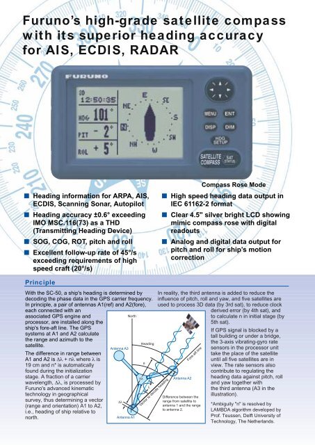
Compass Rose Mode<br />
■ High speed heading data output in<br />
IEC 61162-2 format<br />
■ Clear 4.5" silver bright LCD showing<br />
mimic compass rose with digital<br />
readouts<br />
■ Analog and digital data output for<br />
pitch and roll for ship’s motion<br />
correction<br />
Principle<br />
With the SC-50, a ship's heading is determined by<br />
decoding the phase data in the GPS carrier frequency.<br />
In principle, a pair of antennas A1(ref) and A2(fore),<br />
each connected with an<br />
associated GPS engine and<br />
North<br />
processor, are installed along the<br />
ship's fore-aft line. The GPS<br />
systems at A1 and A2 calculate<br />
the range and azimuth to the<br />
Heading<br />
satellite.<br />
Antenna A3<br />
The difference in range between<br />
A1 and A2 is ∆λ + nλ where λ is<br />
θ<br />
19 cm and n* is automatically<br />
found during the initialization<br />
stage. A fraction of a carrier<br />
nλ<br />
wavelength, ∆λ, is processed by<br />
λ<br />
<strong>Furuno</strong>'s advanced kinematic<br />
technology in geographical<br />
survey, thus determining a vector ∆λ<br />
(range and orientation) A1 to A2,<br />
i.e., heading of ship relative to<br />
north.<br />
Antenna A1<br />
Vector to decide heading<br />
In reality, the third antenna is added to reduce the<br />
influence of pitch, roll and yaw, and five satellites are<br />
used to process 3D data (by 3rd sat), to reduce clock<br />
derived error (by 4th sat), and<br />
to calculate n in initial stage (by<br />
5th sat).<br />
Antenna A2<br />
Fore-aft line<br />
Difference between the<br />
range from satellite to<br />
antenna 1 and the range<br />
to antenna 2.<br />
If GPS signal is blocked by a<br />
tall building or under a bridge,<br />
the 3-axis vibrating-gyro rate<br />
sensors in the processor unit<br />
take the place of the satellite<br />
until all five satellites are in<br />
view. The rate sensors also<br />
contribute to regulating the<br />
heading data against pitch, roll<br />
and yaw together with<br />
the third antenna (A3 in the<br />
illustration).<br />
*Ambiguity "n" is resolved by<br />
LAMBDA algorithm developed by<br />
Prof. Teussen, Delft University of<br />
Technology, The Netherlands.