PWM Method to Eliminate Power Sources in a Nonredundant 27 ...
PWM Method to Eliminate Power Sources in a Nonredundant 27 ...
PWM Method to Eliminate Power Sources in a Nonredundant 27 ...

Create successful ePaper yourself
Turn your PDF publications into a flip-book with our unique Google optimized e-Paper software.
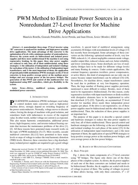
194 IEEE TRANSACTIONS ON INDUSTRIAL ELECTRONICS, VOL. 56, NO. 1, JANUARY 2009<br />
<strong>PWM</strong> <strong>Method</strong> <strong>to</strong> <strong>Elim<strong>in</strong>ate</strong> <strong>Power</strong> <strong>Sources</strong> <strong>in</strong> a<br />
<strong>Nonredundant</strong> <strong>27</strong>-Level Inverter for Mach<strong>in</strong>e<br />
Drive Applications<br />
Mauricio Rotella, Gonzalo Peñailillo, Javier Pereda, and Juan Dixon, Senior Member, IEEE<br />
Abstract—A nonredundant three-stage <strong>27</strong>-level <strong>in</strong>verter us<strong>in</strong>g<br />
“H” converters is analyzed for medium- and high-power mach<strong>in</strong>e<br />
drive applications. The ma<strong>in</strong> advantage of this converter is the<br />
optimization of levels with a m<strong>in</strong>imum number of semiconduc<strong>to</strong>rs.<br />
However, the system needs six bidirectional and isolated power<br />
supplies and three more unidirectional if the mach<strong>in</strong>e is not us<strong>in</strong>g<br />
regenerative brak<strong>in</strong>g. In this paper, these n<strong>in</strong>e power supplies<br />
are reduced <strong>to</strong> only four, all of them unidirectional, us<strong>in</strong>g three<br />
strategies: 1) the utilization of <strong>in</strong>dependent and isolated w<strong>in</strong>d<strong>in</strong>gs<br />
for each phase of the mo<strong>to</strong>r; 2) the utilization of <strong>in</strong>dependent <strong>in</strong>put<br />
transformers; and 3) the most important of them, the application<br />
of special pulsewidth modulation (<strong>PWM</strong>) strategies on the <strong>27</strong>-level<br />
converter, <strong>to</strong> keep positive average power at the medium power<br />
bridges and zero average power at the low-power bridges. The<br />
generation of this <strong>PWM</strong> and control of this multiconverter was<br />
implemented us<strong>in</strong>g DSP controllers, which give flexibility <strong>to</strong> the<br />
system.<br />
Index Terms—Drives, multilevel systems, pulsewidthmodulated<br />
power converters.<br />
I. INTRODUCTION<br />
PULSEWIDTH modulation (<strong>PWM</strong>) techniques used <strong>to</strong>day<br />
<strong>to</strong> control modern static converters such as high-power<br />
mach<strong>in</strong>e drives, strongly depend on switch<strong>in</strong>g frequency of<br />
the power semiconduc<strong>to</strong>rs. Normally, voltage moves <strong>to</strong> discrete<br />
values, forc<strong>in</strong>g the design of mach<strong>in</strong>es with good isolation, and<br />
sometimes loads with <strong>in</strong>ductances <strong>in</strong> excess of the required<br />
value. In other words, neither voltage nor current is as expected.<br />
This also means harmonic contam<strong>in</strong>ation, additional power<br />
losses, high-frequency noise, and <strong>in</strong>verter-<strong>in</strong>duced bear<strong>in</strong>g currents<br />
that <strong>in</strong>crease the ma<strong>in</strong>tenance problems of the drive [1],<br />
[2]. All these reasons have generated many research works on<br />
the <strong>to</strong>pic of <strong>PWM</strong> modulation [3]–[7]. More recently, cascade<br />
multilevel converters [8]–[12] have permitted <strong>to</strong> have many<br />
levels or steps of voltage <strong>to</strong> reduce the <strong>to</strong>tal harmonic dis<strong>to</strong>rtion<br />
(THD) levels. However, these converters have a big drawback:<br />
many isolated power supplies are required <strong>to</strong> get a good voltage<br />
Manuscript received Oc<strong>to</strong>ber 19, 2007; revised May <strong>27</strong>, 2008. First published<br />
November 18, 2008; current version published December 30, 2008. This<br />
work was supported <strong>in</strong> part by CONICYT under Project Fondecyt 1070751,<br />
<strong>in</strong> part by ABB Chile, and <strong>in</strong> part by Millenium Project P-04-048-F.<br />
M. Rotella is with ABB S.A., Santiago 7780006, Chile (e-mail: mauricio.<br />
rotella@cl.abb.com).<br />
G. Peñailillo, J. Pereda, and J. Dixon are with the Department of Electrical<br />
Eng<strong>in</strong>eer<strong>in</strong>g, Pontificia Universidad Católica de Chile, Santiago 7820436, Chile<br />
(e-mail: gepenail@uc.cl; jepereda@<strong>in</strong>g.puc.cl; jdixon@<strong>in</strong>g.puc.cl).<br />
Color versions of one or more of the figures <strong>in</strong> this paper are available onl<strong>in</strong>e<br />
at http://ieeexplore.ieee.org.<br />
Digital Object Identifier 10.1109/TIE.2008.9<strong>27</strong>233<br />
waveform. A special k<strong>in</strong>d of multilevel arrangement, us<strong>in</strong>g<br />
asymmetric H-bridges with nonredundant levels of voltage [13]<br />
has recently been <strong>in</strong>vestigated. Some advantages of these converters<br />
are the follow<strong>in</strong>g: optimized number of levels, very low<br />
THD, reduced dv/dt, almost negligible common-mode voltage,<br />
smaller output filter, reduced volume and cost, better reliability,<br />
and lower switch<strong>in</strong>g losses. Some drawbacks are loss of modularity<br />
(bridges have <strong>to</strong> be made for different voltage levels)<br />
and many float<strong>in</strong>g dc sources. Under certa<strong>in</strong> applications, like<br />
constant frequency operation (rectifiers, power compensa<strong>to</strong>rs,<br />
or active filters), this k<strong>in</strong>d of arrangement can use only one dc<br />
source because output transformers can be utilized [14]–[18].<br />
Nevertheless, for mach<strong>in</strong>e drives, output transformers cannot<br />
be used due <strong>to</strong> problems at very low-frequency operation.<br />
Then, the large number of float<strong>in</strong>g power supplies previously<br />
mentioned is more difficult <strong>to</strong> reduce. Besides, most of them<br />
need <strong>to</strong> be regenerative (bidirectional). For this reason, costly<br />
regenerative rectifiers with <strong>in</strong>put transformers or diode rectifiers<br />
with dissipative elements have <strong>to</strong> be implemented <strong>to</strong> solve<br />
that drawback [17]–[22]. Typically, an asymmetrical <strong>27</strong>-level<br />
<strong>in</strong>verter for mach<strong>in</strong>e drives needs three <strong>in</strong>dependent power<br />
supplies per phase. If the drive is not regenerative, six of these<br />
power supplies must be bidirectional and the other three can be<br />
unidirectional. Then, the reduction of these power supplies is<br />
an important fact.<br />
The purpose of this paper is <strong>to</strong> describe a special control<br />
and hardware strategies <strong>to</strong> reduce the n<strong>in</strong>e power supplies <strong>to</strong><br />
only four, all of them unidirectional. These special control and<br />
hardware strategies are the follow<strong>in</strong>g: a) the use of <strong>in</strong>dependent<br />
and isolated w<strong>in</strong>d<strong>in</strong>gs for each phase of the mo<strong>to</strong>r [23]; b) the<br />
utilization of <strong>in</strong>dependent <strong>in</strong>put transformers; and c) the most<br />
important of them, the application of special <strong>PWM</strong> strategies <strong>to</strong><br />
keep positive average power at the medium power bridges, and<br />
zero average power at the low-power bridges.<br />
II. BASICS OF MULTISTAGE CONVERTERS<br />
A. Basic Pr<strong>in</strong>ciple<br />
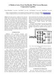
Fig. 1 shows the ma<strong>in</strong> components of a <strong>27</strong>-level converter<br />
us<strong>in</strong>g “H”-bridges. The figure only shows one of the three<br />
phases of the complete system. As shown, the dc power supplies<br />
of each one of the three converters are isolated and needs <strong>to</strong><br />
be bidirectional. Besides, the dc supplies are scaled with levels<br />
of voltage <strong>in</strong> power of three. The scal<strong>in</strong>g of voltages <strong>in</strong> power<br />
of three allows hav<strong>in</strong>g, with only three converters, 3 3 =<strong>27</strong><br />
0<strong>27</strong>8-0046/$25.00 © 2008 IEEE<br />
Authorized licensed use limited <strong>to</strong>: Pontificia University Ca<strong>to</strong>lica de Chile. Downloaded on January 8, 2009 at 15:13 from IEEE Xplore. Restrictions apply.
ROTELLA et al.: <strong>PWM</strong> METHOD TO ELIMINATE POWER SOURCES IN A NONREDUNDANT <strong>27</strong>-LEVEL INVERTER 195<br />
Fig. 1.<br />
Ma<strong>in</strong> components of the three-stage <strong>27</strong>-level drive (one phase).<br />
Fig. 3. Active power distribution <strong>in</strong> a three-stage converter (cos ϕ =1).<br />
Fig. 2.<br />
Voltage modulation <strong>in</strong> each converter for one complete cycle.<br />
different levels of voltage: 13 levels of positive values, 13 levels<br />
of negative values, and zero. The converter located at the<br />
<strong>to</strong>p of the figure has the biggest voltage, and will be called<br />
ma<strong>in</strong> converter. The other two modules will be the auxiliary<br />
converters. The ma<strong>in</strong> works at a lower switch<strong>in</strong>g frequency and<br />
carries more than 80% of the <strong>to</strong>tal power, which is an additional<br />
advantage of this <strong>to</strong>pology for high-power mach<strong>in</strong>e drives<br />
applications. Fig. 1 also shows the mach<strong>in</strong>e, with <strong>in</strong>dependent<br />
w<strong>in</strong>d<strong>in</strong>gs for each phase, <strong>to</strong> allow the utilization of only one<br />
power supply for the three ma<strong>in</strong> converters. With <strong>27</strong> levels<br />
of voltage, a three-stage converter can follow a s<strong>in</strong>usoidal<br />
waveform <strong>in</strong> a very precise way. It can control the load voltage<br />
as an amplitude modulation (AM) device. Fig. 2 shows the<br />
simulated voltage modulation <strong>in</strong> each one of the three “H”<br />
converters, for 100% AM.<br />
B. <strong>Power</strong> Distribution<br />
The example of Fig. 3 shows the simulated power distribution<br />
<strong>in</strong> one phase of the three-stage converter, feed<strong>in</strong>g a<br />
mach<strong>in</strong>e with cos ϕ =1(e.g., synchronous mach<strong>in</strong>e). A little<br />
more than 80% of the power is delivered by the ma<strong>in</strong> converters,<br />
about 15% for the Aux-1 converters, and less than 4% of the<br />
<strong>to</strong>tal power for Aux-2 converters. However, and despite Aux<br />
converters need low-power sources, they have <strong>to</strong> be bidirectional.<br />
There are three solutions for this problem: 1) active<br />
front-end rectifiers; 2) bidirectional dc–dc power supplies; or<br />
3) passive rectifiers with dissipative resis<strong>to</strong>rs. However, as the<br />
average negative power exists only at certa<strong>in</strong> levels of voltage,<br />
simple unidirectional rectifiers and special <strong>PWM</strong> modulation<br />
can be applied. This <strong>PWM</strong> modulation is based on jump<strong>in</strong>g<br />
some voltage levels when average power <strong>in</strong> a period becomes<br />
negative. This solution works well for both, Aux-1 and Aux-2<br />
converters. However, the <strong>to</strong>pology for the small Aux-2 converters<br />
can be simplified a little more us<strong>in</strong>g only an appropriate<br />
<strong>PWM</strong> technique.<br />
In the case of Aux-2, the power transfer is even smaller (less<br />
than 4%), and it can be managed <strong>to</strong> keep average power <strong>to</strong> zero<br />
by us<strong>in</strong>g high-capacity float<strong>in</strong>g capaci<strong>to</strong>rs and a special <strong>PWM</strong><br />
modulation, but keep<strong>in</strong>g THD as small as possible.<br />
III. INPUT POWER TOPOLOGY<br />
Us<strong>in</strong>g the aforementioned strategies, Fig. 4 shows the <strong>to</strong>pology<br />
of the complete power driver, <strong>in</strong>clud<strong>in</strong>g rectifiers and<br />
<strong>in</strong>verters. The H-bridges of the three ma<strong>in</strong> converters are fed<br />
<strong>in</strong> parallel from only one dc supply, with the transformer and<br />
rectifiers connected <strong>in</strong> series. The rectifiers are <strong>in</strong> six-pulse<br />
configuration with a four-w<strong>in</strong>d<strong>in</strong>g transformer, <strong>to</strong> create three<br />
secondary voltage systems, one for each of the three ma<strong>in</strong><br />
converters, and shifted <strong>in</strong> +20 ◦ ,0 ◦ , and −20 ◦ .<br />
This configuration generates a very low harmonic dis<strong>to</strong>rtion<br />
from the ma<strong>in</strong>’s po<strong>in</strong>t of view [11]. With this connection, the<br />
three w<strong>in</strong>d<strong>in</strong>gs of the mach<strong>in</strong>e have <strong>to</strong> be <strong>in</strong>dependently fed, as<br />
shown <strong>in</strong> Fig. 4. Otherwise, ma<strong>in</strong> bridges cannot <strong>in</strong>dependently<br />
work because they need <strong>to</strong> generate positive, negative, or zero<br />
voltage outputs at different times.<br />
As shown <strong>in</strong> Fig. 4, only four <strong>in</strong>dependent dc power supplies<br />
are required for the complete system <strong>in</strong>stead of n<strong>in</strong>e. Only one<br />
for the three ma<strong>in</strong> converters and three more (unidirectional<br />
low power) for Aux-1 converters. The Aux-2 converters only<br />
need float<strong>in</strong>g capaci<strong>to</strong>rs. As these two solutions need special<br />
modulation techniques <strong>to</strong> avoid power back at the Aux-1 and<br />
Authorized licensed use limited <strong>to</strong>: Pontificia University Ca<strong>to</strong>lica de Chile. Downloaded on January 8, 2009 at 15:13 from IEEE Xplore. Restrictions apply.
196 IEEE TRANSACTIONS ON INDUSTRIAL ELECTRONICS, VOL. 56, NO. 1, JANUARY 2009<br />
Fig. 4.<br />
Proposed <strong>to</strong>pology us<strong>in</strong>g only four float<strong>in</strong>g power supplies.<br />
<strong>to</strong> keep zero average power at Aux-2, the next sections will<br />
expla<strong>in</strong> the modulation techniques implemented <strong>in</strong> this paper.<br />
IV. MODULATION TECHNIQUES IMPLEMENTED<br />
Although high-quality output of multistage converters have<br />
been known for quite a while, the large part count, quantity<br />
of isolated sources, and overall system complexity have limited<br />
their use <strong>in</strong> many potential applications. Topologies with<br />
fewer components are <strong>in</strong>herently more reliable. In this section,<br />
three enhancements will be expla<strong>in</strong>ed. The first one is the<br />
<strong>PWM</strong> applied <strong>to</strong> each possible level. This enhancement was<br />
absolutely necessary <strong>to</strong> develop the next two. The second one<br />
is a control strategy <strong>to</strong> have zero average current over Aux-2,<br />
which enables the replacement of the bidirectional sources with<br />
float<strong>in</strong>g capaci<strong>to</strong>rs. F<strong>in</strong>ally, an additional improvement <strong>in</strong> the<br />
control scheme will be presented, which elim<strong>in</strong>ates the need<br />
for bidirectional sources on stage Aux-1, by keep<strong>in</strong>g positive<br />
average current <strong>in</strong> all operat<strong>in</strong>g conditions.<br />
A. <strong>PWM</strong> <strong>to</strong> Each Level<br />
With three stages per phase scaled <strong>in</strong> power of three, <strong>27</strong><br />
unique levels <strong>in</strong> the output voltage waveform can be generated.<br />
This amount of levels assures high-quality voltage and current<br />
waveforms for full converter voltage. When lower voltages are<br />
required at the output, for lower output frequencies <strong>in</strong> a mach<strong>in</strong>e<br />
drive for example, the voltage steps become larger compared<br />
<strong>to</strong> peak voltage amplitude. When this happens, the current<br />
harmonics <strong>to</strong> the mo<strong>to</strong>r tend <strong>to</strong> be more relevant, <strong>in</strong>crement<strong>in</strong>g<br />
mo<strong>to</strong>r losses, audible noise, and risk of pulsat<strong>in</strong>g <strong>to</strong>rques.<br />
One way <strong>to</strong> overcome this limitation is <strong>to</strong> <strong>in</strong>troduce <strong>PWM</strong> <strong>to</strong><br />
each level. The benefits are more significant for lower output<br />
voltages. The disadvantage is higher switch<strong>in</strong>g frequency <strong>in</strong> all<br />
semiconduc<strong>to</strong>rs but particularly <strong>in</strong> auxiliary stages. The ma<strong>in</strong><br />
stage needs <strong>to</strong> be commutated <strong>in</strong> very few levels, so the average<br />
switch<strong>in</strong>g frequency for this level can be kept low.<br />
B. Zero Average <strong>Power</strong> at Aux-2<br />
The advantage of nonredundant multilevel <strong>in</strong>verter is that<br />
large quantity of level can be achieved at the output voltage with<br />
extremely low harmonic current. The biggest drawback is that<br />
for some levels, the dc current over a stage can become negative<br />
(negative power). If the average dc current for complete cycle <strong>in</strong><br />
a particular state of operation (voltage and frequency) is negative,<br />
then is necessary <strong>to</strong> have a bidirectional dc–dc converter <strong>to</strong><br />
withdraw the energy from the capaci<strong>to</strong>r <strong>to</strong> the feed<strong>in</strong>g network.<br />
This requirement adds complexity <strong>to</strong> the system. The previous<br />
Fig. 3 showed, for all three stages (ma<strong>in</strong>, Aux-1, and Aux-2),<br />
the active power <strong>in</strong> each converter from 0% <strong>to</strong> 100% voltage<br />
(levels 0 <strong>to</strong> 13). From this figure, it is shown that depend<strong>in</strong>g on<br />
the <strong>in</strong>verter operat<strong>in</strong>g conditions, auxiliary stages can have either<br />
positive or negative power. For the particular case of Aux-2,<br />
which manages less than 4% of the <strong>to</strong>tal power, the need of a<br />
power sources can be elim<strong>in</strong>ated by br<strong>in</strong>g<strong>in</strong>g this average dc<br />
current, thus power, <strong>to</strong> zero.<br />
As shown <strong>in</strong> Table I, the effect of the pulse is different for<br />
every level. For example, from level +5 <strong>to</strong>+6, the dc current<br />
over Aux-2 (power) is go<strong>in</strong>g from negative (charg<strong>in</strong>g) at base,<br />
<strong>to</strong> zero dur<strong>in</strong>g the pulse. At the next output level of +7, the<br />
effect of the pulse is completely opposite go<strong>in</strong>g from zero<br />
current at the base and positive current dur<strong>in</strong>g the pulse, as also<br />
shown <strong>in</strong> Fig. 3. This alternat<strong>in</strong>g pulse effect makes possible<br />
zero average current over Aux-2 and elim<strong>in</strong>ation of the source<br />
by controll<strong>in</strong>g the capaci<strong>to</strong>r voltage. The control block <strong>in</strong> Fig. 5<br />
controls the dc voltage by adjust<strong>in</strong>g the width of the pulses<br />
proportional <strong>to</strong> voltage error and the pulse effect <strong>in</strong> a particular<br />
output level. In the example of Fig. 6, if the voltage over the<br />
capaci<strong>to</strong>r is lower than the reference, the dc voltage controller<br />
will decrease the width of the pulses on level +6 and <strong>in</strong>crease<br />
them for level +7.<br />
The additional current harmonics with this control strategy<br />
can be neglected for most of cases. For low output voltages, at<br />
least two stages have <strong>to</strong> be <strong>in</strong> operation <strong>to</strong> keep the average<br />
current zero. Dur<strong>in</strong>g the evolution of the voltage waveform,<br />
the dc voltage controller will adjust the standard <strong>PWM</strong> pattern<br />
<strong>in</strong> a way that the capaci<strong>to</strong>r voltage is kept constant as shown<br />
<strong>in</strong> simulation of Fig. 7. The bigger the capacitance, the lower<br />
the ripple. Large capacitance can assure that only very small<br />
deviation <strong>to</strong> the optimum <strong>PWM</strong> is necessary, keep<strong>in</strong>g the current<br />
harmonics <strong>to</strong> the m<strong>in</strong>imum. However, the capaci<strong>to</strong>r cannot<br />
be <strong>in</strong>def<strong>in</strong>itely enlarged and, if the converter is work<strong>in</strong>g at the<br />
smallest voltage (level 1 or 1/13 of full voltage for long time),<br />
the capaci<strong>to</strong>r f<strong>in</strong>ally will not be able <strong>to</strong> keep constant voltage<br />
(will discharge). This problem represents a drawback of the<br />
system, but it has a solution. It can go <strong>to</strong> level 2 and keep<br />
the required voltage us<strong>in</strong>g <strong>PWM</strong>. This last attribute was not<br />
implemented but is only a matter of additional software.<br />
C. Positive Average <strong>Power</strong> at Aux-1<br />
Also, <strong>in</strong> Aux-1 stage, there is need for bidirectional dc source<br />
for some operat<strong>in</strong>g conditions, due <strong>to</strong> the negative average<br />
current. In Fig. 3, this area starts from level 5 <strong>to</strong> level 7.<br />
Then aga<strong>in</strong>, as done for Aux-2, the overall <strong>to</strong>pology can<br />
Authorized licensed use limited <strong>to</strong>: Pontificia University Ca<strong>to</strong>lica de Chile. Downloaded on January 8, 2009 at 15:13 from IEEE Xplore. Restrictions apply.
ROTELLA et al.: <strong>PWM</strong> METHOD TO ELIMINATE POWER SOURCES IN A NONREDUNDANT <strong>27</strong>-LEVEL INVERTER 197<br />
TABLE I<br />
EFFECT OF A PULSE FOR EACH LEVEL,OVER POSITIVE VOLTAGE (HALF CYCLE)<br />
Fig. 5.<br />
Aux-2 float<strong>in</strong>g capaci<strong>to</strong>rs voltage control.<br />
Fig. 7. Twenty-seven level output voltage, current, and dc voltage over Aux-2<br />
float<strong>in</strong>g capaci<strong>to</strong>r.<br />
TABLE II<br />
FORBIDDEN LEVELS OF OPERATION (WHEN dc CURRENT IS<br />
REGENERATIVE)OVER AUX-1, AS A FUNCTION OF<br />
OUTPUT CURRENT I O<br />
Fig. 6. Effect of a voltage pulse over Aux-2 current (I Aux 2) dur<strong>in</strong>g levels<br />
+6and+7.<br />
be simplified by <strong>in</strong>hibit<strong>in</strong>g negative average currents <strong>in</strong> this<br />
stage. The strategy consists on identify<strong>in</strong>g the levels where the<br />
dc current becomes negative and jump<strong>in</strong>g on <strong>to</strong> the next positive<br />
current level. The simulation has shown that very low additional<br />
current harmonics are generated <strong>to</strong> the mo<strong>to</strong>r. Table II <strong>in</strong>dicates<br />
<strong>in</strong>hibited levels or jumps, which depend on Aux-1 voltage sign<br />
(+1, 0, or −1) and the direction of the output ac current Io.<br />
For example, for positive voltage (Vo) and current (Io), the<br />
jump goes from level +4 <strong>to</strong>+8. <strong>PWM</strong> is done between these<br />
Authorized licensed use limited <strong>to</strong>: Pontificia University Ca<strong>to</strong>lica de Chile. Downloaded on January 8, 2009 at 15:13 from IEEE Xplore. Restrictions apply.
198 IEEE TRANSACTIONS ON INDUSTRIAL ELECTRONICS, VOL. 56, NO. 1, JANUARY 2009<br />
Fig. 9. Voltage and current at the mo<strong>to</strong>r w<strong>in</strong>d<strong>in</strong>gs. (a) Three phase at nom<strong>in</strong>al<br />
conditions. (b) S<strong>in</strong>gle phase dur<strong>in</strong>g an acceleration from zero <strong>to</strong> nom<strong>in</strong>al<br />
operat<strong>in</strong>g conditions.<br />
Fig. 8. Control enhancement <strong>to</strong> <strong>in</strong>hibit negative mean current. (a) Voltage and<br />
current (THD =0.21%) without INC function. (b) Aux-1 current and negative<br />
average value. (c) Voltage and current (THD =0.32%) with INC function<br />
active. (d) Aux-1 current and positive average value.<br />
two levels <strong>to</strong> m<strong>in</strong>imize the output current harmonics. Because<br />
of symmetry <strong>in</strong> Table II, negative levels are not displayed.<br />
The 19 level voltage of Fig. 8(a) and (b) (70% amplitude <strong>in</strong><br />
<strong>27</strong>-level <strong>in</strong>verter), under normal conditions, requires a negative<br />
mean current for Aux-1. This energy can either be regenerated<br />
back <strong>to</strong> the network through a dc–dc bidirectional converter<br />
or dissipated <strong>in</strong> a resistance with a chopper. The disadvantage<br />
of both of these options is that they require additional hardware<br />
and complexity. Besides, the resis<strong>to</strong>r–chopper comb<strong>in</strong>ation<br />
is quite <strong>in</strong>efficient. Fig. 8(c) shows the modified output<br />
voltage with activated <strong>in</strong>hibit negative current (INC) function,<br />
which ma<strong>in</strong>ta<strong>in</strong>s the mean Aux-1 current positive as shown <strong>in</strong><br />
Fig. 8(d). The solution ma<strong>in</strong>ta<strong>in</strong>s a negligible current dis<strong>to</strong>rtion<br />
(THD =0.32%) with the proposed control strategy.<br />
V. S IMULATED WAVEFORMS<br />
The follow<strong>in</strong>g (and also the previous) simulations were performed<br />
us<strong>in</strong>g PSIM, a special simula<strong>to</strong>r for power electronics<br />
circuits [24]. Fig. 9 shows the three-phase output voltages<br />
and currents produced by the three-stage converter at nom<strong>in</strong>al<br />
conditions and dur<strong>in</strong>g a acceleration from 0 Hz–0 V <strong>to</strong> 50 Hz–<br />
2300 V. The mach<strong>in</strong>e is a 2-MW 2.3-kV 594-A 50-Hz <strong>in</strong>duction<br />
Fig. 10. Current harmonics spectrum at the mo<strong>to</strong>r w<strong>in</strong>d<strong>in</strong>gs at 70% of the<br />
voltage amplitude (19 levels). (a) Without INC function activated and negative<br />
mean current over Aux-1. (b) With INC function activated and positive mean<br />
current over Aux-1. Note the scale of these diagrams.<br />
mo<strong>to</strong>r with <strong>in</strong>dependent and isolated w<strong>in</strong>d<strong>in</strong>gs as shown <strong>in</strong><br />
Fig. 3. Fig. 10 shows current harmonic dis<strong>to</strong>rtion with and<br />
without INC function.<br />
F<strong>in</strong>ally, Fig. 11 shows current and voltage waveforms without<br />
and with INC function at 35% of full voltage.<br />
VI. EXPERIMENTAL RESULTS<br />
For experiments, a small-scale 3-kW <strong>27</strong>-level <strong>in</strong>verter us<strong>in</strong>g<br />
H-bridge <strong>in</strong>sulated gate bipolar transis<strong>to</strong>r modules was implemented.<br />
The three ma<strong>in</strong> bridges were connected <strong>to</strong> a common<br />
72-Vdc power supply, and the Aux-1 converters were fed<br />
with three <strong>in</strong>dependent 24-Vdc unidirectional power supplies.<br />
F<strong>in</strong>ally, the Aux-2 converters were implemented with float<strong>in</strong>g<br />
ultracapaci<strong>to</strong>rs and a feedback control loop that ma<strong>in</strong>ta<strong>in</strong>s their<br />
dc voltages at 8 Vdc. These ultracapaci<strong>to</strong>rs do not need <strong>to</strong> be<br />
Authorized licensed use limited <strong>to</strong>: Pontificia University Ca<strong>to</strong>lica de Chile. Downloaded on January 8, 2009 at 15:13 from IEEE Xplore. Restrictions apply.
ROTELLA et al.: <strong>PWM</strong> METHOD TO ELIMINATE POWER SOURCES IN A NONREDUNDANT <strong>27</strong>-LEVEL INVERTER 199<br />
Fig. 11. S<strong>in</strong>gle-phase voltage and current waveforms <strong>in</strong> one of the mo<strong>to</strong>r<br />
w<strong>in</strong>d<strong>in</strong>gs. (a) Without and (b) with INC function at 35% of full voltage.<br />
Fig. 13. Waveforms with INC function at 80% full voltage. (a) Three-phase<br />
voltage waveforms. (b) S<strong>in</strong>gle-phase voltage and current, and dc current from<br />
Aux-1 supply (average current positive).<br />
Fig. 14.<br />
Step change from 20 <strong>to</strong> 60 Hz.<br />
Fig. 12. Experimental oscillograms without INC function (100% voltage).<br />
(a) Three-phase voltage waveform. (b) S<strong>in</strong>gle phase voltage and current.<br />
larger than 1 F, but 23-F devices were used because of lack<br />
of smaller capaci<strong>to</strong>rs. The load was a 1-kW 230-V <strong>in</strong>duction<br />
mach<strong>in</strong>e with <strong>in</strong>dependent w<strong>in</strong>d<strong>in</strong>gs for each phase, as was<br />
required for the implementation of this <strong>to</strong>pology (see Fig. 4).<br />
Fig. 12(a) shows the voltage waveforms of each one of the<br />
three phases under normal operation (no jump<strong>in</strong>g levels or<br />
steps). On the other hand, Fig. 12(b) shows the voltage and<br />
current <strong>in</strong> one of the phases of the <strong>in</strong>verter. It can be observed<br />
that the quality of the current is very high as expected with a<br />
<strong>27</strong>-level <strong>in</strong>verter. Now, Fig. 13(a) shows the <strong>in</strong>verter waveforms<br />
when the INC function has been activated because the average<br />
power <strong>in</strong> the Aux-1 supply becomes negative when this function<br />
is not applied. The “jump<strong>in</strong>gs” on the voltage steps are clearly<br />
present <strong>in</strong> the figure, and the current is not seriously affected.<br />
The oscillogram without negative parts is the dc l<strong>in</strong>k current,<br />
which is be<strong>in</strong>g controlled <strong>to</strong> keep positive average power at<br />
the dc l<strong>in</strong>k. Similarly, Fig. 13(b) shows the three-phase voltage<br />
Fig. 15.<br />
Step change from zero <strong>to</strong> full load.<br />
waveforms and the jump<strong>in</strong>g of voltage steps <strong>to</strong> keep <strong>in</strong> each<br />
one of the three Aux-1 converters, the required positive average<br />
power at the dc l<strong>in</strong>k. To simplify the comparison with Fig. 12,<br />
this figure has been done at the same frequency (50 Hz).<br />
Fig. 14 shows a step response of the system from 20 <strong>to</strong> 60 Hz,<br />
and Fig. 15 shows a step response of the system from zero<br />
load <strong>to</strong> full load. As can be appreciated, the power converter<br />
can manage transient situations keep<strong>in</strong>g the current with low<br />
harmonic dis<strong>to</strong>rtion.<br />
Authorized licensed use limited <strong>to</strong>: Pontificia University Ca<strong>to</strong>lica de Chile. Downloaded on January 8, 2009 at 15:13 from IEEE Xplore. Restrictions apply.
200 IEEE TRANSACTIONS ON INDUSTRIAL ELECTRONICS, VOL. 56, NO. 1, JANUARY 2009<br />
VII. CONCLUSION<br />
A comb<strong>in</strong>ation of <strong>to</strong>pological solutions and special control<br />
strategies, <strong>to</strong> reduce and simplify power sources <strong>in</strong> a <strong>27</strong>-level<br />
<strong>in</strong>verter for mach<strong>in</strong>e drive applications, has been <strong>in</strong>vestigated.<br />
Normally, these converters need six bidirectional, float<strong>in</strong>g<br />
power supplies, and three more unidirectional if the mach<strong>in</strong>e is<br />
not us<strong>in</strong>g regenerative brak<strong>in</strong>g. In this paper, these n<strong>in</strong>e power<br />
supplies are reduced <strong>to</strong> only four, all of them unidirectional.<br />
The circuit connections and control strategies utilized were:<br />
1) the application of <strong>in</strong>dependent and isolated w<strong>in</strong>d<strong>in</strong>gs for<br />
each phase of the mo<strong>to</strong>r, which allows the utilization of only<br />
one power supply for the ma<strong>in</strong> bridges; 2) the utilization of<br />
<strong>in</strong>dependent <strong>in</strong>put transformers; and 3) the most significant of<br />
them, the generation of special <strong>PWM</strong> strategies <strong>to</strong> keep positive<br />
average power at the medium power converters (Aux-1),<br />
and zero average power at the low-power converters (Aux-2).<br />
Simulations have shown excellent results, with only a little<br />
<strong>in</strong>crement <strong>in</strong> harmonic dis<strong>to</strong>rtion compared with the system<br />
with n<strong>in</strong>e <strong>in</strong>dependent power supplies. The experiments <strong>in</strong> a<br />
3-kW pro<strong>to</strong>type show similar results <strong>to</strong> the ones obta<strong>in</strong>ed <strong>in</strong><br />
simulations.<br />
REFERENCES<br />
[1] A. Muetze and A. B<strong>in</strong>der, “Calculation of circulat<strong>in</strong>g bear<strong>in</strong>g currents <strong>in</strong><br />
mach<strong>in</strong>es of <strong>in</strong>verter-based drive systems,” IEEE Trans. Ind. Electron.,<br />
vol. 54, no. 2, pp. 932–938, Apr. 2007.<br />
[2] A. Muetze and A. B<strong>in</strong>der, “Practical rules for assessment of <strong>in</strong>verter<strong>in</strong>duced<br />
bear<strong>in</strong>g currents <strong>in</strong> <strong>in</strong>verter-fed AC mo<strong>to</strong>rs up <strong>to</strong> 500 kW,” IEEE<br />
Trans. Ind. Electron., vol. 54, no. 3, pp. 1614–1622, Jun. 2007.<br />
[3] K. M. Cho, W. S. Oh, Y. T. Kim, and H. J. Kim, “A new switch<strong>in</strong>g strategy<br />
for pulse width modulation (<strong>PWM</strong>) power converter,” IEEE Trans. Ind.<br />
Electron., vol. 54, no. 1, pp. 330–337, Feb. 2007.<br />
[4] J. Rodríguez, S. Bernet, B. Wu, J. O. Pontt, and S. Kouro, “Multilevel<br />
voltage-source-converter <strong>to</strong>pologies for <strong>in</strong>dustrial medium-voltage<br />
drives,” IEEE Trans. Ind. Electron., vol. 54, no. 6, pp. 2930–2945,<br />
Dec. 2007.<br />
[5] D. Chung, J. Kim, and S. Sul, “Unified voltage modulation technique for<br />
real time three-phase power conversion,” IEEE Trans. Ind. Appl., vol. 34,<br />
no. 2, pp. 374–380, Mar./Apr. 1998.<br />
[6] J. Holtz and B. Beyer, “Fast current trajec<strong>to</strong>ry track<strong>in</strong>g control based on<br />
synchronous optimal pulse width modulation,” IEEE Trans. Ind. Appl.,<br />
vol. 31, no. 5, pp. 1110–1120, Sep./Oct. 1995.<br />
[7] S. Kouro, J. Rebolledo, and J. Rodriguez, “Reduced switch<strong>in</strong>g-frequencymodulation<br />
algorithm for high-power multilevel <strong>in</strong>verters,” IEEE Trans.<br />
Ind. Electron., vol. 54, no. 4, pp. 2894–2901, Aug. 2007.<br />
[8] J. R. Rodriguez, J. W. Dixon, J. R. Esp<strong>in</strong>oza, J. Pontt, and P. Lezana,<br />
“<strong>PWM</strong> regenerative rectifiers: State of the art,” IEEE Trans. Ind. Electron.,<br />
vol. 52, no. 1, pp. 5–22, Feb. 2005.<br />
[9] A. Draou, M. Benghanen, and A. Tahri, “Multilevel converters and<br />
VAR compensation,” <strong>in</strong> <strong>Power</strong> Electronics Handbook, M.H.Rashid,Ed.<br />
New York: Academic, 2001, ch. 25, pp. 615–622.<br />
[10] F. Zheng Peng, “A generalized multilevel <strong>in</strong>verter <strong>to</strong>pology with self<br />
voltage balanc<strong>in</strong>g,” IEEE Trans. Ind. Appl., vol. 37, no. 2, pp. 611–618,<br />
Mar./Apr. 2001.<br />
[11] K. Matsui, Y. Kawata, and F. Ueda, “Application of parallel<br />
connected NPC-<strong>PWM</strong> <strong>in</strong>verters with multilevel modulation for AC mo<strong>to</strong>r<br />
drive,” IEEE Trans. <strong>Power</strong> Electron., vol. 15, no. 5, pp. 901–907,<br />
Sep. 2000.<br />
[12] C. Rech and J. R. P<strong>in</strong>heiro, “Hybrid multilevel converters: Unified analysis<br />
and design considerations,” IEEE Trans. Ind. Electron., vol. 54, no. 2,<br />
pp. 1092–1104, Apr. 2007.<br />
[13] J. Dixon and L. Morán, “Multilevel <strong>in</strong>verter, based on multi-stage connection<br />
of three-level converters, scaled <strong>in</strong> power of three,” <strong>in</strong> Proc. IEEE<br />
IECON, Seville, Spa<strong>in</strong>, Nov. 5–8, 2002, pp. 886–891.<br />
[14] J. Dixon and L. Moran, “A clean four-quadrant s<strong>in</strong>usoidal power rectifier<br />
us<strong>in</strong>g multistage converters for subway applications,” IEEE Trans. Ind.<br />
Electron., vol. 52, no. 3, pp. 653–661, Jun. 2005.<br />
[15] F.-S. Kang, S.-J. Park, M. H. Lee, and C.-U. Kim, “An efficient multilevelsynthesis<br />
approach and its application <strong>to</strong> a <strong>27</strong>-level <strong>in</strong>verter,” IEEE Trans.<br />
Ind. Electron., vol. 52, no. 6, pp. 1600–1606, Dec. 2005.<br />
[16] M. E. Ortuzar, R. E. Carmi, J. W. Dixon, and L. Moran, “Voltage-source<br />
active power filter based on multilevel converter and ultracapaci<strong>to</strong>r DC<br />
l<strong>in</strong>k,” IEEE Trans. Ind. Electron., vol. 53, no. 2, pp. 477–485, Apr. 2006.<br />
[17] O. Gaupp, P. Zan<strong>in</strong>i, P. Daehler, E. Baerlocher, R. Boeck, and<br />
J. Wern<strong>in</strong>ger, “Bremen’s 100 MW static frequency l<strong>in</strong>k,” ABB Rev., pp. 4–<br />
17, Oct. 1996.<br />
[18] M. Carpita, M. Marchesoni, M. Peller<strong>in</strong>, and D. Moser, “Multilevel converter<br />
for traction applications: Small-scale pro<strong>to</strong>type tests results,” IEEE<br />
Trans. Ind. Electron., vol. 55, no. 5, pp. 2203–2212, May 2008.<br />
[19] M. A. Perez, J. R. Esp<strong>in</strong>oza, J. R. Rodriguez, and P. Lezana, “Regenerative<br />
medium-voltage AC drive based on a multicell arrangement with reduced<br />
energy s<strong>to</strong>rage requirements,” IEEE Trans. Ind. Electron., vol. 52, no. 1,<br />
pp. 171–180, Feb. 2005.<br />
[20] J. Dixon, A. Bretón, F. Ríos, and L. Morán, “High power mach<strong>in</strong>e drive,<br />
based on three-stage connection of ‘H’ converters, and active front end<br />
rectifiers,” <strong>in</strong> Proc. IEEE IECON, Roanoke, VA, Nov. 2–6, 2003, pp. 226–<br />
231. CD-ROM.<br />
[21] P. Lezana, J. Rodriguez, and D. A. Oyarzun, “Cascaded multilevel <strong>in</strong>verter<br />
with regeneration capability and reduced number of switches,” IEEE<br />
Trans. Ind. Electron., vol. 55, no. 3, pp. 1059–1066, Jun. 2008.<br />
[22] P. Lezana, C. A. Silva, J. Rodríguez, and M. A. Pérez, “Zero-steady-stateerror<br />
<strong>in</strong>put-current controller for regenerative multilevel converters based<br />
on s<strong>in</strong>gle-phase cells,” IEEE Trans. Ind. Electron., vol. 54, no. 2, pp. 733–<br />
740, Apr. 2007.<br />
[23] V. T. Somasekhar, K. Gopakumar, M. R. Baiju, K. K. Mohapatra, and<br />
L. Umanand, “A multilevel <strong>in</strong>verter system for an <strong>in</strong>duction mo<strong>to</strong>r with<br />
open-end w<strong>in</strong>d<strong>in</strong>gs,” IEEE Trans. Ind. Electron., vol. 52, no. 3, pp. 824–<br />
836, Jun. 2005.<br />
[24] “PSIM version 4.1,” <strong>Power</strong> Electronics Simulations, User Manual,<br />
Vancouver, BC, Canada: <strong>Power</strong>sim Technol. [Onl<strong>in</strong>e]. Available: http://<br />
www.powersimtech.com<br />
Mauricio Rotella received the Electrical Eng<strong>in</strong>eer<br />
Professional and the Master of Science degrees from<br />
Pontificia Universidad Católica de Chile, Santiago,<br />
Chile, <strong>in</strong> 1999 and 2006, respectively.<br />
S<strong>in</strong>ce 1998, he has been with ABB S.A.,<br />
Santiago, <strong>in</strong> various positions, <strong>in</strong>clud<strong>in</strong>g Product<br />
Manager for large drives for ABB Chile and Regional<br />
Sales Manager for Lat<strong>in</strong> America MV Drives<br />
for ABB Switzerland. Currently, he is with the Au<strong>to</strong>mation<br />
Products Local Division for ABB Chile.<br />
Gonzalo Peñailillo was born <strong>in</strong> Santiago, Chile, <strong>in</strong><br />
1983. He received the Civil Electrical Eng<strong>in</strong>eer and<br />
the Master of Science (with dist<strong>in</strong>guish evaluation)<br />
degrees from the Pontificia Universidad Católica de<br />
Chile, Santiago, <strong>in</strong> 2007.<br />
He is with the Department of Electrical Eng<strong>in</strong>eer<strong>in</strong>g,<br />
Pontificia Universidad Católica de Chile.<br />
His studies have been focused on au<strong>to</strong>matic control<br />
and power electronics. He has participated <strong>in</strong> several<br />
university competitions related <strong>to</strong> electrical eng<strong>in</strong>eer<strong>in</strong>g,<br />
stand<strong>in</strong>g out <strong>in</strong> the Small Robots (Microbot)<br />
Competition (First Place, 2006) and <strong>in</strong> the Electric Car Competition Formula-I<br />
(Fourth Place and Best Design).<br />
Authorized licensed use limited <strong>to</strong>: Pontificia University Ca<strong>to</strong>lica de Chile. Downloaded on January 8, 2009 at 15:13 from IEEE Xplore. Restrictions apply.
ROTELLA et al.: <strong>PWM</strong> METHOD TO ELIMINATE POWER SOURCES IN A NONREDUNDANT <strong>27</strong>-LEVEL INVERTER 201<br />
Javier Pereda was born <strong>in</strong> Santiago, Chile, <strong>in</strong> 1983.<br />
He is currently work<strong>in</strong>g <strong>to</strong>ward the M.Sc. degree <strong>in</strong><br />
electrical eng<strong>in</strong>eer<strong>in</strong>g at the Pontificia Universidad<br />
Católica de Chile (PUC), Santiago.<br />
He is a Research Assistant <strong>in</strong> power electronics,<br />
electrical mach<strong>in</strong>es, and power generation with<br />
the Department of Electrical Eng<strong>in</strong>eer<strong>in</strong>g, PUC. His<br />
ma<strong>in</strong> research <strong>in</strong>terests <strong>in</strong>clude au<strong>to</strong>matic control and<br />
power electronics, specifically ac drives. He is currently<br />
work<strong>in</strong>g on direct <strong>to</strong>rque control <strong>in</strong> multilevel<br />
<strong>in</strong>verters us<strong>in</strong>g an ABB <strong>in</strong>dustrial controller.<br />
Mr. Pereda is a member of the Núcleo Electrónica Industrial y Mecatrónica<br />
(NEIM), Chile.<br />
Juan Dixon (M’90–SM’95) was born <strong>in</strong> Santiago,<br />
Chile. He received the degree <strong>in</strong> electrical eng<strong>in</strong>eer<strong>in</strong>g<br />
from the Universidad de Chile, Santiago,<br />
<strong>in</strong> 1977, and the M.Eng. and Ph.D. degrees from<br />
McGill University, Montreal, QC, Canada, <strong>in</strong> 1986,<br />
and 1988, respectively.<br />
In 1976, he was work<strong>in</strong>g with the State Transportation<br />
Company <strong>in</strong> charge of trolleybuses operation.<br />
In 1977 and 1978, he was with the Chilean<br />
Railways Company. S<strong>in</strong>ce 1979, he has been with<br />
the Department of Electrical Eng<strong>in</strong>eer<strong>in</strong>g, Pontificia<br />
Universidad Católica de Chile, Santiago, where he is currently a Professor.<br />
He has presented more than 70 works at <strong>in</strong>ternational conferences and<br />
has published more than 30 papers related <strong>to</strong> power electronics <strong>in</strong> IEEE<br />
TRANSACTIONS and IEE Proceed<strong>in</strong>gs. His ma<strong>in</strong> areas of <strong>in</strong>terest are <strong>in</strong> electric<br />
traction, power converters, pulsewidth modulation rectifiers, active power<br />
filters, power fac<strong>to</strong>r compensa<strong>to</strong>rs, and multilevel and multistage converters.<br />
He has performed consult<strong>in</strong>g work related <strong>to</strong> trolleybuses, traction substations,<br />
mach<strong>in</strong>e drives, hybrid electric vehicles, and electric railways. He has created<br />
an electric vehicle labora<strong>to</strong>ry, where he has built state-of-the-art vehicles us<strong>in</strong>g<br />
brushless dc mach<strong>in</strong>es with ultracapaci<strong>to</strong>rs and high-specific-energy batteries.<br />
Authorized licensed use limited <strong>to</strong>: Pontificia University Ca<strong>to</strong>lica de Chile. Downloaded on January 8, 2009 at 15:13 from IEEE Xplore. Restrictions apply.