ZINC OXIDE VARISTORS Introduction
ZINC OXIDE VARISTORS Introduction
ZINC OXIDE VARISTORS Introduction

You also want an ePaper? Increase the reach of your titles
YUMPU automatically turns print PDFs into web optimized ePapers that Google loves.
Zinc Oxide Varistors<br />
<strong>Introduction</strong><br />
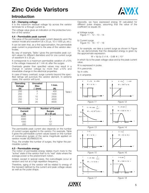
4.3 - Clamping voltage<br />
It is the maximum residual voltage Vp across the varistor<br />
terminals for a through current Ip.<br />
The voltage value gives an indication on the protective function<br />
of the varistor.<br />
4.4 - Permissible peak current<br />
The value of the permissible peak current depends upon the<br />
varistor model and waveform (8 x 20 µs, 10 x 1000 µs, etc.).<br />
It can be seen that, as a first approximation, the permissible<br />
peak current is proportional to the area of the varistor electrodes.<br />
By way of example, Table I gives the permissible peak current<br />
values for different diameters and for one current surge<br />
of waveform 8 x 20 µs.<br />
It corresponds to a maximum permissible variation of ±10%<br />
in the voltage measured at 1 mA dc after the surges.<br />
Overloads greater than specified values may result in a<br />
change in varistor voltage by more than ±10% and<br />
irreversible change in the electrical properties.<br />
In case of heavy overload, surge currents beyond the specified<br />
ratings will puncture the varistor element. In extreme<br />
cases, the varistor will burst.<br />
Operating Uncoated<br />
Voltage<br />
Disc<br />
I max.<br />
(V) (mm) (A)<br />
250 5 400<br />
250 7 1200<br />
250 10 2500<br />
250 14 4500<br />
250 20 6500<br />
Table I<br />
The permissible peak current also depends on the number<br />
of current surges applied to the varistor. For example, Table<br />
II gives the permissible current values based on the number<br />
of consecutive surges of the same magnitude applied on<br />
varistor model VE24M00251K.<br />
Thus, the smaller the number of surges, the higher the permissible<br />
current.<br />
4.5 - Permissible energy<br />
The notion of permissible energy relates much more to the<br />
“active” state of the varistor than to its “rest” state where the<br />
average power is the predominant notion.<br />
Indeed, except in special cases, the overvoltages occur at<br />
random and not at a high repetition frequency.<br />
Therefore, aging of the varistor will be related to energy of<br />
the transient defined by the current and peak voltage values<br />
as well as the pulse shape.<br />
Opposite, we have expressed energy W calculated for<br />
different pulse shapes, assuming that the value of the<br />
coefficient equals 30.<br />
a<br />
a) Voltage surge<br />
Figure 11 - 12 - 13 - 14<br />
b) Current surge<br />
Figure 15 - 16 - 17 - 18<br />
If, for example, we take a current surge as shown in Figure<br />
19, we demonstrate that the dissipated energy is given by<br />
the approximate expression:<br />
W = Vp Ip (1.4<br />
t - 0.88 t ) 2 1 10-6<br />
in which Vp is the peak voltage value and Ip the peak current<br />
value.<br />
W is expressed in joules.<br />
in µseconds.<br />
tVp in volts.<br />
Ip in amperes.<br />
Vc<br />
V V = Vc Ic = KVc<br />
W = Ic Vc <br />
0<br />
<br />
t<br />
Vc<br />
V V = Vc _ t I = KV<br />
<br />
W = 310 -2 Ic Vc<br />
200 10 4 0 <br />
t<br />
0<br />
<br />
Figure 11 Figure 12<br />
Number of Current<br />
V<br />
-t<br />
V = Vc exp<br />
V<br />
1.4 <br />
V = Vc sin t<br />
<br />
(A)<br />
Surges<br />
W = 4.5 10 -2 Ic Vc <br />
W = 0.22 Ic Vc <br />
Vc<br />
(8 x 20 µs)<br />
Vc<br />
Table II<br />
Vc/2<br />
Permissible<br />
Current<br />
6500 1<br />
4000 2<br />
1000 10 2<br />
Ic<br />
Ic<br />
Ic/2<br />
I<br />
0<br />
I<br />
0<br />
Figure 13 Figure 14<br />
I = Ic<br />
W = Ic Vc <br />
<br />
I = Ic exp<br />
W = 1.4 Ic Vc <br />
<br />
-t<br />
1.4 <br />
t<br />
t<br />
Ic<br />
Ic<br />
0<br />
0<br />
<br />
I V = Ic<br />
_ t<br />
<br />
W = 0.5 Ic Vc <br />
Figure 15 Figure 16<br />
I<br />
0<br />
<br />
I = Ic sin _ t<br />
<br />
W = 0.64 Ic Vc <br />
Figure 17 Figure 18<br />
<br />
t<br />
t<br />
t<br />
t<br />
5