ZINC OXIDE VARISTORS Introduction
ZINC OXIDE VARISTORS Introduction
ZINC OXIDE VARISTORS Introduction

Create successful ePaper yourself
Turn your PDF publications into a flip-book with our unique Google optimized e-Paper software.
Zinc Oxide Varistors<br />
<strong>Introduction</strong><br />
5 - Response time of zinc oxide varistors<br />
5.1 - Intrinsic response time<br />
This response time corresponds to the conduction mechanisms<br />
specific to semiconductors, therefore its value is quite<br />
low and is less than one nanosecond.<br />
5.2 - Practical response time<br />
However, the response time will be modified for several<br />
reasons:<br />
• Parasitic capacitance of the component due to the insulation<br />
of the intergranular layers.<br />
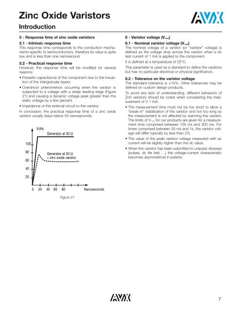
• Overshoot phenomenon occurring when the varistor is<br />
subjected to a voltage with a steep leading edge (Figure<br />
21) and causing a dynamic voltage peak greater than the<br />
static voltage by a few percent.<br />
• Impedance of the external circuit to the varistor.<br />
In conclusion, the practical response time of a zinc oxide<br />
varistor usually stays below 50 nanoseconds.<br />
100<br />
80<br />
60<br />
Volts<br />
Generator at 50 Ω<br />
Generator at 50 Ω<br />
+ zinc oxide varistor<br />
6 - Varistor voltage (V 1mA )<br />
6.1 - Nominal varistor voltage (V 1mA )<br />
The nominal voltage of a varistor (or “varistor” voltage) is<br />
defined as the voltage drop across the varistor when a dc<br />
test current of 1 mA is applied to the component.<br />
It is defined at a temperature of 25°C.<br />
This parameter is used as a standard to define the varistors<br />
but has no particular electrical or physical significance.<br />
6.2 - Tolerance on the varistor voltage<br />
The standard tolerance is ±10%. Other tolerances may be<br />
defined on custom design products.<br />
To avoid any lack of understanding, different behaviors of<br />
Zn0 varistors should be noted when considering the measurement<br />
of V 1 mA.<br />
• The measurement time must not be too short to allow a<br />
“break-in” stabilization of the varistor and not too long so<br />
the measurement is not affected by warming the varistor.<br />
The limits of V 1mA for our products are given for a measurement<br />
time comprised between 100 ms and 300 ms. For<br />
times comprised between 30 ms and 1s, the varistor voltage<br />
will differ typically by less than 2%.<br />
• The value of the peak varistor voltage measured with ac<br />
current will be slightly higher than the dc value.<br />
• When the varistor has been submitted to unipolar stresses<br />
(pulses, dc life test, ...) the voltage-current characteristic<br />
becomes asymmetrical in polarity.<br />
40<br />
20<br />
0 20 40 60 80<br />
Nanoseconds<br />
Figure 21<br />
7