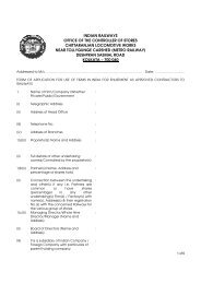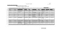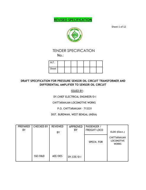
REVISED SPECIFICATION TENDER SPECIFICATION No.:
REVISED SPECIFICATION TENDER SPECIFICATION No.:
REVISED SPECIFICATION TENDER SPECIFICATION No.:

You also want an ePaper? Increase the reach of your titles
YUMPU automatically turns print PDFs into web optimized ePapers that Google loves.
<strong>REVISED</strong> <strong>SPECIFICATION</strong><br />
Sheet-1 of 12<br />
ALT.<br />
<strong>TENDER</strong> <strong>SPECIFICATION</strong><br />
<strong>No</strong>.:<br />
Sheet<br />
DRAFT <strong>SPECIFICATION</strong> FOR PRESSURE SENSOR OIL CIRCUIT TRANSFORMER AND<br />
DIIFFERENTIAL AMPLIFIER TO SENSOR OIL CIRCUIT<br />
ISSUED BY:<br />
DY.CHIEF ELECTRICAL ENGINEER/D-I<br />
CHITTARANJAN LOCOMOTIVE WORKS<br />
P.O. CHITTARANJAN – 713331<br />
DIST. BURDWAN, WEST BENGAL (INDIA)<br />
PREPARED<br />
BY<br />
CHECKED BY<br />
REVIEWED<br />
BY<br />
APPROVED<br />
BY<br />
PASSENGER /<br />
FREIGHT LOCO<br />
ELDO (Elect.)<br />
SPECN. FOR<br />
CHITTARANJAN<br />
LOCOMOTIVE<br />
WORKS<br />
SSE/D&D<br />
AEE/DES<br />
DY.CEE/D-I
Table of Contents<br />
1 Scope<br />
2 Service Conditions<br />
3 Conforming Standards<br />
4 Scope of supply<br />
5 Technical description<br />
6 Submission of offers<br />
7 Tests<br />
8 Type Test<br />
9 Routine Test<br />
10 Labeling/ Marking
TECHNICAL <strong>SPECIFICATION</strong> FOR PRESSURE SENSOR 4.0 BAR USED IN 3-PHASE, 25 Hz, AC<br />
LOCOMOTIVES.<br />
1. SCOPE<br />
This specification covers the supply of Pressure Sensor Oil Circuit Transformer and<br />
Differential Amplifier to Sensor Oil Circuit used in WAG-9 & WAP-5, 6000 HP, 3-Phase, 25 Hz, AC<br />
Locomotives.<br />
In addition to the general conditions of the supply and the requirement given in the<br />
relevant drawing sheet.<br />
2. SERVICE CONDITIONS<br />
Maximum Atmospheric<br />
: + 70 C (in Sun) & +50 C(in shade)<br />
Temperature<br />
Ambient<br />
: -20 … +70 C<br />
Temperature(Operating)<br />
Ambient Temperature<br />
: -30 … +80 C<br />
(Storage)<br />
<strong>No</strong>rmal Humidity : 60%<br />
Maximum Humidity : 100% saturation during rainy season<br />
Altitude : 160 m.a.s.l<br />
Rain Fall : Very heavy in certain areas. The equipment<br />
Should be designed in such a way as to<br />
Withstand its running at 10 Km/hr. In flood water<br />
Level of 102 mm above rail level.<br />
Atmosphere during hot<br />
weather<br />
: Extremely dusty and desert terrain in certain<br />
Areas.<br />
Coastal Areas : Locomotive and equipment will be designed to<br />
Work even in coastal area in humid and salty<br />
Laden atmosphere.<br />
Vibration : The equipment sub-system and their mounting<br />
Arrangement will be designed to withstand<br />
Vibration and shock encountered in the service as<br />
Specified in correspondence unless otherwise<br />
Prescribed.
3. CONFORMING STANDARDS:<br />
The pressure Sensor and Differential Amplifier shall conform to the requirements as per<br />
IEC-721-3-5 or its latest updates/equivalents.<br />
4. SCOPE OF SUPPLY<br />
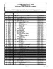
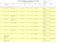
SL <strong>No</strong>. DESCRIPTION CLW DRG. NO.<br />
1 Pressure Sensor Oil Circuit CLW/ES/3/SK-1/0035<br />
Transformer<br />
2 Differential Amplifier to Sensor Oil<br />
Circuit.<br />
CLW/ES/3/SK-2/0035<br />
5. TECHNICAL DESCRIPTION<br />
A. PRESSURE SENSOR<br />
I. DESCRIPTION<br />
Pressure sensor will be of thin film strain gauge technology or Piezo-Resistive<br />
technology.<br />
II.<br />
REUIREMENTS<br />
Ambient temperature range: unit operating: -25°C to +85 °C<br />
Storage temperature range: unit not operating: -25°C to +85 °C<br />
Fluid / Media Temperature range: : -25°C to + 125 °C<br />
Accuracy : < 1.5%FS-Global Error(Including<br />
Linearity,hysteresis &<br />
repeatability<br />
Protection Class : at least IP 53<br />
Output signal : 4 … 20mA<br />
Test voltage : 500V AC 60 sec<br />
Mounting thread : G1/4”<br />
Depth of thread : 11mm<br />
EMC-immunity : as per EN 61000-6-2<br />
Firm may submit relevant test certificates in compliance of above parameters from well<br />
recognized test laboratories. Such laboratories should have proper accreditations from<br />
accredited bodies in India, Europe,USA and UK like NABL,ECCAB or AALA.Competent authority in<br />
CLW may verify such accreditations.
III.<br />
ENVIRONMENTAL CONDITIONS<br />
Fluid : Shell diala S3 ZX-I of M/s Shell/ Power<br />
iv. CABLE<br />
oil TO-10X of M/s Apar as per IEC 60296<br />
Cable Type<br />
: Cable Radox GKW RW/EMV (electron beam Irradiated) from approved<br />
sources of CLW or with prior approval of CLW.<br />
Construction:<br />
Cores 0.5. Mm²<br />
Conductor: stranded tin plated copper<br />
Insulation: Radox GKW/RW<br />
Pin 1 :+UB<br />
2 :GND<br />
The cable screen must be fixed to the sensor housing.<br />
Minimum bending radius: fixed<br />
Free<br />
: 18 mm<br />
: 28 mm<br />
Cable Length: 2.5 Mtrs
V. LOAD RESISTOR<br />
The sensor is a two-wire transmitter.<br />
+ Ub<br />
GND<br />
RL<br />
The maximum allowed load resistor must be calculated using the following<br />
Formula: RL () (UL (V) – 14) X 50. (RL = 100 for UL= 24)<br />
Vi INSTALLATION<br />
Position : The sensor are fixed to the pipe nipple facing downwards.<br />
Possible installation position of the Pressure Sensor<br />
Pipe opening : A 2 mm hole.<br />
Seal : Oil : A copper washer to be used as seal<br />
Water- glycol:<br />
EPDM O-ring<br />
Fixing torque : 8Nm
vii) CONNECTOR: All connection must be of ITT CANNON KPSE06E14-5S or<br />
equivalent model of GIMOTA/AAL..<br />
viii) COPPER WASHER: The copper sealing washer belongs to the delivery.<br />
1.5<br />
13.3<br />
17.9<br />
xi)<br />
Cable Screen must be connected to Connector body & sensor housing to ground of both<br />
ends.<br />
B. DIFFERENTIAL AMPLIFIER:<br />
Pressure range of sensors<br />
0…4bar (relative)<br />
Differential pressure range<br />
0…2bar (polarized)<br />
Operating voltage and U<br />
18…30VDC<br />
Output signal IP<br />
4…20mA<br />
Max. load resistor 2500<br />
Characteristic deviation<br />
0.25%FS<br />
Zero signal<br />
± 0.5%FS<br />
TK zero signal<br />
6. SUBMISSION OF OFFERS<br />
6.1 In case of offers from other than the original equipment manufacturer (OEM),<br />
documentary evidence shall be submitted to prove that he is authorized to offer the<br />
item on behalf of OEM. The suppliers are also liable to produce the original invoice from<br />
OEM if warranted later.<br />
7. TESTS (As per IEC-571)<br />
Nature of test Type test Routine test<br />
Vibration and shock test<br />
√<br />
Performance test<br />
√<br />
Dielectric voltage withstand test √ √<br />
8. TYPE TEST:<br />
VIBRATION AND SHOCK TEST:<br />
The test sample along with its mounting arrangement shall be subjected to the vibration<br />
and shock tests as given below.<br />
8.1 The supplier shall make available one loco set of material as prototype for inspection<br />
and tests at his works and advise the Dy.Chief Electrical Engineer, Chittaranjan as and<br />
when such sample is ready.<br />
8.2 The prototype testing facilities must be arranged by the supplier at his own cost. Tests<br />
shall be carried out as per relevant IEC standard mentioned above. The renderer shall<br />
clearly indicate in the offer, his preparedness for carrying out the prototype tests and<br />
adequacy of facilities to carry out the type /routine test at his premises / on any govt.<br />
approved lab.<br />
8.3 VIBRATION:<br />
The equipment shall be mounted in machine room of electric locomotive and should be capable<br />
to withstand vibration for traction duty as per IEC 61373<br />
The sample with mounting arrangement should be subjected to sinusoidal vibration, the<br />
frequency of which is to be varied progressively between 1 Hz and 100 Hz and amplitude (in<br />
mm) as per:<br />
A=25/f for f between 1Hz and 10 Hz<br />
A=250/f² for f between 10Hz and 100 Hz<br />
The duration will be 10 min. Possibility of resonance is to be detected in this duration.
If resonance is found then the sample should be subjected to sustained vibration, at the<br />
resonance or critical frequency for duration of 15 minutes along each of the three orthogonal<br />
axes. (DIN-EN60068-2-6/ IEC 60068-2-27/ IEC 60068-2-32 or equivalent)<br />
However, if resonance is not found then the sustained vibration should be performed at 10 Hz<br />
frequency.<br />
In both cases the amplitude should be as per the above formula.<br />
8.4 SHOCK:<br />
For 18 mili seconds on each of its axis; the sensor is subjected to 50Hz vibration of such nature<br />
that max. acceleration is equal to 295 m/s² (30g)<br />
The results of the above two tests is satisfactory if there is no resulting damage or abnormality<br />
in operation.<br />
After the test, the sample is should be subjected to performance test (routine) and dielectric<br />
test.<br />
PERFORMANCE TEST:<br />
The pressure sensor output signal of 4-20mA should be checked for calibration (max. 1.5% of full<br />
scale) by imparting 0-4bar pressure at its port. <strong>No</strong>te down the zero offset (Obar pressure 4mA<br />
output signal) and the accuracy at full-scale reading (4bar pressure 20mA output signal).<br />
DIELECTRIC VOLTAGE WITHSTANDS TEST:<br />
The test voltage at normal frequency of 50 Hz and should be as nearly as possible sinusoidal.<br />
All the cable leads of the sensor are shorted and a voltage of 500VAC is applied between that<br />
shorted cable ends and the body of the sensor for 60 seconds. There should not be any flash<br />
over or breakdown.<br />
9.0 ROUTINE TEST<br />
The offered material shall be as per approval model by CLW.The following test shall be carried<br />
out on 10% of samples. In case of failure, entire lot shall be re-offered.<br />
i) Performance II) Di-electric Test<br />
10. LABELLING / MARKING:<br />
Products should be marked with the following:<br />
i) Type NOs. of each product should be punched for identification.<br />
ii) Month and Year of manufacture.<br />
iii) Name of manufacture with trademark, Code <strong>No</strong>. & Batch <strong>No</strong>.
Scope of Supply-<br />
i) Sensor<br />
ii) Cable length-2.5m<br />
iii) Copper Washer<br />
iv) Connector (ITT CANNON)-Plug,<br />
5 Crimp sockets to be provided at the cable end.
Scope of Supply-<br />
i) Sensor<br />
ii) Cable length-2.5m<br />
iii) Copper Washer<br />
iv) Connector (ITT CANNON)-Plug,<br />
5 Crimp sockets to be provided at the cable end.
Pin Configuration<br />
Plug ITT CANON KPSE06E14-5S<br />
Output Signal 4-20 mA<br />
A (Wire 1) Supply +<br />
B (Wire 2) Supply -/Common<br />
C (Wire 3) Connected to enclosure<br />
D<br />
E<br />
<strong>No</strong> terminal mounted<br />
<strong>No</strong> terminal mounted<br />
Screen in cable is essential