
You also want an ePaper? Increase the reach of your titles
YUMPU automatically turns print PDFs into web optimized ePapers that Google loves.
To Promote the production and application of ductile iron castings <strong>Issue</strong> 2, <strong>2007</strong><br />
FEATURES<br />
Finding the True Eutectic Point-<br />
• An Essential Task for Efficient<br />
Process Control of <strong>Ductile</strong> <strong>Iron</strong><br />
AFS Announces Casting of the<br />
•<br />
Year Winners<br />
AFS Announces Casting Design<br />
•<br />
Assistance Program<br />
ATAS Practical Usage at<br />
•<br />
Torrance Casting, Inc.<br />
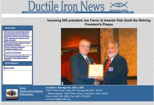
DIS president Joe Farrar (l) Awards Pete Guidi the Retiring<br />
President's Plaque<br />
• <strong>Ductile</strong> <strong>Iron</strong> Welding<br />
FEF Helping Students Become<br />
• Leaders in the Metal Casting<br />
Industry<br />
DEPARTMENTS<br />
• News Briefs<br />
• Advertisers<br />
• Back <strong>Issue</strong>s<br />
Incoming<br />
• DIS Home Page<br />
View<br />
<strong>Ductile</strong> <strong>Iron</strong> Related<br />
Publications<br />
Located in Strongsville, Ohio, USA<br />
15400 Pearl Road, Suite 234; Strongsville,Ohio 44136<br />
Billing Address: 2802 Fisher Road, Columbus, Ohio 43204<br />
Phone (440) 665-3686; Fax (440) 878-0070<br />
email:jwood@ductile.org
2008 Keith Millis Symposium on <strong>Ductile</strong> Cast <strong>Iron</strong><br />
Finding the True Eutectic Point – An essential task<br />
for efficient process control of <strong>Ductile</strong> <strong>Iron</strong><br />
R. Sillén<br />
NovaCast Foundry Solutions AB, Sweden<br />
ABSTRACT<br />
are present.<br />
convenient<br />
For this reason, a simplified and<br />
The position of the eutectic point is traditionally<br />
considered to correspond to a carbon equivalent of 4.3%<br />
for normal cast iron alloys. The paper describes that the<br />
eutectic point is not just a function of the chemical<br />
composition but it is also a function of the nucleation<br />
level for graphite as well as the cooling rate. The<br />
eutectic point can therefore vary considerably e.g. from<br />
4.1 to 4.6% although the chemical composition is<br />
identical. This can lead to errors in controlling the<br />
metallurgical process especially for ductile iron. The<br />
author suggests a new definition of the eutectic point<br />
based on thermal analysis.<br />
Carbon Equivalent (CE) formula is defined and<br />
commonly used in the industry. The method estimates a<br />
number, equivalent to the effect of carbon for each of<br />
these elements. Temperature as a function of CE is<br />
traditionally represented by a binary phase diagram as<br />
shown in Figure 1.<br />
INTRODUCTION<br />
The traditional iron-carbon binary phase diagram shows<br />
the eutectic point at 4.3% carbon for a melt solidifying<br />
with precipitation of austenite and carbon as graphite but<br />
without primary austenite or primary graphite. The binary<br />
Fe-C eutectic temperature is 1148°C (2098°F). The<br />
diagram, although only intended for the binary Fe-C<br />
alloy, is often used for industrial alloys such as cast iron<br />
that also contain silicon, phosphorus, manganese,<br />
sulphur, chromium, nickel, molybdenum etc. Of these<br />
elements, silicon and phosphorus have a significant<br />
effect on the liquidus temperature. For example, silicon<br />
and phosphorus push the eutectic point to the left, i.e.<br />
they reduce the carbon content of the eutectic point. The<br />
effect of silicon on the liquidus temperature has been<br />
found to be equivalent to about 25% of the effect of<br />
carbon. The effect of phosphorus is about 50%. This<br />
means that an increase in 1% silicon is equivalent to an<br />
increase in 0.25% C and that an increase of 0.06% P is<br />
equivalent to an increase of 0.03% C. Knowing the exact<br />
position of the eutectic point is important both for grey<br />
and ductile iron in order to control the solidification and,<br />
hence, for avoiding casting defects.<br />
CONCEPT OF CARBON EQUIVALENT (CE)<br />
Plain cast iron is an alloy of carbon and silicon. The<br />
phase diagram for such a ternary Fe-C-Si alloy is<br />
complex. Phase diagram representation becomes even<br />
more complex when phosphorous and other elements<br />
Figure 1 : Binary phase diagram<br />
Numerous studies have been made on the relationship<br />
between CE and the liquidus temperature. The<br />
relationship is found to be almost linear. The most<br />
correct formula for CE is CE= C+Si/4+P/2. Thus, an iron<br />
with 3.65% C, 2.4% Si and 0.1% P (CE=4.3), would be<br />
considered to solidify fully eutectic i.e. without any<br />
precipitation of neither primary austenite nor primary<br />
graphite.<br />
PROBLEM WITH SIMPLIFIED DEFINITION OF CE<br />
AND THE EUTECTIC POINT<br />
The described, traditional, concept is widely accepted<br />
but seems to be too simplified. It has been shown that<br />
CE calculated from chemical analysis does not always<br />
agree with the one obtained from liquidus relationship.<br />
This is because of the influence of other elements on<br />
liquidus. Using CE calculated from the chemical<br />
composition and assuming that the eutectic point is at<br />
4.3% as basis for grey and ductile iron process control<br />
can be misleading and can lead to costly mistakes.<br />
Copyright © 2008 American Foundry <strong>Society</strong>/<strong>Ductile</strong> <strong>Iron</strong> <strong>Society</strong><br />
100
2008 Keith Millis Symposium on <strong>Ductile</strong> Cast <strong>Iron</strong><br />
One must be aware of the fact that the iron-carbon<br />
diagram is a diagram constructed at equilibrium<br />
conditions and without any other alloying elements. In<br />
reality, many elements influence the liquidus<br />
temperature, e.g. C, Si, P but also several other<br />
elements such as Al, Mg, Mn, Ni, O that are not even<br />
included in the traditional CE-formula. The liquidus<br />
temperature integrates the effect of all of these elements<br />
in the alloy. Therefore, determining CE based on the<br />
liquidus temperature is more accurate and true than<br />
estimating CE from the chemical compositions. The<br />
author suggests naming the carbon equivalent<br />
calculated from the liquidus temperature as the “Active<br />
Carbon Equivalent Liquidus” (ACEL). The liquidus<br />
temperature should be determined using test cups<br />
without tellurium to achieve the highest accuracy.<br />
The eutectic temperature can vary considerably even if<br />
the chemical composition is constant. The reason is that<br />
it depends not only on the chemical composition but also<br />
to a large degree on nucleation of graphite and cooling<br />
rate. It is well know that the eutectic temperature can<br />
increase up to 10°C or more if the iron is inoculated. A<br />
high cooling rate decreases the eutectic temperature<br />
and as it comes closer to the white eutectic temperature,<br />
the risk for chill increases. In the phase diagram, the<br />
eutectic point is where the liquidus line meets the<br />
horizontal eutectic line. The liquidus line is mainly<br />
dependent on the chemical composition, but the<br />
horizontal level of the eutectic line can vary so the<br />
conclusion must be:<br />
composition is not always when CE=4.3 %. The True<br />
Eutectic Point is in fact a dynamic value that depends on<br />
the chemical composition, the cooling rate and the<br />
nucleation level. The new definition can be simplified as<br />
in Figure 2, which shows the liquidus and the eutectic<br />
lines and the eutectic point where the lines meet.<br />
Figure 2 : New definition of true eutectic point.<br />
A typical cooling curve for a ductile iron is shown in<br />
Figure 3. Note that both TL and TElow are 1145°C! It is,<br />
thus, clear that the iron has solidified fully eutectic.<br />
Neither the eutectic composition nor the eutectic<br />
temperature (stable solidification) are fixed at constant<br />
values determined by the chemical composition.<br />
A NEW DEFINITION AND METHOD FOR FINDING<br />
THE TRUE EUTECTIC POINT<br />
One way of measuring solidification and tracing the<br />
actual eutectic composition and temperature is thermal<br />
analysis. With sophisticated electronics and refined<br />
software it is possible to record and analyse cooling<br />
curves very accurately. The ATAS instrument,<br />
developed by NovaCast has been used in this study.<br />
The best method to evaluate if an alloy solidifies eutectic<br />
is to use cooling curve analysis with “grey” curves i.e.<br />
using test-cups without any addition of tellurium. The<br />
method and definition suggested by the author is as<br />
follows:<br />
The True Eutectic Temperature (TEP) is the temperature<br />
where the liquidus temperature coincides with the grey<br />
eutectic temperature (TElow). Thus, the eutectic<br />
Figure 3: Typical ductile iron cooling curve<br />
For hypo-eutectic compositions, the liquidus temperature<br />
can be used to estimate the active carbon equivalent<br />
(ACEL) using the formula ACEL=14.45 – 0.0089*TL.<br />
The low eutectic temperature (TElow) is influenced by<br />
many elements such as Si, Al, P, Mo, Cr and Cu but also<br />
to a large extent by the nucleation status of the melt and<br />
as well as the cooling rate. The nucleation and thereby<br />
TElow can easily be influenced (increased) by<br />
Copyright © 2008 American Foundry <strong>Society</strong>/<strong>Ductile</strong> <strong>Iron</strong> <strong>Society</strong><br />
101
2008 Keith Millis Symposium on <strong>Ductile</strong> Cast <strong>Iron</strong><br />
inoculation. In a hypo-eutectic alloy e.g. a base iron for<br />
ductile iron, an increase in TElow reduces the distance<br />
to TL and the effect is that the alloy will solidify with less<br />
primary austenite or perhaps in a eutectic way if TElow<br />
equals TL.<br />
If we accept the suggested definition that the eutectic<br />
point is reached when TL=TElow, then we must accept<br />
that the eutectic point can vary not only as a function of<br />
TL but also as a function of TElow! The old definition of<br />
the eutectic point as when the chemical composition<br />
equals a carbon equivalent of 4.3% seems wrong!<br />
Our experiences with cooling curve analysis of base and<br />
final ductile iron (which often have a eutectic<br />
composition) have shown that TL can be equal to TElow<br />
at different temperature levels. This is illustrated in<br />
Figure 4 and Figure 5.<br />
Figure 4: Principle of true eutectic points<br />
ACEL=14.45 – 0.089* TL. In this case, TElow is also<br />
1152, which shows the alloy has solidified fully eutectic!<br />
The True Eutectic Point is calculated using the formula<br />
TEP=14.45 – 0.0089*TElow. For case 1 TEP= 4.2% i.e.<br />
the same as the ACEL value.<br />
In case 2 both the liquidus and the low eutectic<br />
temperatures are 1140°C which indicates eutectic<br />
solidification and that the True Eutectic Point in that case<br />
is 4.3%. In case 3 the True Eutectic Point is 4.35% and<br />
the alloy should solidify hypereutectic using the old<br />
definition of the eutectic point. However as the True<br />
Eutectic Point is 4.35% and ACEL is also 4.35% the<br />
alloy solidifies eutectic and without any primary graphite!<br />
The liquidus temperature (TL) is mainly influenced by<br />
the active carbon equivalent (ACEL). The low eutectic<br />
temperature can vary considerably with basically the<br />
same chemical composition if the nucleation or the<br />
cooling rate is varied. If the eutectic point is defined as<br />
when TL=TElow, then the eutectic point can vary as a<br />
function of chemical composition, nucleation and cooling<br />
rate.<br />
If the cooling rate is high, then TElow is reduced due to<br />
undercooling. The alloy in case 2 has a eutectic point at<br />
4.30 % at equilibrium conditions. If the cooling rate is<br />
high (thin walled casting), then TElow is reduced from<br />
1140 to say 1130°C. The alloy will then solidify as a<br />
hypoeutectic alloy with precipitation of primary austenite<br />
which can cause a shrinkage problem. If the foundry<br />
metallurgist had been aware of the new definition of the<br />
eutectic point, he/she could increase TElow by<br />
improving inoculation or raising TElow by increasing<br />
silicon. For thin wall castings, it is well known that the<br />
target in ACEL can be hypereutectic (chemically!) but in<br />
spite of that, the alloy does not solidify with primary<br />
graphite due to a high cooling rate. The high cooling rate<br />
lowers TElow which has the effect that TEP increases.<br />
Note that the true eutectic point (TEP) can only be found<br />
if the iron is allowed to solidify without primary carbides.<br />
This means that the cooling curve analysis must be<br />
made using test-cups without any tellurium. If a tellurium<br />
cup is used, then the iron will solidify “white” and only<br />
show the white eutectic temperature which is very low<br />
(often around 1115 – 1125) and not influenced by<br />
graphite nucleation.<br />
Figures 6 and 7 show examples of cooling curves with<br />
eutectic solidification where the true eutectic point (TEP)<br />
is 4.36% in one of the samples and 4.22 % in the other.<br />
Figure 5: Examples of cases<br />
In case 1, the liquidus temperature is 1152 and ACEL<br />
can be calculated to 4.2% using the formula<br />
Copyright © 2008 American Foundry <strong>Society</strong>/<strong>Ductile</strong> <strong>Iron</strong> <strong>Society</strong><br />
102
2008 Keith Millis Symposium on <strong>Ductile</strong> Cast <strong>Iron</strong><br />
Controlling the grey eutectic temperature within narrow<br />
limits is the key to keeping TElow and thus TEP at a<br />
constant level. By using the described concept, it is<br />
possible to reach the optimal ACEL target in relation to<br />
the true eutectic point (TEP) with high precision. The<br />
result is an iron that is more consistent and less prone to<br />
e.g. shrinkages, which will make it possible to increase<br />
casting yield. A preliminary correlation between the true<br />
eutectic points measured as ACEL as a function of the<br />
liquidus temperature when TL equals TElow is shown in<br />
Figure 8.<br />
Figure 6: TEP is 4.36%<br />
Figure 8: Preliminary correlation<br />
Figure 7: TEP is 4.22%<br />
PRACTICAL IMPLICATIONS<br />
It is good practice to pour ductile iron castings with<br />
alloys that are close to the eutectic point. The traditional<br />
process control method is to calculate the CE-value<br />
based on spectrometer data and to correct it so that<br />
4.3% is reached. This method can lead to considerable<br />
variations, especially in casting properties as the CEvalue<br />
calculated from chemical composition has a<br />
limited accuracy of about +/- 0.05% and because the<br />
true eutectic point is influenced by nucleation and the<br />
cooling rate. Estimating ACEL from a cooling curve<br />
improves the accuracy to about +/- 0.01%, thus, about 5<br />
times more accurate than from a value calculated using<br />
spectrometer data.<br />
In order to obtain a truly eutectic solidification on a<br />
repetitive basis, it is very important not only to keep the<br />
liquidus temperature but also the grey eutectic<br />
temperature at constant levels. As the eutectic<br />
temperature is influenced by nucleation of graphite, a<br />
good quality inoculant must be used and the amount<br />
should be dynamically adjusted based on thermal<br />
analysis measurements. The effect of inoculation is<br />
normally that TElow increases. If the alloy is<br />
hypoeutectic, it means that the distance between TL and<br />
TElow is reduced. Thereby the alloy comes closer to the<br />
eutectic point even though the chemical composition is<br />
almost the same!<br />
The position of the “true eutectic point” is also important<br />
for grey iron. The amount of primary austenite is<br />
important both for physical and casting properties. It is a<br />
function of the active carbon equivalent (ACEL) and the<br />
true eutectic point (TEP). In order to obtain a constant<br />
amount of primary austenite, it is, therefore, important<br />
not only to keep ACEL at a constant level but also to<br />
maintain the eutectic temperature at a constant level.<br />
Additionally, for grey iron, it is very important to keep not<br />
only the liquidus temperature but also the grey eutectic<br />
temperature on a constant level using the dynamic<br />
inoculation method in ATAS.<br />
Copyright © 2008 American Foundry <strong>Society</strong>/<strong>Ductile</strong> <strong>Iron</strong> <strong>Society</strong><br />
103
2008 Keith Millis Symposium on <strong>Ductile</strong> Cast <strong>Iron</strong><br />
REFERENCES<br />
1. NovaCast Foundry Solutions AB – internal research<br />
www.novacast.se<br />
CORRESPONDING AUTHOR<br />
Rudolf Sillén: Rudolf.Sillen@novacast.se<br />
Copyright © 2008 American Foundry <strong>Society</strong>/<strong>Ductile</strong> <strong>Iron</strong> <strong>Society</strong><br />
104
To Promote the production and application of ductile iron castings <strong>Issue</strong> 2, <strong>2007</strong><br />
FEATURES<br />
Finding the True Eutectic Point-<br />
• An Essential Task for Efficient<br />
Process Control of <strong>Ductile</strong> <strong>Iron</strong><br />
AFS Announces Casting of the<br />
•<br />
Year Winners<br />
AFS Announces Casting Design<br />
•<br />
Assistance Program<br />
ATAS Practical Usage at<br />
•<br />
Torrance Casting, Inc.<br />
• <strong>Ductile</strong> <strong>Iron</strong> Welding<br />
FEF Helping Students Become<br />
• Leaders in the Metal Casting<br />
Industry<br />
DEPARTMENTS<br />
• News Briefs<br />
• Advertisers<br />
• Back <strong>Issue</strong>s<br />
AFS<br />
• DIS Home Page<br />
Announces Casting of the Year Winners<br />
IMPORTANT NOTE: High-resolution digital photos of each casting are available by contacting<br />
Christopher Lawson, American Foundry <strong>Society</strong>, at clawson@afsinc.org or 847-824-0181.<br />
Schaumburg, Ill. The metalcasting industry recognized nine cast components as top designs for the <strong>2007</strong><br />
Engineered Casting Solutions and American Foundry <strong>Society</strong> Casting Competition. These components are<br />
being used in a variety of industries, including agriculture, recreation, automotive, military, marine and<br />
heating.<br />
Smith Foundry Co., Minneapolis, earned top honors in the annual competition for its Rangeland Planter<br />
Boot Casting. The component distributes seeds during re-vegetation of arid sites.<br />
Smith’s component was made from austempered ductile iron, weighs 20 lbs., measures 3 x 8 x 19 in. and<br />
was cast via horizontally-parted green sand molding. Originally a steel weldment, the casting achieved a<br />
15% weight reduction, cut lead time by 50% and reduced cost by 65%.<br />
AFS also awarded four Best-in-Class honors and four Honorable Mentions. Following is a look at each of<br />
the award-winning components.<br />
<strong>2007</strong> Best In Class<br />
Snowmobile Chassis Suspension Support, Grenville Castings Ltd., Perth, Ontario. This aluminum,<br />
low-pressure permanent mold casting offers superior strength while limiting overall weight, which improves<br />
performance and decreases gas consumption.<br />
BMW X5 Instrument Panel Cross Car Beam, Lunt Manufacturing Co. Inc., Schaumburg, Ill. This<br />
magnesium diecast component provides 50% weight savings over a comparable steel design without<br />
sacrificing impact strength. It also provided significant cost savings, as it is cast in a two-cavity, highpressure<br />
diecasting mold.<br />
Transmission Main Housing, Denison Industries Inc., Denison, Texas. This A355 aluminum semipermanent<br />
mold component saved an estimated 75% in cost and 50% in lead time over the proposed 15-<br />
20 piece machined and assembled component.<br />
Drop Tube, Signicast Corp., Hartford, Wis. This carbon steel investment casting provided a<br />
dimensionally accurate and consistent part with no secondary operations and allowed the use of selftaping<br />
hardware, reducing the overall cost. Cast threads allowed for an easy assembly of additional<br />
sensors required for this product.<br />
<strong>2007</strong> Honorable Mention<br />
Manifold Housing, Watry Industries Inc., Sheboygan, Wis. This A356 aluminum permanent mold<br />
casting reduced the need for any external plumbing to avoid fluid leaks.<br />
Offset Bracket, Citation Columbiana, Columbiana, Ala. This ductile iron lost foam casting was<br />
converted from a multi-piece fabrication. The 39 cast-in holes reduced the weight of the casting by 20%<br />
without sacrificing strength.<br />
Processing Unit Enclosure, Precise Cast Prototypes & Engineering Inc., Commerce City, Colo. The<br />
A356 aluminum rubber plaster mold casting was cast and delivered within two weeks of the order.<br />
Evolution Size II Bottom Header, Burnham Foundry LLC, Zanesville, Ohio. By including many valueadded<br />
services, the customer realized both time and cost savings over the original weldment design,<br />
which involved processing by several suppliers.<br />
This year’s Casting Competition was sponsored by MAGMA Foundry Technologies, Schaumburg, Ill.<br />
MAGMA will provide Smith Foundry Co. with a one-year license of MAGMASOFT software, including<br />
training and implementation assistance.<br />
For more information on the competition, contact Christopher Lawson at clawson@afsinc.org or 847/824-
0181 x286.<br />
View<br />
<strong>Ductile</strong> <strong>Iron</strong> Related<br />
Publications<br />
Headquartered in Schaumburg, Illinois, AFS is a not-for-profit technical and management society that has<br />
existed since 1896 to provide and promote knowledge and services that strengthen the metalcasting<br />
industry for the ultimate benefit of its customers and society.<br />
Located in Strongsville, Ohio, USA<br />
15400 Pearl Road, Suite 234; Strongsville,Ohio 44136<br />
Billing Address: 2802 Fisher Road, Columbus, Ohio 43204<br />
Phone (440) 665-3686; Fax (440) 878-0070<br />
email:jwood@ductile.org
To Promote the production and application of ductile iron castings <strong>Issue</strong> 2, <strong>2007</strong><br />
FEATURES<br />
Finding the True Eutectic Point-<br />
• An Essential Task for Efficient<br />
Process Control of <strong>Ductile</strong> <strong>Iron</strong><br />
AFS Announces Casting of the<br />
•<br />
Year Winners<br />
AFS Announces Casting Design<br />
•<br />
Assistance Program<br />
ATAS Practical Usage at<br />
•<br />
Torrance Casting, Inc.<br />
• <strong>Ductile</strong> <strong>Iron</strong> Welding<br />
FEF Helping Students Become<br />
• Leaders in the Metal Casting<br />
Industry<br />
DEPARTMENTS<br />
• News Briefs<br />
• Advertisers<br />
• Back <strong>Issue</strong>s<br />
AFS<br />
• DIS Home Page<br />
View<br />
<strong>Ductile</strong> <strong>Iron</strong> Related<br />
Publications<br />
Announces Casting Design Assistance Program<br />
Schaumburg, Ill. The American Foundry <strong>Society</strong> (AFS), in partnership with Product Development &<br />
Analysis LLC (PDA), Naperville, Ill., is pleased to announce our new casting design consultation service<br />
available to both AFS corporate members and casting buyers.<br />
In response to the increasing dependence of casting buyers and design engineers upon casting suppliers<br />
for both casting manufacturing and design expertise, AFS is working with PDA, a firm specializing in<br />
component design, to offer independent casting design, engineering and sourcing solutions. “This project<br />
is an important part of AFS’ efforts to market the metalcasting industry to design engineers and potential<br />
casting customers,” said Jerry Call, AFS executive vice president. “By offering casting design consultation<br />
services through the expertise of PDA, we will ultimately help the U.S. metalcasting industry flourish.”<br />
For more information, contact Alfred Spada, AFS, at aspada@afsinc.org or 847/824-0181.<br />
Headquartered in Schaumburg, Ill., AFS is a not-for-profit technical and management society that has<br />
existed since 1896 to provide and promote knowledge and services that strengthen the metalcasting<br />
industry for the ultimate benefit of its customers and society.<br />
Located in Strongsville, Ohio, USA<br />
15400 Pearl Road, Suite 234; Strongsville,Ohio 44136<br />
Billing Address: 2802 Fisher Road, Columbus, Ohio 43204<br />
Phone (440) 665-3686; Fax (440) 878-0070<br />
email:jwood@ductile.org
To Promote the production and application of ductile iron castings <strong>Issue</strong> 2, <strong>2007</strong><br />
FEATURES<br />
Finding the True Eutectic Point-<br />
• An Essential Task for Efficient<br />
Process Control of <strong>Ductile</strong> <strong>Iron</strong><br />
•<br />
AFS Announces Casting of the<br />
Year Winners<br />
•<br />
AFS Announces Casting Design<br />
Assistance Program<br />
•<br />
ATAS Practical Usage at<br />
Torrance Casting, Inc.<br />
• <strong>Ductile</strong> <strong>Iron</strong> Welding<br />
FEF Helping Students Become<br />
• Leaders in the Metal Casting<br />
Industry<br />
DEPARTMENTS<br />
• News Briefs<br />
• Advertisers<br />
• Back <strong>Issue</strong>s<br />
ATAS<br />
• DIS Home Page<br />
Practical Usage at Torrance Casting, Inc.<br />
John Torrance<br />
Torrance Casting, Inc.<br />
La Crosse, WI<br />
ABSTRACT<br />
The purpose of this paper is twofold; reporting results found by using standard ATAS® (Adaptive<br />
Thermal Analysis System) procedures at Torrance Casting, Inc., and reporting how Torrance uses ATAS<br />
on an advanced level. This paper was written based on my personal experience using ATAS and is<br />
meant to be a narrative on my findings and implemented procedures.<br />
Torrance compared to other ATAS foundry users is relatively small in its melting capacity, roughly 40<br />
tons per day, but has experienced big savings through using ATAS in the first year alone. We have<br />
saved over $60,000 through optimizing our inoculant and FeSiMg additions, and have reduced our<br />
overall metallurgical scrap.<br />
Besides using ATAS for initial cost savings, I believe it is most valuable when it’s used at the furnace.<br />
Recorded ACEL (Active Carbon Equivalent = C% + ¼ Si% + ½ P%) and silicon values, along with<br />
knowing the bath’s equilibrium temperature versus the bath’s holding temperature is my key drivers for<br />
quality control.<br />
INTRODUCTION<br />
ATAS, created by NovaCast Technologies in Ronneby, Sweden, is an advanced thermal analysis system that has established itself as a valuable<br />
tool used in the ferrous metal casting industry. Technical papers within the past few years have cited examples on ATAS optimizing each foundries<br />
melting, treating, and pouring process. ATAS’s method is making relevant parameter data available for analysis, verifying and correcting each<br />
process using pattern recognition learning for quality assurance, and testing and selecting optimal alloying materials and inoculants. As a result<br />
foundries have experienced and reported an overall reduction in metallurgical scrap, improvement on casting yield, less variations in mechanical<br />
properties, and a cost-effective benefit by reducing the amounts of Mg-alloys and inoculants used.<br />
I was first introduced to ATAS by Rudy Sillén (founder of NovaCast) while pursuing my M.S. degree in Metallurgical Engineering at the University of<br />
Alabama under Dr. Doru Stefanescu. Through Rudy’s mentoring while at Alabama and our continual friendship, my knowledge of solidification and<br />
thermal analysis extended beyond my University experience.<br />
When I returned to Torrance we purchased and installed ATAS. Rudy’s immediate recommendations were to work on lowering our inoculant levels.<br />
At that time Rudy made a blanket statement by saying, “most foundries over inoculate their iron without even knowing it.” During that conversation I<br />
mentioned that prior to my return we were having issues with shrink on some of our ductile jobs. The Company was advised to keep their current<br />
post inoculant addition rate of 0.7% FeSi75 and also add a proprietary in-mold tab of roughly 0.35% FeSi75. The new process resulted in more<br />
shrinkage scrap which put the Company in even a worse situation. Once I told this to Rudy, he again reaffirmed me to use ATAS for inoculant<br />
optimization for all our alloys poured.<br />
Before using ATAS I read, and highly recommend reading, “The Use of Thermal Analysis for Process Control of <strong>Ductile</strong> <strong>Iron</strong>”, by Adrian Udroiu who<br />
presented this paper at the NovaCast 2002 Seminar. The paper represents a great overview on ATAS and reviews topics such as;<br />
1. ATAS thermal analysis and parameters<br />
2. How to select optimal chemical composition<br />
3. Pre-Conditioning high steel charge with silicon carbide<br />
4. Selection of optimal FeSiMg-alloy<br />
5. Selecting optimal pouring (holding) temperature<br />
6. Selection of optimal inoculant (foundry specific)<br />
TESTING AND OPTIMIZATION<br />
Using the paper’s techniques we were able to reduce our gray iron inoculant from 0.7% foundry grade FeSi75 to 0.22% proprietary FeSi75<br />
inoculant with an overall cost savings of $36,315 during the first year. Also, by changing to a proprietary inoculant our chilling tendencies were<br />
reduced.<br />
As for our ductile iron procedure the previous method was to add 1.6% FeSiMg using steel chips as cover material. Through ATAS optimization the<br />
addition rate dropped to 1.16% FeSiMg, a cost savings of $12,500 during the first year, with 0.4% foundry grade FeSi75 as a cover. Using 0.4%<br />
FeSi75 as cover material was a recommendation from Rudy and Metallurgical Engineer Dr. Torbjorn Skaland. Taken from an email discussion with
Dr. Skaland he wrote, “In my opinion, the Mg treatment itself is the most important preconditioning of ductile iron, and I like to say that the basis for<br />
a subsequent effective inoculation is made during the Mg treatment. In fact, I believe that very often the Mg treatment is a more important part of<br />
inoculation (nucleation) than the post-inoculant addition itself. Just imagine the huge difference in nucleation behavior between a pure Mg metal<br />
converter process on the one extreme and an in-mold Mg treatment on the other extreme. The pure Mg treatment will be completely white iron if<br />
left un-inoculated. The in-mold iron cannot be inoculated and cannot produce carbides even if you try to (I have tried high carbide promoting<br />
elements and copper chills without success in forming carbides!) Hence, my belief is that you can best get around issues with micro-shrinkage by<br />
designing the MgFeSi alloy and the inoculant alloy correctly. Other alloying is secondary to this issue. The key design criteria for MgFeSi are Mg<br />
and Ca contents, as well as rare earth type and content.”<br />
The optimized ductile process improved the thermal properties of the iron (shown through ATAS results), allowed the furnace holding temperature to<br />
be reduced by 50 °F (which reduces overall nucleation fading), and also improved the cleanliness of the ladle iron by eliminating the rusty cover<br />
steel. The tundish pocket design was even modified for better ATAS results, as shown in Figure 1. We changed the half moon dam design with a<br />
circular pocket design as shown in the figure. The new cylindrical pocket is designed to contain the calculated FeSiMg and FeSi75 cover material,<br />
and also suppress the magnesium reaction thereby improving the magnesium yield and reducing dross formation.<br />
Figure 1 Tundish ladle pocket modification.<br />
The improved tundish iron quality along with ATAS utilization allowed us to drop our current 0.7%<br />
ductile iron inoculant down to a proprietary FeSi75 inoculant addition rate of 0.18%. This was a<br />
cost savings of $12, 240 during the first year.<br />
TORRANCE TESTING PROCEDURES<br />
Torrance ATAS ductile testing includes pouring gray cups (non-tellurium) at the furnace, when<br />
the tundish is half full, and then after the final inoculant has been added. At Torrance, keeping in<br />
mind every foundry is different, our best ductile iron (poured into a 0.65 cm modulus Electro-nite<br />
cup, see Figure 2) is when our final ACEL is between 4.28-4.31, which is on the low end of the<br />
eutectic. We are a jobbing foundry where we pour castings between 1 thru 500 pounds.<br />
Targeting a eutectic iron and monitoring our scrap percentage coming from shrink, I believe<br />
Electro-nite’s 0.65 modulus cup represents our average casting modulus well. That is, ATAS’s<br />
shrink predicting pattern recognition results correlates well with the soundness of our castings<br />
when sampled with a standard Electro-nite cup.<br />
Figure 2 Standard Electro-nite 0.65 cm modulus cup.<br />
However, what if ATAS is used at an automotive foundry<br />
that pours thin-walled castings (high cooling rates) that<br />
require a high ACEL value (hypereutectic)? Or what if<br />
ATAS is used at a wind turbine foundry that pours<br />
extremely heavy sectioned castings (very slow cooling<br />
rates) that require a low ACEL target (hypoeutectic) to<br />
avoid carbon flotation and shrink? Would this 0.65 cm<br />
modulus cup represent those scenarios well? To date I<br />
believe only two different size Electro-nite pouring cups<br />
have been tested with ATAS, the standard 0.65 cm, cup,<br />
see Figure 2 and the smaller 12 mm cup.<br />
I made an in-house trial where I wanted to see what would<br />
happen if I poured two cups side by side with the same<br />
iron where the second cup’s modulus was much higher. To modify the second cup I wrapped a ceramic fiber blanket around the sides and covered<br />
the cup once the cup was poured as shown in Figure 3. The modulus of this modified cup was not calculated.<br />
Figure 3 Top view looking down on Electro-nite’s 0.65 cm modulus cup wrapped in ceramic fiber blanket. After pouring, the cup is<br />
covered by the blanket.<br />
Two trials were poured with base gray furnace iron. The top curves in Figure 4 represent the first trial and the<br />
bottom curves represent the second trial. For both trials the curves on the left were poured into the regular 0.65<br />
cm modulus cup while the curves on the right were poured into the modified cups. The pouring temperatures<br />
between the regular and modified cups were roughly the same. The modified cups took much longer to solidify<br />
because of the slower cooling rate. As expected, different ACEL and Active Carbon, “C”, values (active carbon =<br />
dissolved carbon that has crystallized as graphite. Due to the evolved latent heat it will influence the cooling<br />
curve from TeLow to TS) were recorded between the regular and modified cups. It is my belief that seeing ATAS<br />
was designed off the 0.65cm modulus cup, these results confirm that ATAS recalibration is needed when<br />
changing over to a different size cup (change in modulus).<br />
It was also interesting to see that the regular cups (higher cooling rate) had a higher liquidus temperature (TL) than the modified cups (slower<br />
cooling rate). This was not to be expected seeing a higher cooling rate would promote undercooling, due to lack of nucleation sites, which would<br />
lower the liquidus temperature (TL).
Figure 4 Regular (0.65 cm modulus) cups (left side) vs. modified (insulated) cups (right side).<br />
INITIAL ATAS FURNACE USAGE<br />
After ATAS installation my initial goal was to work on optimizing our inoculant additions.<br />
As mentioned above, this immediately saved the Company money while also improving<br />
the overall metallurgical quality of our iron. However, I believe the most valuable place<br />
for ATAS is at the furnace. My goal was to replace our existing tellurium cup (white cup)<br />
thermal analysis system with the ATAS non-tellurium (grey cup) system. The reasons<br />
for replacing the tellurium system with the ATAS non-tellurium system are;<br />
1. Inaccurate filling (possibly diluting tellurium effect thereby altering results)<br />
a. If the furnace operator fills the cup to the brim initially, the tellurium melting reaction<br />
may bubble some of the iron outside of the cup. Now the furnace operator is left with<br />
two choices. They may either leave the cup alone and hope the iron doesn’t solidify<br />
below the required filling level (5mm below the top of the cup for accurate results,<br />
supposedly), or they may top off the cup with more iron thereby filling the cup to the<br />
brim as needed but potentially altering the results by diluting the tellurium effect.<br />
2. Carbon equivalent (CE) results vary when pouring two cups side by side using a<br />
tellurium system. (Tighter ACEL target ranges have been maintained using ATAS)<br />
3. The tellurium system only records “total carbon” (active plus inactive carbon) where<br />
ATAS grey cups supposedly predict “active carbon”. (To be discussed in depth later)<br />
After running the ATAS system side by side with our tellurium system for more than 6 months without having any issues I decided to drop out the<br />
tellurium system. The initial observations were;<br />
1. Furnace operators loved it because their quiescent filling was consistent.<br />
2. Consistent curves (ACEL’s) when pouring two cups side by side as a result of not using tellurium.<br />
3. ACEL’s displayed roughly the same time the tellurium system displayed CE’s. This is to be expected seeing they are both a function of the<br />
liquidus temperature.<br />
4. One initial drawback when using ATAS alone was the curve takes longer to complete (over 3 minutes compared to around 90 secs. using a<br />
tellurium curve). The reason is the tellurium acts as a chill and alters the carbon solidification by not allowing the carbon to precipitate as<br />
graphite, which eliminates recalescence and shortens the cooling curve.<br />
I needed to find a way around having to wait this extra amount of time (possibly reducing our pouring capacity) for ATAS’s curve to complete and<br />
report the predicted “active carbon”. My solution was remembering how I implemented a Dr. Stefanescu test question in our research foundry at<br />
Alabama. The test question involves using the Ellingham diagram to explain how a “system” always wants to strive towards its lowest free energy as<br />
illustrated in Figure 5. Based on this principle if one knows the carbon/silicon ratio of their furnace bath, the equilibrium temperature can be<br />
calculated and compared to the bath’s temperature which will then assist in predicting whether a bath of iron is losing carbon or silicon over time.<br />
Therefore if the bath temperature is below the equilibrium temperature silicon slag (oxides) will form on top of the melt surface and silicon units will<br />
be lost as an example. On the other hand if the bath temperature is above the equilibrium temperature, carbon monoxide (CO) gas will form and<br />
carbon units will be lost. It is my understanding that this is not a linear relationship but behaves exponentially. So, if you are superheating your bath<br />
you will lose more carbon than if you were just holding the bath above the equilibrium temperature. Nevertheless, this knowledge allowed me to<br />
educate the furnace operators and explain to them the thermodynamic basics behind their daily work.<br />
Figure 5 Metallurgical test question explaining Gibbs free energy,<br />
and the associated equilibrium temperature.<br />
I created a Microsoft Excel mass balance spreadsheet for the furnace operators that act as their “guide” for calculating trim additions and figuring<br />
out the equilibrium temperature for each furnace, as shown in Figure 6. Currently ATAS has a system built into the program that also assists the<br />
user for making trim additions, but there are two issues I had when trying to use this feature. The first problem was based on ACEL and carbon
esults. The program only advised on using either carbon or FeSi75 for making the trim additions, not both. I designed my Excel program to<br />
recommend adding both materials at once if needed, as shown under Furnace 1 in Figure 6. The second problem was that I had to wait over three<br />
minutes for the curve to complete before I could view the “active carbon” and also review ATAS’s recommendations. As I mentioned before, this<br />
could potentially slow production down.<br />
Figure 6 Excel cheat sheet used by our furnace operators.<br />
ACTIVE CARBON<br />
As a review and reminder;<br />
By knowing the bath’s equilibrium temperature, I changed our sampling procedure so that on a new<br />
furnace, the furnace operators would pour an ATAS grey cup and allow the curve to go to<br />
completion. Allowing the curve to go to completion is done solely to obtain the “active carbon”<br />
reading. The ACEL reading is still viewed at the liquidus temperature, roughly 30 seconds into the<br />
curve. The furnace operators would then input the recorded ACEL and carbon reading into the<br />
Excel mass balance program and make any recommended trim additions. Once the furnace<br />
operators know the ACEL and “active carbon” (C) reading, and the fact that we hold our pouring<br />
temperature above the equilibrium temperature, all they need to do for the remainder of the<br />
furnace is to pour a cup and obtain the ACEL (which takes 30 seconds not 3 minutes to view). Any<br />
variation between the newly poured ACEL and the previously poured ACEL is relative to the<br />
furnace carbon activity, which is based on the furnace temperature versus equilibrium temperature,<br />
in theory. Example, if the furnace temperature is above the calculated equilibrium temperature and<br />
the ACEL dropped by three points, only carbon would be used to trim the furnace.<br />
Total Carbon =Active Carbon + Inactive Carbon. Carbon analyzed with a spectrometer or Leco shows ALL carbon in a sample. However it does not<br />
tell us in which form the carbon is present. It can be as carbon dissolved in the ferrite, as iron carbide, as other carbides, as graphite precipitated<br />
from carbon dissolved in the liquid during solidification, and as graphite particles that were not dissolved but suspended in the liquid. For the<br />
metallurgist the interesting part is of course to know how much carbon there is that can result in graphite precipitation, known as “active carbon”.<br />
Active Carbon =dissolved carbon that has crystallized as graphite. Due to evolved latent heat it will influence the cooling curve from TeLow to TS;<br />
therefore it is measured by calculating the area under the curve from TeLow to TS. See figure Figure 7<br />
Inactive Carbon =what is tied up as primary carbides, and /or micro particles of graphite that has not been dissolved.<br />
Figure 7 Example of cooling curve which shows area between TeLow and TS.<br />
During ATAS installation NovaCast recommends using the carbon correction function (see Figure 8)<br />
to offset the carbon differences found between ATAS and Leco carbon combustion, or to use a<br />
tellurium thermal analysis system that predicts total carbon. The problem I see is how can we be<br />
confident that the “active carbon” from ATAS equals the “total carbon” measured by other means?<br />
To look into this further we have to mention what factors can alter “active carbon” metallurgically.<br />
Figure 8 ATAS screen showing carbon correction function.<br />
“Active carbon” can be influenced metallurgically by the amount of oxygen in the melt. The oxygen level in<br />
the bath is erratic and hard to control. High oxygen content reduces the ACEL (higher liquidus temperature)<br />
which makes the iron solidify as is the carbon content were lower than revealed by chemical analysis (“total<br />
carbon”). Factors that increase the oxygen content in iron include high amounts of steel scrap (worse if<br />
rusty), open furnace lid while melting and pouring (oxidizing atmosphere), and holding above the equilibrium<br />
temperature for a long time. Factors that decrease the oxygen content in the iron are addition of deoxidants<br />
such as FeSi, SiC, aluminum, or magnesium. Theoretically a small amount of deoxidant could be added to<br />
the pouring cup or spoon in order to drive out as much oxygen in the iron as possible when trying to<br />
compare ATAS “active carbon” results with Leco “total carbon” results (assuming there is no graphite in the<br />
Leco iron sample).<br />
Another variable that can alter the amount of “active carbon” precipitation is the solidification rate of the iron<br />
poured as shown in Figure 9. This figure is the top portion of Figure 4 where the curve on the right had an<br />
insulated ceramic fiber blanket (see Figure 3) wrapped around the cup which slowed the solidification rate.<br />
Here you can see the “active carbon” on the right is higher because more time was allowed for graphite<br />
precipitation. Another way of altering the solidification is through different pouring temperatures. It is highly recommended to pour the cups at the<br />
same temperature all the time. The red arrows in Figure 9 point to the top of the curve that represents 2462 °F. Pouring temperatures above this<br />
may break the quartz tubes and result in failed curves.<br />
Figure 9 Top portion of Figure 4. Curve on left represents normal cooling curve, while curve on right was from a cup that was insulated to<br />
alter the cooling rate.
Care must be taken to make sure the cooling curves are correct before<br />
fully trusting the carbon reading. A “broken” curve, illustrated in Figure 10,<br />
is when the quartz tube fractures and alters the “active carbon” reading<br />
because the area between TeLow and TS is falsely smaller. So far I have<br />
come across two scenarios where the quartz tube has failed. The first<br />
situation shown on the bottom of Figure 10 is when there is so much<br />
graphite precipitation at once, reflected by a high recalescence value; the<br />
quartz tube cannot withstand the pressure from the precipitation of<br />
graphite and fractures usually around TeHigh. The second situation shown<br />
on the upper portion of Figure 10 is when there has already been<br />
pressure exerted on the quartz tube and there was a mechanical vibration such as dropping charge materials on the floor accidentally which then<br />
fractures the tube.<br />
Figure 10 Example of "broken curves" that alter carbon readout.<br />
MODIFIED AND CURRENT ATAS FURNACE USAGE<br />
For over two years we ran ATAS on its own for gray and ductile iron production. Again the<br />
process was to pour a cup at the beginning of a furnace and allow the curve to go to<br />
completion (roughly 3 minutes). The ACEL and “active carbon” reading would then be inputted<br />
into the Excel spreadsheet program for adjustments. Assuming a constant phosphorous level,<br />
which we can achieve, the program would also back calculate and display the silicon value.<br />
Future sampling for that furnace would only require attaining the ACEL results (roughly 30<br />
seconds). Because we know our bath holding/pouring temperature is higher than the bath’s<br />
equilibrium temperature we know we are constantly losing carbon, therefore any decrease in<br />
ACEL is a result in loss of carbon.<br />
Periodically I would burn a furnace Leco wafer and compare the recorded silicon versus the back calculated ATAS silicon value to make sure the<br />
correct carbon/silicon ratio was kept in line. On one occasion I noticed the ratio was way off, over 30 points! After that occurrence it was my belief<br />
that ATAS was inaccurately calculating “active carbon”. Therefore I ran some experiments where I would purposely add a bunch of carbon to the<br />
melt or allow the carbon to fade away to alter the carbon points. Besides tracking the “active carbon”, ACEL results were also recorded as shown in<br />
Figure 11.<br />
Samples were taken throughout four different heats. Notice on heat #2 at the beginning of the furnace the recorded ATAS Verifier (non tellurium<br />
cup) ACEL was 3.97 while at the end of the furnace it was 3.91. Carbon was being lost throughout the furnace but ATAS Verifier was reporting a<br />
carbon drop of only two points. Remember from thermodynamics at this point carbon should be fading due to being above the equilibrium<br />
temperature. I purposely added FeSi75 at the end of this furnace to try and “save” the ACEL. ATAS White (tellurium cup), DataCast (tellurium cup),<br />
and Leco all showed that the “total carbon” was down and the silicon was up as expected. As we know “active carbon” cannot be greater than<br />
“total carbon” as it was shown here.<br />
Heat #3 was a furnace where I intentionally added FeSi75 throughout emptying. Notice how ACEL started at 3.93 and ended up at 3.94, a one<br />
point change while constantly adding FeSi75. “Active carbon” actually went up a couple of points while the ATAS Verifier calculated silicon value,<br />
from using the Excel spreadsheet, stayed roughly the same. However the tellurium cups and Leco results showed that silicon increased, as<br />
expected, and the carbon dropped.<br />
Heat #4 I intentionally added a lot of carbon to see if the “active carbon” value would increase. The results stayed the same as not to be expected.<br />
We know the carbon got into solution however because the ACEL drastically jumped up accordingly.<br />
Figure 11 ATAS Verifier (non tellurium cup), ATAS White (tellurium cup), DataCast (tellurium cup), and Leco data comparisons.<br />
The goal of using ATAS Verifier (non tellurium) cups at the furnace is for getting stable ACEL<br />
readings, which is by far the most important parameter, and to trust the “active carbon”<br />
(carbon/silicon ratio). As you can see I had an issue with the “active carbon” reporting, which<br />
throws off the carbon/silicon ratio. So, I developed a new thermal analysis testing method that is<br />
still being used today, without having any issues.<br />
The new and current method is to pour an ATAS non tellurium cup at the furnace to record the<br />
ACEL, which is read 30 seconds into the curve. A tellurium cup (ATAS White or DataCast for<br />
example) is also poured at the beginning of every new furnace to record the silicon value,<br />
usually out of the same spoon of iron. If you are in a hurry to get a silicon result, I would<br />
recommend pouring a DataCast sample over an ATAS White sample because the DataCast<br />
curve completes a lot sooner. Besides that, either system would work. Also, I had to modify the<br />
Excel mass balance program so that it would back calculate my carbon value instead of silicon.<br />
Warning: When the type K thermocouple wire is exposed to temperatures over 2480 °F significant variation of the predicted silicon measurement<br />
can occur. To maintain the best accuracy of the carbon and silicon prediction the cup manufacturer recommends pouring the molten iron into the<br />
cup at temperatures less then 2480 °F. Independent test results show that if the temperature is poured below this value, the reported silicon value
may offset the actual target/chemical value plus or minus 4 points, resulting in an eight point spread. When the pouring temperature is above 2480<br />
°F, the reported value may offset the target value plus or minus 8 points, or a 16 point spread.<br />
Instead of pouring a tellurium cup to analyze the silicon content, a spectrometer could also be used. This by far is the most accurate way to<br />
measure silicon, but I decided to not go this route because not only was it a slower method, more manpower would be needed to run the<br />
spectrometer. Besides, if our tellurium cups were poured below 2480 °F our silicon value should be at the most 4 points off target. That is<br />
equivalent to only one ACEL point, and obviously better than being off 30 silicon points! Currently our target ACEL range for gray and ductile iron is<br />
3 points total for each.<br />
So looking at it from a different perspective as long as we have our initial ACEL and silicon values and knowing our holding temperature is above<br />
the equilibrium temperature, a change in ACEL throughout the furnace is a change in the carbon (loss if ACEL drops). Again, the rest of the cups<br />
only need to record ACEL for the operator to use the Excel mass balance spreadsheet. Double checking silicon by pouring an extra tellurium cup is<br />
always an option too.<br />
Conclusion<br />
Even with the trouble we experienced with the “active carbon” readings, I believe ATAS is a valuable thermal analysis system that can be used<br />
online at the furnace. I believe the pros numerously outweigh the cons. We saved more than $60,000 in inoculant and FeSiMg consumption alone<br />
during the first year. Not everyone inoculates as heavily as we did to generate some of the savings, but imagine the savings if your foundry were<br />
bigger than ours. In addition by properly inoculating our iron our metallurgical scrap has also reduced.<br />
has impOnce optimization testing has been carried through, I believe using ATAS at the furnace is where is it is needed most. Reducing process<br />
variation upstream has improved our overall quality control downstream.<br />
View<br />
<strong>Ductile</strong> <strong>Iron</strong> Related<br />
Publications<br />
Located in Strongsville, Ohio, USA<br />
15400 Pearl Road, Suite 234; Strongsville,Ohio 44136<br />
Billing Address: 2802 Fisher Road, Columbus, Ohio 43204<br />
Phone (440) 665-3686; Fax (440) 878-0070<br />
email:jwood@ductile.org
To Promote the production and application of ductile iron castings <strong>Issue</strong> 2, <strong>2007</strong><br />
FEATURES<br />
Finding the True Eutectic Point-<br />
• An Essential Task for Efficient<br />
Process Control of <strong>Ductile</strong> <strong>Iron</strong><br />
•<br />
AFS Announces Casting of the<br />
Year Winners<br />
•<br />
AFS Announces Casting Design<br />
Assistance Program<br />
•<br />
ATAS Practical Usage at<br />
Torrance Casting, Inc.<br />
• <strong>Ductile</strong> <strong>Iron</strong> Welding<br />
FEF Helping Students Become<br />
• Leaders in the Metal Casting<br />
Industry<br />
DEPARTMENTS<br />
• News Briefs<br />
• Advertisers<br />
• Back <strong>Issue</strong>s<br />
DUCTILE<br />
• DIS Home Page<br />
IRON WELDING<br />
Carl R. Loper, Jr.<br />
University of Wisconsin-Madison<br />
University of Wisconsin-Milwaukee<br />
William Knuerr<br />
Oil City <strong>Iron</strong> Works<br />
Corsicana, TX<br />
Introduction<br />
Welding of any member of the family of cast irons is typically considered problematic, particularly when<br />
compared to the welding of structural steels. This reaction applies whether the welding of cast irons is to<br />
be a structural matter (joining components together) or whether welding is used to salvage the casting in<br />
a manner such that it would be suitable for engineering applications. The inherent problems in the<br />
welding of cast irons are metallurgical, and must be addressed based on an understanding of welding<br />
procedures, of cast iron solidification and phase transformations occurring during heating and cooling of<br />
the cast iron. The objective being one of being able to produce a weld and its heat affected zone with<br />
the metallurgy and mechanical properties of the base metal, i.e., the casting involved.<br />
The weldability of a particular material is usually considered to be the production of a fusion weld (either<br />
as bead on plate, or the joining of components together) in a manner such that the weldment does not<br />
contain injurious imperfections (more commonly described as defects when they detrimentally affect<br />
metallurgical structure, properties and subsequent manufacturing operations). A broad classification of<br />
weld defects in a given material subjected to fusion welding would include the following:<br />
1. Defects involving inadequate bonding. These are usually matters such as incomplete penetration of the weld metal into the base metal; lack of<br />
fusion between the weld metal and the base metal, or between portions of weld metal; inadequate joint geometry; etc.<br />
2. Defects from the introduction of foreign inclusions. These may involve the formation of oxide films; the entrapment of slag or metal/gas reaction<br />
products; delamination (due to the presence of undesirable inclusion distribution in the base metal as affected by the fusion welding procedure); etc.<br />
3. Geometric effects. This involves the shape of the weld and/or weldment including: undercutting (fusion of base metal without adequate<br />
compensation with weld metal); excessive reinforcement (excessive deposition of weld metal – both externally and internally; etc.<br />
4. Metallurgical effects. First, undesirable metallurgical structures related to microsegregation, e.g., hot cracking and fissures; cold cracking and<br />
delayed cracking; stress relief cracking; strain age cracking; gas porosity; etc. In addition, problems resulting from metallurgical reactions, e.g.;<br />
embrittlement; structural notches; etc.<br />
No reasonable fusion weld is perfect, and all fusion welds can be expected to contain some of these imperfections. But an acceptable weld must not<br />
contain imperfections that would be detrimental to the use of the welded product.<br />
The root causes of weld defects can be attributed to one or more of several conditions:<br />
1. Lack of welding know-how and experience.<br />
2. Welding process characteristics.<br />
3. Base metal defects or compositions.<br />
4. Materials selection and properties.<br />
5. Welding environment (joint design, fit up, temperature, support, etc.<br />
In consideration of the welding of a member of the family of cast irons, comparisons are often made to the welding of steels, either for structural<br />
purposes or for the upgrading of steel castings. However, steels (even those which have been alloyed for one purpose or another) do not present<br />
the complex metallurgical, or solidification phase control, characteristics that are paramount in cast irons. The fusion welding of steels typically<br />
entails the melting and solidification of single phase structures, not necessarily homogeneous. On the other hand, the unique feature of the family of<br />
cast irons is the formation of two significant phases during solidification (one of which is graphite) and the control of that phase morphology. Fusion<br />
welding of cast irons starts with this intricate phase morphology, involves the melting or transformation of those phases (usually a process which is<br />
not the reverse of their solidification formation), and the re-solidification of this structure.<br />
Furthermore, the composition of the matrix phase (or phases) in cast irons is affected not only by alloying elements in ferrite and austenite, but by<br />
the presence of excess carbon in graphite or carbide phases and the solubility of that carbon in ferrite and austenite.
Phase Changes Occurring During Heating of Cast <strong>Iron</strong>s<br />
It is of interest to summarize the major phase changes that take place during the heating of cast irons in fusion welding. Initially the cast iron<br />
microstructure consists of the excess carbon phases (graphite and carbide), the matrix (ferrite and/or pearlite), and the intercellular structure. No<br />
significant changes typically occur on heating until austenite starts to form (changes in pearlite lamellae are minor). Pearlite and the intercellular<br />
structure will transform to austenite first (compositions near eutectoid), with ferrite transforming later (with carbon diffusion from graphite).<br />
Homogeneity of the austenite depends upon time and temperature, although diffusion rates for carbon are appreciably greater than for alloying<br />
elements (e.g., Si, Mn, Ni, Cr, Mo, etc.).<br />
The ability of the matrix to withstand stresses introduced during the non-uniform heating of cast irons is a function of the matrix microstructure.<br />
Ferritic matrices provide the greatest opportunity for dimensional adjustment (yielding). Finer pearlite lamellae will be more prone to crack initiation,<br />
as will intercellular regions which typically contain carbides.<br />
Melting starts to take place where the local composition has the lowest melting point (near eutectic composition). Since the local carbon content is a<br />
critical factor in this regard, the first areas to melt are observed at the graphite austenite interface and in the intercellular regions (where there is a<br />
lower melting point due to carbon and alloying element concentrations). Carbon is more accessible from the edges of the graphite basal planes so<br />
that melting starts at the tips of flake graphite, at the graphite spheroid-austenite interface, at the temper carbon-austenite interface, etc. The<br />
process of melting develops over a temperature range so that a zone of partial fusion can be expected outside of the resultant fusion zone.<br />
Within the fusion zone convection insures homogeneity of melt composition. However, a thin region at the edge of the fusion zone remains<br />
unmixed. The composition of the fusion zone is, of course a function of the amount of dilution due to different metal compositions or filler metals.<br />
Phase Changes Occurring During Cooling of Cast <strong>Iron</strong>s<br />
On cooling, the most rapid cooling rates are in the fusion zone, with cooling rates decreasing as distance from the fusion zone increases. Cast iron<br />
microstructures are highly sensitive to cooling rate variations, both during solidification and solid state transformation. Sensitivity of the fusion zone<br />
to cooling rates depends upon the composition of the melt in the fusion zone. If it is a typical cast iron composition, solidification will favor carbide<br />
and under cooled graphite formation. If sufficiently alloyed, say with nickel, these undesirable morphologies will be minimized or eliminated.<br />
However, the liquid which formed in the zone of partial fusion remains highly susceptible to solidification as eutectic carbide. If the liquid in the<br />
partial fusion zone is interconnected, a region of brittle eutectic carbide will be present to serve as a path for crack formation. The ability to limit the<br />
interconnection within the partial fusion zone depends upon the initial microstructure of the cast iron and the welding procedures used.<br />
When permitted to cool at a sufficient rate into or through the Ms-Mf temperature range martensite formation will occur. To avoid martensite<br />
formation it is necessary to cool sufficiently slowly through this temperature range (essentially from red to black as the casting cools).<br />
Typical Modifications of Procedures for the Welding of Cast <strong>Iron</strong>s<br />
As noted earlier, the fusion welding of cast irons is usually compared to procedures used in the welding of structural steels, with modifications of<br />
those procedures to accommodate the metallurgical characteristics of cast irons. The more significant of these procedure modifications will be<br />
discussed.<br />
Avoidance of Martensite Formation. The presence of silicon, and of the possible saturation of carbon in austenite by drawing carbon from the<br />
graphite phase, greatly increases the effective hardenability of the austenite matrix – both martensitic and pearlitic hardenability. The propensity for<br />
cracking therefore requires that cooling through the Ms-Mf temperature range be sufficiently slow that martensite formation will not occur. This is<br />
accomplished by pre-heating the casting, or the region of the casting to be welded to a temperature of at least 500F, maintaining that temperature<br />
throughout welding followed by slow cooling to room temperature.<br />
Minimizing the Partial Fusion Zone. Because the eutectic of cast irons solidifies (and melts) over a range of temperatures a zone of partial fusion<br />
outside of the weld fusion zone cannot be prevented from forming. Cooling rates within this region are sufficient for the melt in this region to solidify<br />
as a carbidic eutectic. One must minimize the extent of this partial fusion zone in order to prevent the development of a cracking path just outside<br />
of the fusion zone. This requires that a sufficiently steep thermal gradient be maintained throughout welding, thereby minimizing the thickness of the<br />
partial zone and the interconnection of eutectic melt.<br />
The geometry of this partial fusion zone is also a function of the graphite morphology, since the partial fusion zone develops as a result of eutectic<br />
liquid formed as a diffusion couple between graphite and austenite forming preferentially where the carbon basal planes are exposed, around the<br />
circumference of spheroidal graphite, in certain regions of compacted graphite, a the ends of flake graphite, throughout temper carbon nodules, etc.<br />
Avoiding Carbide Formation in the Fusion Zone. The highest cooling rates in fusion welding are encountered within the fusion zone. If the<br />
composition of the fusion zone is typical of a cast iron the fusion zone will solidify with a predominance of carbidic eutectic. To avoid this one must<br />
either alter the melt composition of the fusion zone or develop a fusion zone melt composition that has sufficient graphitizing potential to avoid<br />
carbide formation. In the first case this is readily accomplished by using a nickel bearing filler metal so that sufficient nickel dilutes the base metal in<br />
the fusion zone preventing eutectic carbides . In the second case a technique must be employed that provides the required graphitizing potential.<br />
One procedure that has been developed for the welding of cast irons, particularly ductile irons, is an oxyacetylene welding procedure that was<br />
patented in 1967 , but which is generally unknown today to casting producers or designers. This fusion welding procedure is being used to produce<br />
metallurgically satisfactory welds over the range of mechanical property requirements of engineering grade ductile iron castings.<br />
Summary of the Welding Procedure<br />
This fusion welding procedure consists of the following steps:
1. Preheating of the casting to a temperature above the Ms temperature of the base metal, and maintaining that temperature until welding has been<br />
completed.<br />
2. Use of an oxy-acetylene flame for welding, a suitable flux and a filler rod of a chemistry that matches that of the base metal.<br />
3. Air cooling of casting to ambient temperature.<br />
4. Post weld stress relief or heat treatment as necessary to obtain desired matrix structure.<br />
Welding is conducted using an oxy-acetylene welding torch to which a powder spray device has been added. This device holds a quantity of<br />
material (flux) which can be aspirated into the oxygen and acetylene gas streams. A torch having a number 36 tip has been found satisfactory. The<br />
flux used is a proprietary blend of metallic compounds, ferrosilicon and magnesium ferrosilicon alloys which has been ground to a fine powder. The<br />
essential constituents of this flux are shown in Table I.<br />
The flux constituents noted in Table I are not present elementally (e.g., Mg, Si, Ca, Ce, etc.) but are present as more convenient alloys of<br />
compounds. For example: Mg may be present as a 5% MgFeSi alloy; Si may be present as FeSi, CaSi or MgFeSi alloy; Ce may be present as a<br />
halide or incorporated into another alloy. The principle fluxing agent is borax.<br />
Table I. Flux Composition<br />
Table II. Exemplar Flux Compositions<br />
% Min. % Max.<br />
Mg 1.50 2.50<br />
Si 30.0 50.0<br />
Ca 10.0 *<br />
Ce 0.25 4.00<br />
Borax 20.0 40.0<br />
*Not critical<br />
Examples of two satisfactory flux formulations are presented in Table II.<br />
% %<br />
Mg 2.50 2.08<br />
Si 41.0 36.0<br />
Ca 10.0 16.0<br />
Ce 0.25 0.80<br />
Al Trace 1.20<br />
Other RE Trace 6.17<br />
Borax 30.0 20.0<br />
Fe Bal. Bal.<br />
These flux compositions are hydroscopic and must be maintained dry requiring storage in a suitable weld rod hot box. In order to assure free<br />
flowing in the welding torch, the particle size of the flux may be as large as 140 mesh, however, the flux is typically ground to a particle size under<br />
200 mesh.<br />
Filler metal is supplied using weld rod cast into rod shape or from machined from ductile iron castings having the same composition as the subject<br />
casting. A machined rod is preferable in order to eliminate any influence of the metal/mold interface (e.g., inclusions, metallurgical surface effects,<br />
etc.). The dimensions of the weld rod are not critical, but should enable ease of handling during welding. This rod is also stored in a weld rod hot<br />
box to prevent surface oxidation.<br />
Fusion Welding of <strong>Ductile</strong> <strong>Iron</strong><br />
As with most fusion welding, but particularly with oxy-acetylene welding the welding procedure is operator sensitive, requiring some skill and<br />
experience and requires training over a period of time producing welds that will be examined metallurgically. The goal of this procedure is not<br />
merely to excavate a portion of the casting and to adequately fill that excavation with weld metal, but to accomplish this task in a manner such that<br />
there is minimal metallurgical difference between the weld metal, the heat affected zone and the base metal. In this way metallurgical integrity (and<br />
assurance of mechanical properties) is achieved.<br />
The first step involves the removal of the unacceptable condition from the casting, or suitable edge preparation of components to be joined. This<br />
requires preparation down to clean, defect free base metal and a minimum 60° angle. The area to be welded (or the entire casting) is uniformly<br />
heated to, and maintained at, 650° F. When using gas torches for pre-heating and maintaining temperature during welding, the flame should be<br />
neutral or slightly reducing (avoiding excessive oxidation of the casting surfaces as well as carbon soot deposition). Where possible, welding should
e conducted in the horizontal, or flat, position. After pre-heating the weld area is further heated using the oxy-acetylene spray torch, the weld rod<br />
is held adjacent to the flame while the heat of the flame is concentrated in the center of the area to be welded. When a molten puddle starts to<br />
form, the weld rod is brought to the tip of the inner torch cone where it is melted, and the molten rod is permitted to drop into the puddle. At that<br />
time, the lever on the spray torch is depressed with a quick snap introducing the flux into the puddle. Each time a drop of molten weld rod drops<br />
flux is added in this manner. This procedure is followed while moving in a circular manner until the region is slightly overfilled. After welding has<br />
been completed, the casting is slowly cooled to about 650° C in order to prevent cracking, and then air cooled to ambient temperature. This is of<br />
particular concern in larger castings.<br />
Post weld heat treatment depends upon the metallurgical and physical property requirements for the specific casting. For ASTM A-536 ductile irons,<br />
the nodule count developed in the weld metal is sufficient to avoid the formation of excessive carbides or intercellular structure. Accordingly a<br />
stress relief heat treatment will relieved the residual stresses developed during cooling after weld repair. When the weld metal and base metal<br />
matrix structures are to be matched, appropriate heat treatment is necessary. In highly alloyed ductile irons, such as ASTM A-439, a full post weld<br />
heat treatment is necessary. That involves heating the casting to 1650° F and holding at temperature for 3 hours, or for one hour per inch of casting<br />
section, furnace cooling to 980° F followed by air cooling to ambient temperature.<br />
This fusion weld repair procedure is applicable to a wide range of castings and casting section thicknesses. Typical thicknesses range from 3/8 to<br />
10 inches.<br />
Assessment of Effective Welds<br />
A weld test coupon was devised for the purpose of illustrating the metallurgical characteristics and mechanical properties of ductile irons welded by<br />
this process. The geometry of this coupon is shown in Figure 1. This 1 inch thick coupon can be produced from any grade of ductile iron and<br />
contains a 3/8 inch deep oblong depression 1.5 in. wide by 3 in. long. The test piece is designed so that 0.5 in. D. tensile bars can be machined<br />
from the two legs, with the welded section in the reduced portion of the bar where a minimum of 60% of the test bar cross section is composed of<br />
weld metal. The weld test coupon may be heat treated in any manner called for to meet customer<br />
specifications. The microstructure of the weld metal, heat affected zone and base metal may be determined from the weld test coupon or from the<br />
machined tensile bars.<br />
Figure 1. Test piece used for the evaluation of welded ductile iron. Depression in cast block filled with weld metal. Test bars (2) machined<br />
so that the weld constitutes a minimum of 60% of the tensile test bar cross section in the reduced region.<br />
ASTM A536 Grade 80-55-06. An example of typical microstructures obtained from welding this ductile iron grade (mildly alloyed to insure a pearlitic<br />
matrix) is shown in Figures 2a (transition zone) and 2b (weld fusion zone). The weld fusion zone exhibits a uniform dispersion of graphite spheroids<br />
with a high nodule count. Many of those spheroids have been enveloped by a shell of ferrite during solid state transformation. No carbides are<br />
present, and the nodule count is sufficiently high so that no significant intercellular structure has developed. The transition zone between the weld<br />
fusion zone and the base metal reveals the increased nodule count developed in the fusion zone. It is apparent that the alloy content of the filler<br />
metal was somewhat higher than that of the casting being welded as indicated by the difference in the ferrite shell thickness in those regions.<br />
There is no indication of the zone of partial fusion in this photomicrograph.<br />
Tensile properties of typical as cast ductile irons in the unwelded and welded condition have been presented in Table III. The tensile properties are<br />
similar and represent acceptable ductile iron structures, although the elongation values indicate somewhat higher pearlite content.<br />
ASTM A536 Grade 60-40-18. An example of typical microstructures in the base metal, weld metal and transition zone obtained in welding a 60-40-<br />
18 grade of ductile iron is presented in Figures 3a and 3b. In this case the welded casting was subjected to sub critical anneal to insure removal of<br />
pearlite form the matrix. This procedure,
however, was only partially successful in that a spherodized carbide structure is present in regions that were formerly pearlite. A full anneal followed<br />
by suitable slow cooling<br />
Figure 2a (upper). Transition between base metal (upper portion of the photomicrograph) and weld metal (lower portion) of ASTM grade<br />
80-55-06 ductile iron.<br />
Figure 2b (lower). Weld fusion zone of welded grade 80-55-06 grade ductile iron.<br />
would have eliminated these spherodized carbides. As with the pearlitic grade, the weld fusion zone exhibits a rather uniform dispersion of graphite<br />
spheroids and a high nodule count. The transition zone exhibits a similar spherodized pearlite structure in the base metal, in which the nodule<br />
count is somewhat lower than that of the pearlitic grade shown in Figure 2. Some residual evidence of the zone of partial fusion is present where a<br />
carbidic structure had developed around spheroidal graphite.<br />
Table III shows typical tensile properties of welded and unwelded ductile irons that have been normalized (after welding). The tensile properties for<br />
the as cast material exceeds the 60-40-18 grade requirements, while the welded material properties represent acceptable ductile iron structures for<br />
a 65-45-12 grade with slightly higher pearlite present.
Figure 3a (upper). Transition zone of welded ASTM A539 grade 60-40-18 ductile iron illustrating the structure of the base metal (top<br />
portion of the photomicrograph) the transition zone and the weld fusion zone (lower portion of the photomicrograph).<br />
Figure 3b (lower). Weld fusion zone of ASTM A539 grade 60-40-18 ductile iron.<br />
ASTM A536 Grade 120-90-02. Tensile properties of welded and unwelded ductile irons produced to this grade of ductile iron are also shown in<br />
Table III. The properties of the unwelded and welded samples are similar and represent acceptable<br />
ductile iron, although one of the welded samples is softer with lower strengths likely due to the high nodule count of the weld metal.<br />
ASTM A439 Modified. Tensile test coupons taken from exemplar welded ASTM A439 Grade D5B modified ductile iron resulted in the data shown<br />
in Table III. It is apparent that the tensile properties of these two test bars did not meet the minimum values required in ASTM A439 Grade D5B,<br />
having been low in elongation and borderline in tensile strength, but quite adequate in yield strength. This is attributed to the aforementioned<br />
carbide network developed, primarily in the zone of partial fusion, due to the introduction of Mo in the modified version of this alloy. The<br />
enhancement of this network in the partial fusion zone resulted in decreased elongation and tensile strength which was not evident in either<br />
separately cast test bars or in test bars machined from casting sections.<br />
Table III. Tensile Properties of Welded ASTM A536 <strong>Ductile</strong> <strong>Iron</strong>2<br />
TS Ksi YS ksi El % HB<br />
As Cast Unwelded 87.6 68.4 8.0 217<br />
As Cast Welded 84.4 67.2 5.0 223<br />
As Cast Welded 86.2 67.8 6.0 223<br />
Annealed Unwelded 65.2 47.8 19.0 156<br />
Annealed Welded 66.4 46.0 16.0 149<br />
Annealed Welded 62.6 48.2 14.5 143<br />
Normalized Unwelded 93.4 76.4 4.0 235<br />
Normalized Welded 97.2 77.0 4.0 241<br />
Normalized Welded 100.2 78.2 3.5 255<br />
Q&T (1000F) Unwelded 121.6 90.8 2.5 302<br />
Q&T (1000F) Welded 117.2 87.2 3.5 269<br />
Q&T (1000F) Welded 120.2 91.4 2.0 293<br />
Table IV. Tensile Properties of Welded ASTM A439 Modified <strong>Ductile</strong> <strong>Iron</strong><br />
Dia. in. Area sq. in.<br />
Tensile Load, Yield Load,<br />
lb.<br />
lb.<br />
T.S. ksi Y.S. ksi El. %<br />
0.500 0.1963 10,600 7,460 54.5 38.0 3.0<br />
0.499 0.1956 10,790 7,250 55.0 37.1 4.0<br />
Summary<br />
The ductile iron welding procedure described is a process applicable to the salvage of ductile iron castings, or to the joining of ductile iron<br />
components, resulting in machinable ductile iron microstructures in the weld metal, zone of partial fusion and base metal. Similar tensile properties<br />
in the weld metal, partial fusion zone and base metal could be expected if the microstructures are adequately controlled. However, it is anticipated<br />
that most applications of these casting repair procedures will be non-structural and will provide machinable material with a color match of the<br />
original casting.<br />
Acknowledgements<br />
The authors wish to thank others at Oil City <strong>Iron</strong> Works, Inc. for their support and assistance in the development and application of ductile iron
welding: Eric Meyers, President; Eric R. Meyers, Vice President; and William Riley, Vice President, Manufacturing.<br />
Figures 4a (upper). Transition zone between the base metal (upper portion of the photomicrograph) and the weld metal (lower portion) of<br />
ASTM A439 modified ductile iron. Figure 4b (lower). Weld fusion zone of ASTM A429 modified ductile iron.<br />
References<br />
1. Welding of Cast <strong>Iron</strong>, American Welding <strong>Society</strong>, Miami, FL, 1985.<br />
2. D. T. Roberts, New <strong>Ductile</strong> <strong>Iron</strong> Welding Process Saves Castings and Dollars, Welding of Cast <strong>Iron</strong>, AWS, 1985, pp 69-71.<br />
View<br />
<strong>Ductile</strong> <strong>Iron</strong> Related<br />
Publications<br />
Located in Strongsville, Ohio, USA<br />
15400 Pearl Road, Suite 234; Strongsville,Ohio 44136<br />
Billing Address: 2802 Fisher Road, Columbus, Ohio 43204<br />
Phone (440) 665-3686; Fax (440) 878-0070<br />
email:jwood@ductile.org
To Promote the production and application of ductile iron castings <strong>Issue</strong> 2, <strong>2007</strong><br />
FEATURES<br />
Finding the True Eutectic Point-<br />
• An Essential Task for Efficient<br />
Process Control of <strong>Ductile</strong> <strong>Iron</strong><br />
AFS Announces Casting of the<br />
•<br />
Year Winners<br />
AFS Announces Casting Design<br />
•<br />
Assistance Program<br />
ATAS Practical Usage at<br />
•<br />
Torrance Casting, Inc.<br />
• <strong>Ductile</strong> <strong>Iron</strong> Welding<br />
FEF Helping Students Become<br />
• Leaders in the Metal Casting<br />
Industry<br />
DEPARTMENTS<br />
• News Briefs<br />
• Advertisers<br />
• Back <strong>Issue</strong>s<br />
News<br />
• DIS Home Page<br />
MEETINGS - BUSINESS - PEOPLE<br />
MEETINGS<br />
Briefs<br />
The Keith Millis Symposium will be held at the Orleans Hotel and<br />
Casino in Las Vegas, Nevada, October 20-23, 2008. The meeting<br />
will feature a full technical program.<br />
BUSINESS<br />
Flake skin formation in CGI castings presented at GIFA by<br />
Ashland<br />
DUBLIN, Ohio – A research paper from Ashland Casting<br />
Solutions, a business group of Ashland Performance Materials, a<br />
division of Ashland Inc. (NYSE:ASH), presented at the GIFA<br />
international foundry trade exposition in Dusseldorf, Germany,<br />
addressed “flake skin” issues that can occur when foundries cast<br />
parts using compacted graphite iron (CGI).<br />
“Our data show that conditions of slow cooling rates and an<br />
imbalance between spheroidizing and oxidizing elements at the<br />
mold metal interface promote formation of flake skin with lamellar<br />
graphite at the casting surface,” said Jörg Kroker, Ph.D., global<br />
technology director, Ashland Casting Solutions. “We need to<br />
continue research in this area because flake skin can decrease the<br />
strength and ductility of a cast CGI part.”<br />
Industry data, reflecting cast iron usage, show that more CGI is<br />
being used to produce diesel engine blocks because of its combined<br />
strength, thermal conductivity and vibration dampening properties.<br />
The paper presented various scenarios testing the potential for CGI<br />
to form flake skin at the metal mold interface, and delivered<br />
suggestions of possible causes for flake skin formation.<br />
Ashland Casting Solutions, a business group of Ashland<br />
Performance Materials, is a leader in supplying products,<br />
processes, services and technologies to the global metal casting<br />
marketplace.<br />
Ashland Performance Materials, a division of Ashland Inc., is a<br />
worldwide manufacturer and supplier of specialty chemicals and<br />
customized services to the building and construction, packaging<br />
and converting, transportation, marine and metal casting industries.<br />
It is a technology leader in metal casting consumables and design<br />
services; unsaturated polyester and vinyl ester resins and gelcoats;<br />
and high-performance adhesives and specialty resins.<br />
Ashland Inc. (NYSE: ASH), a diversified, global chemical<br />
company, provides quality products, services and solutions to<br />
customers in more than 100 countries. A FORTUNE 500 company,<br />
it operates through four divisions: Ashland Performance Materials,
Ashland Distribution, Valvoline and Ashland Water Technologies.<br />
To learn more about Ashland, visit www.ashland.com.<br />
Ashland research shows virtual core optimization in castings<br />
reduces scrap<br />
DUBLIN, Ohio – Improper filling of a metal casting tool with sand<br />
can lead to an increase in scrap potential. A research paper from<br />
Ashland Casting Solutions, a business group of Ashland<br />
Performance Materials, a division of Ashland Inc. (NYSE:ASH),<br />
presented at the GIFA international foundry trade exposition in<br />
Dusseldorf, Germany, supports using a virtual approach to core<br />
production and blow tube and vent locations.<br />
“Filling multiple impression core boxes has been a struggle for<br />
many foundries over the years,” said Nigel Yeomans, project<br />
manager, Ashland Casting Solutions. “By utilizing a virtual<br />
approach to this issue, foundries can better design the sand blowing<br />
profile and optimize their sand magazine design.”<br />
The research presented at GIFA, provided participants insight to<br />
blowing difficulties associated with sand magazines. The research<br />
presented a series of experiments and computational process<br />
simulations to address sand magazine performance. In addition,<br />
discussions of computational analyses to optimize blow tube and<br />
vent locations for core filling, tool wear and density, and curing<br />
analysis were presented.<br />
Ashland Casting Solutions, a business group of Ashland<br />
Performance Materials, is a leader in supplying products,<br />
processes, services and technologies to the global metal casting<br />
marketplace.<br />
Ashland Performance Materials, a division of Ashland Inc., is a<br />
worldwide manufacturer and supplier of specialty chemicals and<br />
customized services to the building and construction, packaging<br />
and converting, transportation, marine and metal casting industries.<br />
It is a technology leader in metal casting consumables and design<br />
services; unsaturated polyester and vinyl ester resins and gelcoats;<br />
and high-performance adhesives and specialty resins.<br />
PEOPLE<br />
Back to top<br />
View<br />
<strong>Ductile</strong> <strong>Iron</strong> Related<br />
Publications<br />
Located in Strongsville, Ohio, USA<br />
15400 Pearl Road, Suite 234; Strongsville,Ohio 44136<br />
Billing Address: 2802 Fisher Road, Columbus, Ohio 43204<br />
Phone (440) 665-3686; Fax (440) 878-0070<br />
email:jwood@ductile.org