62 Robam-Väizene-Anepaio-Kolats-Valgma 2008
62 Robam-Väizene-Anepaio-Kolats-Valgma 2008
62 Robam-Väizene-Anepaio-Kolats-Valgma 2008

You also want an ePaper? Increase the reach of your titles
YUMPU automatically turns print PDFs into web optimized ePapers that Google loves.
5 th International Symposium<br />
„Topical Problems in the Field of Electrical and Power Engineering”,<br />
Doctoral School of Energy and Geotechnology<br />
Kuressaare, Estonia, January 14 – 19, <strong>2008</strong><br />
Measuring mining influence in the form of students practice in<br />
opposition to the emotional environmental impact assessment<br />
Karin <strong>Robam</strong>, Vivika Väizene, Ain <strong>Anepaio</strong>, Margit <strong>Kolats</strong>, Ingo <strong>Valgma</strong><br />
Department of Mining, Tallinn University of Technology<br />
karin.robam@ttu.ee<br />
Abstract<br />
Environmental impact assessment of mining<br />
influence is a procedure that involves an analysis<br />
of vibration, noise and drainage water effects on<br />
the environment and effects that attends if<br />
drainage water has been pumped out of mines.<br />
Data for environmental impact assessment,<br />
geotechnological research and teaching comes<br />
mainly from fieldwork measurements, laboratory<br />
analysis and modelling. Measuring is useless<br />
without laboratory analysing and modelling or<br />
processing of the data with modern software. In<br />
addition to analysing and taking into account the<br />
comments new results and conclusions have to be<br />
produced. The purpose of the analysis is to find out<br />
and appraise the positive or negative impact of<br />
mining influence.<br />
Keywords<br />
Fieldwork, environmental impact of mining,<br />
geotechnology, experiments, testing, modelling,<br />
visualisation.<br />
Introduction<br />
Environmental impact assessment base on available<br />
data, which is gathered from fieldwork or laboratory.<br />
In this article is handled environmental impact<br />
assessment through noise, ground vibration, water<br />
velocity, flow and discharge from the mines.<br />
Data is gathered from measurements in the course of<br />
science club fieldworks. The science club of mining<br />
and geology was started in the spring semester of<br />
2006, where the excursions to the phosphorite<br />
grounds in Maardu and to the limestone deposit in<br />
Harku took place to assess the effects of mining<br />
(http://mi.ttu.ee/teadusklubi) [2].<br />
Students are included in fieldworks to make studies<br />
more attractive and interesting. During the<br />
fieldworks students adjust better to the speciality and<br />
it expands the knowledge about using modern<br />
equipment, which increases the quality of student’s<br />
work.<br />
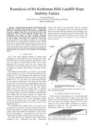
Measuring water velocity, flow and<br />
discharge from the mines<br />
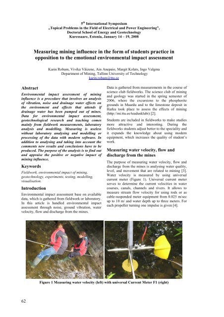
The purpose of measuring water velocity, flow and<br />
discharge from the mines is analysing water quality,<br />
level, and movement that are related to mining [3].<br />
Water velocity is measured by using universal<br />
current meter (Figure 1). Universal current meter<br />
serves to determine the current velocities in water<br />
courses, canals, channels and rivers. It allows to<br />
measure stream flow velocity for using rods or as<br />
cable-suspended meter equipment from 0.025 m/sec<br />
up to 10 m/ and water depth up to three meters. For<br />
each propeller turning one impulse is given [4].<br />
Figure 1 Measuring water velocity (left) with universal Current Meter F1 (right)<br />
<strong>62</strong>
That portion of the channel cross section in which<br />
flow occurs is called active portion and a cross<br />
section where the flow velocity is nonexistent is<br />
called off-channel storage or dead storage. The area<br />
of a channel has to divide into shares according to<br />
profile of channel width. Firstly have to measure the<br />
distance from shore and water depth at various<br />
points across the stream flow to construct a channel<br />
profile. The current velocity meter may be used to<br />
determine a vertical axis of water velocity at several<br />
points across a stream channel.<br />
As a result of surveying distance from the bank,<br />
water depth, current meter depth to water level and<br />
number of propeller rotations are measured and<br />
scheme of the flow is constructed (Figure 2). The<br />
stream flow for the profile is the sum of the average<br />
velocities of each subsection of stream flow times its<br />
cross-sectional area.<br />
0<br />
Streambed width, m<br />
0 0,5 1 1,5 2 2,5 3 3,5 4 4,5<br />
-0,05<br />
Streambed depth, m<br />
-0,1<br />
-0,15<br />
-0,2<br />
-0,25<br />
-0,3<br />
-0,35<br />
Water surface<br />
Universal current meter depth to water level<br />
Streambed<br />
Stream vertical axis<br />
Figure 2 Streambed cross section<br />
Test pumping for evaluating hydraulic<br />
conductivity of the rocks<br />
Submersible pump MP1 (Figure 4) is used for test<br />
pumping. It is specially designed for the purging and<br />
sampling groundwater in boreholes with an internal<br />
diameter of at least 50 mm and the dynamic water<br />
level must not exceed 80 metres. Pumping water out<br />
of boreholes is used to determine the coefficient of<br />
hydraulic conductivity. Pump has to be performed in<br />
several wells where water level will be surveyed. As<br />
the result of pumping water level decreases around<br />
the borehole and depression cone will be developed.<br />
As pumping continues, a cone of depression with its<br />
centre at the pumped well spreads out from well in<br />
all directions. The dimensions of the cone of<br />
depression depend upon the rate of recharge, the<br />
water-bearing properties and extend of the aquifer,<br />
the rate and duration pumping.<br />
If borehole passes through sort of unvaried soil level<br />
the coefficient of hydraulic conductivity (Figure 3)<br />
is calculated with the next formula:<br />
k<br />
2,303Q<br />
1<br />
= log [5]<br />
2 2<br />
π(h 1 + h 2)<br />
r2<br />
r<br />
Figure 3 Determining the coefficient of hydraulic<br />
conductivity<br />
63
Figure 4 Testpumping in the abandoned spoils of a strip mine<br />
Monitoring ground and air vibration<br />
Vibration can cause negative effects to the human<br />
health and to the reliability of mining machines.<br />
That is why it is important to keep vibration level<br />
under limited value and control it by carrying out<br />
measuring with vibration monitors. In order to get<br />
most accurate results device should be attached<br />
directly to the object under study. For measuring<br />
vibrations of soil and rock ground under the<br />
vibration monitor should be cleaned and monitor<br />
itself fixed with bolts (Figure 6).<br />
Log shows the results as 4 channels: 3 geophone<br />
channels, 1 microphone channel [6].<br />
According to the graphic of results of vibration<br />
analysis (Figure 5) it is possible to assess vibration<br />
influence.<br />
Figure 6 Positioning monitor towards vibration<br />
source<br />
Figure 5 Results of vibration analysis near<br />
Surface miner milling cutter<br />
Noise measurement<br />
Noise measurement are performed with device TES<br />
1352A. It is used for measuring machine influence<br />
on the environment also noise influence on sanitary<br />
conditions in populated areas and is necessary for<br />
valuating working conditions on mechanical<br />
processing.<br />
Noise is advised to measure from certain distance<br />
like 1m, 5m, 10m etc. Measuring results are store on<br />
the machine memory what can be drawn into the<br />
computer with program called Sound Meter and<br />
processed in appropriate software (Figure 7).<br />
64
110<br />
105<br />
Sound level (dB, A)<br />
100<br />
95<br />
90<br />
85<br />
Sound intensity<br />
80<br />
9:59:02 10:01:55 10:04:48 10:07:41 10:10:34 10:13:26 10:16:19<br />
Time<br />
Figure 7 Measuring noise of a hydraulic hammer (left), Noise chart of a surface miner milling (right)<br />
Acknowledgements<br />
Field works and this paper is related to the Estonian<br />
Science Foundation study- Grant No. 6558.<br />
References:<br />
Figure 8 Measuring mining benches, angles and<br />
elevations for understanding the technology<br />
Conclusions<br />
Modern testing equipment and software allows to<br />
produce and evaluate environmental impact of<br />
mining.<br />
Due to measuring water velocity, flow and discharge<br />
from the mines, test pumping for evaluating<br />
hydraulic conductivity of the rocks, monitoring<br />
ground and air vibration it is possible to analyse<br />
mining impact to environment.<br />
The most easy and useful way is to perform the<br />
measurement in the form of science club that has<br />
been successfully started in Mining department of<br />
Tallinn University of Technology.<br />
1. Karu, V. Science club of Mining and<br />
Geology. EU legislation as it affects mining. INFRA<br />
22944 TAIEX workshop. 2006.<br />
2. Karu, V; Pärnasalu, R; Õnnis, A. Science<br />
Club of Mining and Geology as it Affects Higher<br />
Education. Doctoral school of energy and<br />
geotechnology. Tallinn University of Technology<br />
2007<br />
3. Reinsalu Enno, Lind Helena, <strong>Valgma</strong> Ingo,<br />
Technogenic water body in closed oil shale mines,<br />
Oil Shale, Estonian Academy Publishers, Tallinn,<br />
2006, -<br />
4. Equpiment for water pumping Eijkelkamp.<br />
http://www.eijkelkamp.com [30.10.2007]<br />
5. Jaaniso, V. Soil Mechanics and<br />
Engineering Geology<br />
http://www.tud.ttu.ee/material/epi/Valdo_Jaaniso/Ge<br />
otehnika%20alused/PinmehA.doc [30.10.2007]<br />
6. Vibration monitor<br />
http://www.abem.se/products/vibraloc/Vibraloc.pdf<br />
[31.10.2007]<br />
65