GV150 / GV151 - Elektro-Trading sp. z oo
GV150 / GV151 - Elektro-Trading sp. z oo
GV150 / GV151 - Elektro-Trading sp. z oo

You also want an ePaper? Increase the reach of your titles
YUMPU automatically turns print PDFs into web optimized ePapers that Google loves.
control – motion – interface<br />
ELEKTRO-TRADING <strong>sp</strong>. z o.o<br />
Tel. +48 (0-32) 734-55-72<br />
Tel/Fax +48 (0-32) 734-55-70<br />
E-Mail et@elektro-trading.com.pl<br />
http://www.elektro-trading.com.pl<br />
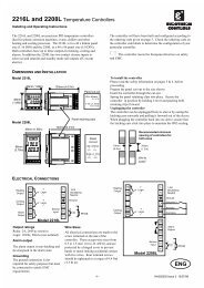
<strong>GV150</strong> / <strong>GV151</strong><br />
Impulse Amplifier and Splitter<br />
for Encoder Signals<br />
• Impulse input (A, /A, B, /B, Z, /Z, TTL level or HTL level)<br />
• Potential separation by high <strong>sp</strong>eed opto-couplers<br />
• 6 output channels, each (A, /A, B, /B, Z, /Z)<br />
<strong>GV150</strong>: all outputs TTL / RS422<br />
<strong>GV151</strong> outputs individually programmable to either TTL or HTL level<br />
• Frequency range 0 - 400 kHz<br />
• Front LED’s for indication of input pulses A, B and Z<br />
• Elimination of noise and cross talking on transmission lines<br />
• Closed aluminum cassette for mounting in 19"racks or assembly on<br />
DIN mounting rails<br />
Operating Instructions<br />
<strong>GV150</strong>02B_e.DOC / Mrz-08 Page 1 / 8
Safety Instructions<br />
• This manual is an essential part of the unit and contains important hints about<br />
function, correct handling and commissioning. Non-observance can result in<br />
damage to the unit or the machine or even in injury to persons using the<br />
equipment!<br />
• The unit must only be installed, connected and activated by a qualified electrician<br />
• It is a must to observe all general and also all country-<strong>sp</strong>ecific and application<strong>sp</strong>ecific<br />
safety standards<br />
• When this unit is used with applications where failure or maloperation could cause<br />
damage to a machine or hazard to the operating staff, it is indi<strong>sp</strong>ensable to meet<br />
effective precautions in order to avoid such consequences<br />
• Regarding installation, wiring, environmental conditions, screening of cables and<br />
earthing, you must follow the general standards of industrial automation industry<br />
• - Errors and omissions excepted –<br />
Version:<br />
<strong>GV150</strong>02B/hk_03/2008<br />
Description:<br />
First motrona edition with A5 brochure format<br />
<strong>GV150</strong>02B_e.DOC / Mrz-08 Page 2 / 8
Table of Contents<br />
1. Application and Construction..........................................................................4<br />
2. Connections, Switch Settings.........................................................................5<br />
3. Block Diagram.................................................................................................6<br />
4. Input Pin Assignment......................................................................................7<br />
5. Output pin assignment....................................................................................7<br />
6. Technical Data ................................................................................................8<br />
<strong>GV150</strong>02B_e.DOC / Mrz-08 Page 3 / 8
1. Application and Construction<br />
The unit is used to increase the drive capability of existing encoder signals and to distribute the<br />
signals to several channels. At the same time it provides potential separation between source<br />
and target lines as well as level conversion.<br />
In general, an incremental encoder output is limited to drive currents of 20 mA only on it's<br />
impulse lines. The <strong>GV150</strong> amplifiers increase the Fan-Out to 6 channels, each loadable with 20<br />
re<strong>sp</strong>ectively. 30 mA per line. The units can be used for encoder pulse transmission and for data<br />
transmission applications as well.<br />
As a standard, <strong>GV150</strong> and <strong>GV151</strong> provide TTL (RS422) inputs (A, /A, B, /B, Z, /Z)<br />
With Option HTLIN1, the input is set to HTL level (12...30V), and only the signals A, B and Z<br />
necessary (no inverted signals).<br />
With option HTLIN2, the input is also set to HTL level ( 12...30V ), but all signals must be<br />
applied (A, /A, B, /B, Z, /Z).<br />
Each of the 6 output channels generates the signals (A, /A, B, /B, Z, /Z) .<br />
<strong>GV150</strong> provides always TTL/ RS422 standard and<br />
<strong>GV151</strong> has individually programmable output levels TTL or HTL<br />
<strong>GV150</strong>02B_e.DOC / Mrz-08 Page 4 / 8
2. Connections, Switch Settings<br />
a. The unit is supplied by a power connector on the front side.<br />
The power supply range is 18 - 30 VDC.<br />
b. For operation without potential separation, positions 3 and 4 of the internal DIL switch<br />
S1 can be set to "ON". This will connect the input GND to the output GND and to the<br />
Minus potential of the power supply<br />
c. Pin 4 of the input connector provides an auxiliary voltage output, when the DIL-switch<br />
positions 1 and 2 are set to "ON".<br />
When DIL-switch positions 1 and 2 are set to "ON", never any external voltage<br />
must be applied to pin 4!<br />
The aux. output voltage is 5,5V/ 300mA with TTL inputs and 24V/ 300mA with options HTLIN1<br />
and HTLIN2.<br />
Input<br />
4<br />
IN<br />
1<br />
2<br />
220 R (TTL)<br />
1K5 (HTL)<br />
S1<br />
Opto<br />
+ 5V (TTL)<br />
+ 24V (HTL)<br />
Output<br />
out<br />
5<br />
3<br />
4<br />
S1<br />
5<br />
Werkseinstellung:<br />
Factory setting:<br />
1OFF, 2OFF<br />
3 ON, 4 ON<br />
GND<br />
-<br />
+<br />
24VDC<br />
GND<br />
All DIL switches become accessible when you remove the right hand side plate.<br />
LED "On”<br />
LED input pulses A<br />
LED input pulses B<br />
LED Input pulses Z<br />
1234<br />
S1<br />
With <strong>GV151</strong> only<br />
12345678 1234<br />
S2 S3<br />
<strong>GV150</strong>02B_e.DOC / Mrz-08 Page 5 / 8
3. Block Diagram<br />
A<br />
A<br />
B<br />
B<br />
Z<br />
Z<br />
+5V<br />
GND<br />
OPTO<br />
<strong>GV150</strong><br />
<strong>GV151</strong><br />
<strong>GV150</strong><br />
<strong>GV150</strong>-1<br />
+5V<br />
+24V<br />
<strong>GV151</strong><br />
(<strong>GV150</strong>-1)<br />
1<br />
2<br />
3<br />
4<br />
5<br />
6<br />
S2<br />
A<br />
A<br />
B<br />
B<br />
Z<br />
Z<br />
GND<br />
A<br />
A<br />
B<br />
B<br />
Z<br />
Z<br />
GND<br />
A<br />
A<br />
B<br />
B<br />
Z<br />
Z<br />
GND<br />
OUT 1<br />
OUT 2<br />
OUT 3<br />
3<br />
4<br />
1<br />
2<br />
S1<br />
7<br />
8<br />
A<br />
A<br />
B<br />
B<br />
Z<br />
Z<br />
GND<br />
OUT 4<br />
1<br />
2<br />
S3<br />
A<br />
A<br />
B<br />
B<br />
Z<br />
Z<br />
GND<br />
OUT 5<br />
Power<br />
+5V<br />
3<br />
4<br />
A<br />
A<br />
B<br />
B<br />
Z<br />
Z<br />
GND<br />
OUT 6<br />
GND<br />
-<br />
+<br />
24 VDC<br />
<strong>GV150</strong>02B_e.DOC / Mrz-08 Page 6 / 8
4. Input Pin Assignment<br />
(Sub-D-9 male on the unit) * See DIL switch S1<br />
B<br />
A<br />
A<br />
*) *)<br />
+5,5V GND<br />
*) *)<br />
B A +24V GND<br />
*) *)<br />
B A A +24V GND<br />
1 2 3 4 5<br />
6 7 8 9<br />
1 2 3 4 5<br />
6 7 8 9<br />
1 2 3 4 5<br />
6 7 8 9<br />
Z Z B<br />
Standard TTL<br />
Z<br />
Option HTLIN1<br />
Z Z B<br />
Option HTLIN2<br />
5. Output pin assignment<br />
(Sub-D-9 female on the unit)<br />
GND<br />
A<br />
A<br />
B<br />
Output 1<br />
Output 2<br />
Output 3<br />
Output 4<br />
Output 5<br />
Output 6<br />
5 4 3 2 1<br />
9 8 7 6<br />
1K<br />
HTL<br />
TTL<br />
HTL<br />
TTL<br />
HTL<br />
TTL<br />
HTL<br />
TTL<br />
HTL<br />
TTL<br />
HTL<br />
TTL<br />
1 2345678 1 234<br />
ON<br />
OFF<br />
B +5V Z Z<br />
S2<br />
(<strong>GV151</strong>)<br />
S3<br />
With <strong>GV151</strong>, you can select the desired output level (TTL/HTL) by setting the associated<br />
position of the DIL switch to „ON“ (with the other position OFF).<br />
Setting both TTL and HTL to ON at a time would result in HTL output.<br />
For safety reasons, the default factory setting is always TTL like shown above.<br />
<strong>GV150</strong>02B_e.DOC / Mrz-08 Page 7 / 8
6. Technical Data<br />
Power Supply<br />
Aux. Voltage on input<br />
Max. Frequency<br />
: 18.....30 VDC (200 mA + encoder current)<br />
: 5 V DC, 300 mA (TTL) / 18...30 V DC, 300 mA (HTL)<br />
: 400 kHz (TTL output) / 250 kHz (HTL output)<br />
Inputs : TTL : (A, /A, B, /B, Z, /Z), (10 mA) Low = 0...1,5V<br />
High = 3...5,5V<br />
Outputs<br />
HTLIN1: ( A, B, Z ) (14 mA / 24 V) Low = 0...4V<br />
High = 11...30V<br />
HTLIN2: (A, /A, B, /B, Z, /Z), (14mA / 24 V) Low = 0...4V<br />
High = 11...30V<br />
: 6 x (A, /A, B, /B, Z, /Z),<br />
<strong>GV150</strong> : TTL/ RS422, 20 mA<br />
<strong>GV151</strong> : TTL / HTL (push-pull), 30 mA<br />
Signal delay Input / Out : <strong>GV150</strong> : 200 nsec<br />
<strong>GV151</strong> : 700 nsec<br />
Dimensions : 14TE x 3HE ( b x h x t = 70 x 129 x 175 mm )<br />
(w x h x d = 2.756’’ x 5.079’’ x 6.890’’)<br />
Weight<br />
Temperature range<br />
: 650 g<br />
: Operation: 0° ... +45°C (+32 … +113°F)<br />
Storage: -25° … +70°C (-13 … +158 °F)<br />
Ordering Information : <strong>GV150</strong>/ GV 151 : TTL input (A, /A, B, /B, Z, /Z),<br />
<strong>GV150</strong>/ GV 151 / HTLIN1 : HTL input A, B, Z<br />
<strong>GV150</strong>/ GV 151 / HTLIN2 : HTL input (A, /A, B, /B, Z, /Z)<br />
Option SM 150 : Backplane prepared for DIN rail<br />
mounting.<br />
Conformity and standards : EMC 89/336/EEC: EN 61000-6-2<br />
EN 61000-6-3<br />
LV73/23/EEC: EN 61010-1<br />
<strong>GV150</strong>02B_e.DOC / Mrz-08 Page 8 / 8